saccani
-
Posts
52 -
Joined
-
Last visited
Content Type
Profiles
Forums
Gallery
Downloads
Blogs
Events
Store
Aircraft
Resources
Tutorials
Articles
Classifieds
Movies
Books
Community Map
Quizzes
Everything posted by saccani
-
Speaking just on what the aircraft can do, 'Runway 16 is on the short side, but you should see how wide it is'. Flaps up stall is 37 knots @ 818 kg (you would likely have less than that for a first flight), flaps down is 30 knots. TOSS with flaps is 36 knots. One wrinkle is that your ASI may very well be reading zero with a high rate of climb when you start off. With these kinds of aircraft, you can point them into the wind described and takeoff in about half the width of 07, get to TOSS almost immediately, then crab along 07. Demonstrated crosswind capability (not limit) in the conventional sense is 25 knots. Landings are a little trickier, as you have to allow for a likely shear in most fields and be careful to kick the rudder to match your ground path, not the runway centreline, then adjust your path to remain on the runway. Although in most cases, you could just full stop into wind across the runway, then taxi as required. Of course, you crab as required to maintain extended centreline and the circuit so that other traffic can easily understand where you are going.
-
I don’t want to dispute your view about design feature endorsement, I would say that it doesn’t necessarily feel that different to me. But all of the STOL CH 700 and 800 series have very different handling to typical aircraft, particularly with flap down. Part of this is from interaction of flaperon and rudder control systems, part from having no fin, part from the slats. It wasn’t for nothing that after flight test CASA required the deletion of flap functions (reverting to ailerons) when certifying the Skyfox. I suspect that adverse yaw from roll inputs is what has put you off flaperons. That isn’t inherently there, it can be removed with careful design, notably with differential aileron, but most small aircraft designers put a higher priority on weight control. In this case, obstruction windshear might have been helpful, reducing the tailwind. I guess one takeaway from this might be to emphasise the importance of the pre-takeoff self brief in formulating a plan of action before it is needed, taking note of the conditions of the day and what force landing options there are. That sets you up for success, instead of having to think about it later. I’m not suggesting the pilot neglected this, I’m simply reminded of the benefits - and that I haven’t been getting as much from them as I can.
-
On the contrary, reporting the name of an incident pilot (regardless of their survival) does do something for aviation safety. It allows relevant information to be found and allows a quick assessment of the likelihood of an incident being of a widely relevant technical nature to be assessed. However, this can also be counter productive to self reporting etc… Knowing the name of the pilot, who had previously removed flaperon washout on another aircraft he built suggested that he might have done so again, which is directly related to the dreadful outcome of this crash - it then enables me to directly advise *you* not to do so, if you were contemplating this. Your emotional outbursts, on the other hand, really do contribute nothing to air safety and might even reduce it by stifling reasoned debate and reasonable speculation. You have attacked all contributors indiscriminately. I think everyone here is both sympathetic and empathetic to the lost pilot - who really is identified in pubic records - because we can see ourselves in the same place. This is very different from disrespecting the dead. I am extremely sorry for what happened to him. I am also mindful of how upsetting it might be to be falsely reported dead.
-
A reliable witness on the aerodrome states that it didn’t get above 200 feet and appeared to lose power. At that distance he could not hear the engine. Crosswind was estimated at 8 knots from the right, but he observed the aircraft making a left turn. Shortly after, it appeared that the aircraft stalled with a left wing drop, before he lost sight of it below the tree line. Impact was near the boundary fence of a turf farm, which may have been an attractive landing spot. The paddock at the end of the runway is a little rough, but the witness felt straight ahead or a right turn into wind offered best odds. The left turn increased ground speed, whilst if the turf farm was the object, the glide may have been stretched, resulting in the calamitous outcome of departing controlled flight and landing in the same paddock with a higher ground speed. Another reliable witness reported that there was no flaperon washout. These aircraft don’t normally drop a wing on stall, even with aileron application. Removal of washout makes a wing drop on stall more likely. This aircraft type has unconventional handling and usually has no break in a power off stall, retaining control but quickly developing a 3 to 6 knot sink rate. The aircraft was fitted with a modified O-360 using non-integrated electronic ignition and fuel injection. A carburettor was retained as an alternate fuel system. I believe attention should be directed to these modifications and also as to whether or not a five minute full power test was conducted to verify satisfactory fuel flow. Shorter tests often fail to reveal inadequate fuel flow rates, particularly if a header tank is used. A
-
Home made is *exactly* what it was, the owner built it and obtained an amateur built experimental airworthiness certificate on that basis.
-

Do we have this requirement here in AUS for RAA aircraft.
saccani replied to SSCBD's topic in AUS/NZ General Discussion
The metal jacket is an extra cost, optional feature. Being Australia, they import what they want to sell, not what we want to buy. The great irritation is that we are forced to pay extra for a “feature” we don’t want and really should be removing for aircraft use. For those employing a LAME on their experimental or LSA, the removal comes at extra cost.... -
RFS air tanker feared crashed in NSW
saccani replied to BirdDog's topic in Aircraft Incidents and Accidents
One of the gentlemen here says they were using retardant, which makes sense, in which case they would drop in a line ahead of the fire, normally downwind or upsIope. I don’t know the specifics for Coulson’s employment of their RDS XXL system. Typical C130 drops are in the order of 150 feet above the vegetation @ 125 knots, with minimum safe drop above the surface at lowest release rate of 130 feet, at max rate, 249 feet, including 50 foot safety margin. That’s to avoid knocking trees over and killing people. You want it to slow down and fall vertical. I don’t think even a 747 would drop at 1,000 feet. Drop computers only used to go to 400 feet maximum, maybe they go higher now? In practice, many drops may end up being made below these heights. RDS can dump at an emergency flow rate to empty in 2.5 seconds, you really want one second, but that’s not too bad. MAFFS, the common Hercules system, takes 4.3 seconds. If you consider wind gusts in the order of 50 knots in the area, the possibility of fire related microburst etc..., or a wind reversal, there is not a lot to play with at drop height. Hot conditions, dirty configuration, rising ground, it’s very challenging indeed. It doesn’t need a mechanical issue to put you in, but it also is a factor of course, and it need not be a major one - one engine or prop misbehaving at just the wrong moment, when much of the margin has already been used, and you can’t climb faster than the ground is rising. I don’t think the relatively long transit times help, the weather can be different by the time you get there, most likely worse on a stinking hot day. It would be nice if there were more places to load the aircraft. The drop heights given above do get increased to allow terrain escape, but they should give an idea of where they typically operate on the drop. I have seen drops below 15 feet - this is, of course looked at somewhat askance. -
RFS air tanker feared crashed in NSW
saccani replied to BirdDog's topic in Aircraft Incidents and Accidents
Having had a chance to look at some pictures of the scene, the degree of breakup and the distribution of wreckage are consistent with other C130 crashes I have seen from CFIT. However, I can only positively find one wing and it’s two engines in the wreckage, and one piece of wreckage which is a bit blurry but is consistent with the third engine. The trail of wreckage seems consistent with controlled and level flight. The absence of propeller blades near the engines is consistent with a high level of power on impact (if not developing power, the blades are usually found still on the hub next to engine), which is easily determined by inspection of the turbine section. I don’t suggest pilot error in the sense of making a blunder, but operating by necessity in a very demanding environment with tight margins, they may have run out of margin. Many Hercules tankers don’t have an emergency dump provision, just dumping at max. rate if they have a problem. Fifteen tonnes may not sound like a big load, but it can make a big difference in climb performance - how much of their load was dispensed prior to orientating towards rising terrain is unclear. If a strong down draught or sudden reversal of wind was present and the load had not been fully dumped, the aircraft may not have had enough climb performance to counter that and climb above the rising ground. It may be that they were let down by the lead aircraft. The investigators will of course have better information to figure out what happened. Whatever happened, it is inconsistent with a strong nose down attitude at first graze. -
RFS air tanker feared crashed in NSW
saccani replied to BirdDog's topic in Aircraft Incidents and Accidents
Just for speculation, there was one some years ago that had an entire prop blade break off and go through the fuselage, cutting a lot of control runs. That was through criminally negligent maintenance of the prop, where corrosion was detected at the hub end and they couldn’t be bothered to do anything about it and just put it back together. -
RFS air tanker feared crashed in NSW
saccani replied to BirdDog's topic in Aircraft Incidents and Accidents
Indeed, but the retardant is mostly water, with a thickening agent, colouring agent and an environmentally friendly retardant like ammonium sulphate which act like a fertiliser afterwards (borate based ones tended to kill everything). -
RFS air tanker feared crashed in NSW
saccani replied to BirdDog's topic in Aircraft Incidents and Accidents
If you look into the maintenance history of the previous C130 structural failure in the US, you will find a years long gap on the records when it was being used by the CIA. It was speculated that unrecorded high g loading in sneaky operations may have been a factor in the early centre wing box fatigue failure. I looked into the history of this airframe (#4904) a while back, it was built in 1981 as a Naval EC130Q TACAMO, a fairly relaxed role from the structural point of view, essentially a communications relay for a global thermonuclear war. It then had the special electronics removed and was placed in AMARC, with engines etc removed before Carlson got it for aerial tanker conversion. It’s basically a C130H. The earlier failure was with one of the early production C130A, which had some significant structural issues which were corrected in later models. The 2012 crash was not a structural failure, but due to a microburst producing a down draught that exceeded the climb performance of the aircraft at full power, even after it dumped its load. They didn’t have enough height to fly out of it before they hit the ground. -
In late 1990 early 1991, as I recall it, 0730/1930 local was the peak time to get a NAVSTAR fix in Arabia, with the visible constellation reducing either side of those times. I think there were at least six hours a day with nothing in sight, longer where you would have trouble getting a solution. If you are serious about that flight and having a back up, I'm working on validating the performance of an Italian integrated INS/GNSS solution based on Spanish UAV sensors intended for GNSS denied areas. If it works as advertised it should give you everything you need. www.aircraftspruce.com/catalog/avpages/avmap-ultra-efis-2.php That's to solve the "Find Honolulu problem" for a C1a MTOW<500 kg circumnavigation if GNSS is tits-up. INS drift over 2,000 nm should be in the order of 30nm - presumably, GNSS failure before PNR would have a diversion, so the INS drift would be less as it would have a more recent position. Put a small camera that talks to an ipad underneath the aeroplane. As well as being helpful for pilotage, with a transparent overlay of a protractor, you now have a drift meter to supplement your DR. Of course the whitecaps are moving, but it still gives you insight into very different winds aloft than forecast, if your GNSS solutions fail. For curiosity's sake - the regs still make provision for you to drop drift bombs for this purpose. These are wooden bombs full of golden glitter, or smoke pots and flares. The idea is that wave movement is faster than currents, so you get a better drift reading with something on the surface, rather than a white cap. I don't see anyone being prepared to bother with such a thing nowadays, other than for having a legal excuse to drop bombs from an aeroplane! But a basic drift meter is cheap, simple, light and useful for 'looking' through the floor of the aeroplane. Part of the back up plan should include a late model ipad and/or high end android device - the consumer GNSS has access to many more constellations than most of the TSO equipment. Garmin only work with NAVSTAR and GLONASS, for instance. Some of these phone GNSS even have access to the NAVSTAR civilian L2 frequency. It would seem entirely reasonable to me if that it's all you used. Full on celestial navigation is probably impractical, but an astro compass could be helpful. I did some airborne testing using precomputed sight reductions using an iphone "sextant" app, the best I could do was about 100 nm, 130nm more like it - however, I never got around to calculating index error, which presumably would tighten that. 100nm won't get you there. If you look at what Chichester did, going the other way across, it could be a useful last ditch defence. You make sure, in effect, that you will definitely be left or right of the destination at a precomputed line of position, using something simple like a sun sighting, you then know to turn right or left to find the destination. Which all sounds silly given how ubiquitous positioning information is for us today. And there would be a lot of learning to use them. Given that these are fairly long legs, if you accept that multiple GNSS alone is sufficiently reliable (which is entirely reasonable), you could simply use that to track your position as you follow a constant heading course using the bellamy drift equations. You use the barometric pressure predictions corresponding to your cruise altitude and the mean latitude between origin and destination to calculate the net drift over the leg. Instead of following a track on the ground, you take the shortest path in the air. This is of greatest importance on long legs where reversals in drift direction occur. By staying fixated with a great circle on the surface, your drift corrections to stay there mean that you use more air miles to get between A and B. Using the constant heading, you may be left or right of the great circle route on the ground, but you aren't wasting effort to go first left then right in the parcel of air. Savings in the order of 30% of air time/miles were found using the Bellamy drift method. But you do need to be able to fix your position when going towards a little island rather than aiming at a continent. As you get close, using your fixes, you make up for any errors in the computed Bellamy drift and arrive at your little island earlier with more fuel. It does mean that if something goes awry, you won't definitely be able to tell if you need to turn left or right to search for the island if its LOP comes up and you can't find it. Drift nm = 635*(|p2-p1|)/(sin(mean latitude)*TAS where p2-p1= difference in hectopascals of the pressure at cruise altitude between origin and destination. Looking at the forecast weather for 17Jan, it's probably worth about 10% to Lord Howe and 15% to Norfolk. For the 18th, it could make a 30% difference Bankstown - New Plymouth. Also handy is that if the pressure is the same at both points, you head straight for it, ignoring winds aloft in between. For the southern hemisphere, if the destination pressure is higher, the drift is right and the wind correction heading left, if the dest. pressure is lower, the drift is left and the wind correction heading is right. Vice versa for northern hemisphere. Whilst I don't recommend this, with a ranging altimer (radar/lidar) you can also do pressure navigation. As you sit on a constant pressure altitude, you are actually going up and down in relation to the earth, which the radar altimeter can measure. By using the radar altitude over the sea, you can get a pressure line of position against the synoptic. There are some home made radar/lidar altimeters that are reasonably light, cheap and simple. As a last ditch navigational defence , a pair of daylight visible lasers could be aligned to give you some reasonable altitude above the sea, say 200 feet, the pressure at this height could then be used to give you a pressure line of position to follow to your island. If you have comms, you can find out the current pressure at destination and follow it in. I won't go into the details of pressure navigation, as we have GNSS, but it is surprisingly powerful. The part that remains useful in the GNSS age is the Bellamy drift for constant heading navigation. New Zealand is a much bigger target, maybe a good ferry tank and direct routing might be better? ? It's a long way to the islands without an alternate, maybe a small ferry tank to allow reaching Norfolk, the mainland or NZ would be prudent if island hopping? You should have no difficulty in configuring the BD4 for 1,600 nm with reserves, you don't even have need an overweight take-off with 200 kg load. That'll leave you with a range from Bankstown to divert anywhere in NZ if you have to. It's a good deal shorter than the island route. I hope you give it a go. regards, Paul
-
Qantaslink Fokker 100 overrun - Newman, W.A.
saccani replied to onetrack's topic in Aircraft Incidents and Accidents
I apologise for shouting. I did not intend to. I wish you well. regards, Paul -
Qantaslink Fokker 100 overrun - Newman, W.A.
saccani replied to onetrack's topic in Aircraft Incidents and Accidents
Thank you, I apologise. That site is indeed ample, particularly if you note the comment below it. Whilst lighties may be going slower, they also tend to use shorter, narrower strips. In Australia, probably the greatest risk for lighties hydroplaning is CAVOK into a snow/slush contaminated runway (yeah, I know it doesn't happen often or everywhere), followed by a scud runner looking to get down ASAP who lands on a runway right after a thunderstorm has dumped on it. One thing from the heavier side that light pilots don't get much training in (if at all), it is in rejecting the landing *after* touchdown. If light pilots could incorporate that idea into their thinking, it could get them out of a few pickles. So too with the rejected take-off, the idea of making a decision to continue or safely reject the take-off is something that isn't prominent in recreational training, but a useful one to have in your 'mindset'. So many make that decision when they advance the throttle, with only the issue of what to do in an engine failure in their mind. regards, Paul -
Qantaslink Fokker 100 overrun - Newman, W.A.
saccani replied to onetrack's topic in Aircraft Incidents and Accidents
Dear Nev, I only commented because I am very interested in what you say and have a great respect for what you say. If I thought you were a numpty I wouldn't bother. Unfortunately, your denial of evidence that you were in error has tended to discredit you - that was neither my intent nor my fault and is regrettable. If instead you had paused to check your facts and acknowledged error, that would have been to your credit. I'm afraid I'm not the one seeing this as some kind of contest where mistakes can't be admitted. It seems that you expect to tell others that what they say is "definitely not so" and that that should be the end of the matter - the facts of the matter be damned. Perhaps an unfortunate approach for someone choosing the name "Facthunter". Unfortunately, for those with considerable experience and knowledge in a field, it is commonly difficult to admit error - or to see the reward in doing so. This is an entirely understandable aspect of human nature. I've begged you to check your facts - it isn't too late to do so and would be to your credit if you did. Warm regards, Paul -
Qantaslink Fokker 100 overrun - Newman, W.A.
saccani replied to onetrack's topic in Aircraft Incidents and Accidents
Dear Nev, as you've demonstrated, once an incorrect idea gets in, it's pretty hard to get it out later. I'd rather do something about it now. I did make a short observation, which you did not accept. All three forms of hydroplaning are relevant to light aircraft. The facts are complex - it is unhelpful to muddy the waters with incorrect notions. The causes and mechanisms you have proposed are not correct. This helps no one. I would much rather that you had simply taken the opportunity to check your facts rather than assert it is "definitely not so" and introduce new errors in defence of the first mistaken notion. I beg you, please take a look and see if you can find something to substantiate what you are saying and arrive at a new understanding. Or conversely, you may end up educating me if you have something substantive. I'm really not trying to give you a hard time, I am concerned that mistaken notions embed themselves in pilots and are difficult to extract later. Some are harmless - this is not such a case. A light aircraft pilot really needs to know from the begining how this works - precisely because they won't have much experience with it and are most likely to have it in conditions that are very demanding for their skill levels. Malarky about this not being a locked wheel condition is exactly the kind of thing that could cause them a greatly extended hydroplaning distance off the runway to who knows where. I'd say you should be using them if the flight manual allows it - you can always retract them if you don't have enough rudder authority at idle reverse. In the case of the F100, the flight manual not only allows it on wet/contaminated runways, it requires it, unlike dry runways. I'm not aware of any rear engined aircraft AFM that prohibits reverse thrust with wet/contaminated runways, some will advise idle only for rudder blanking reasons - the F100 AFM does not. It also needs to be noted that if you do NOT use both thrust reversers on an F100 and the wheels have failed to spin up sufficient to auto deploy the lift dumpers, you are not going to get lift dumpers without doing some fiddling. Yes, rudder blanking is a risk that requires consideration - it is not, however, a good reason to completely avoid reverse thrust. At least for F100, DC-9 and derivatives, 727, VC-10 - maybe there are biz jets where it is prohibited? Mostly, AFM and FCOM will mandate thrust reversers for landing on wet/contaminated runways. Where people run into trouble in rear engine large transports is in using excessive reverse thrust. I would have to say this rudder blanketing idea seems rather overstated to me - but I accept it may be very relevant to some type you have flown that I don't know very well. (I'm curious as to what that might be) If you are having trouble maintaining directional control in any large transport certified post 1975 as a result of idle reverse thrust, either something has gone wrong with the certification process or you are operating beyond the certification limit. In cases I know of where people have gone on excursions due to loss of directional control, they've exceeded the cross wind limit and operated at maximum reverse thrust without reducing to idle when they've lost directional control. What should be happening is that if directional control is lost, reversers go to idle (and not off) until you regain the centre line. Usually, in RPT, for a wet/contaminated runway, you need to factor the landing distance by 1.92 and use the reversers. Landing without using them usually takes you out of certification parameters. I'm sorry, but what you said was "You also avoid "squeeker" landings and aim to plant it a bit firmer to prevent rubber reversion by superheated steam that just shaves off rubber very quickly even though you have no brakes on. " and "While it seems unlikely, the wheels often rotate slowly backwards while the superheated steam is being produced, but most times it just removes heaps of rubber with a characteristic appearance so it's easy to identify." Both of these statements are untrue. You do not - ever - get rubber reversion by superheated steam... ...even though you have no brakes on. You do not - ever - have wheels slowly rotating backwards whilst superheated steam is being produced. Your understanding is incorrect. You have conflated different types of hydroplaning. It is true that in total dynamic hydroplaning (no viscous or contact zones), if speed is maintained well above the total dynamic hydroplaning speed for long periods, wheels can rotate backwards. This is a hydrodynamic lift effect (nought to do with steam), the centre of lift is forward of the axle, causing reverse rotation force - it has been demonstrated to *stop* rotation in full size testing. I'm not aware of reverse rotation ever being demonstrated full size in testing - but at NASA Langley in 1968, a scale wheel was used with a circular rolling road to demonstrate this effect. Footage of this was used in training films - but it has nothing to do with the rubber-reversion hydroplaning case which only occurs with locked wheels. That being the case, the training film was wrong. I've given you verbatim quotes that tell you that this is wrong - and they are only a fraction of the engineering sources saying that this is wrong. You'll also find many research papers that also say that it is wrong. Remember, the issue is what you said about rubber-reversion hydroplaning. No, that is not the reason for the recommendation. Your idea about damaging tyres with superheated steam without the brakes on has no foundation. The reason you need a firm touchdown is that you need wheel spin up to enable operation of systems such as lift dumpers and brakes. On initial contact you have a good chance of displacing the contaminant and achieving this. The other reason is the greatly increased stopping distance that is required - a gentle touch down uses up much more of the runway if the screen height is respected. Indeed, and in most large transports measures are taken to prevent the application of brake early in the landing. Which is one of the reasons you need a firm touchdown to spin the wheels. Well, it would be, if your understanding was correct. I'm most awfully sorry, but your understanding is not correct. At any tyre pressure below 34 PSI, 45 knots *ground speed* is enough to achieve total dynamic hydroplane. With an approach speed of 58 KCAS for a J160, there is absolutely no reason to dismiss 'aquaplaning' for U/L on the basis of stall speed. A J160 has 26 PSI on the mains and 20 PSI on the nose (though in practice, often less). That means that on landing, its speed to achieve total dynamic hydroplaning is 39 Knots for the mains and 34 knots for the nose wheel. Stall speed is 45 KCAS. At speeds below 39 knots hydroplaning will still occur. The speeds for onset of rubber-reversion hydroplaning are even lower. And this only happens when you are not in total dynamic hydroplane. Locking the wheels will, if dynamic and viscous hydroplaning is low enough to allow contact, allow for rubber-reversion hydroplaning. The big deal with this is, unlike rubber reversion in the dry (which gives you about 20% of the braking co-efficient of the non-skid condition), you get next to nothing. And that doesn't stop until about 10 knots ground speed, at which point you go to a conventional reverted-rubber skid, which isn't a whole lot better. Not understanding that this is a locked wheel condition - and one that happens at the lower end of speed and contamination depth is a good way to set people up for a runway excursion. Tread depth doesn't change these speeds, it changes the depth at which total dynamic hydroplaning occurs. Regards, Paul -
Hmm... and that doesn't happen with CASA SDR? Just as with the CASA, if the report is inaccurate, take it up with RAA - politely. Everyone makes mistakes. And if there is a systematic clerical issue happening, you need to keep at it, escalate your polite comments to a higher level in the organisation.
-
I've had RAA follow up on *partial* engine failures and on SDR. In the VH world, engine failures are SDR, and most SDR are *not* followed up. Also, CASA may paraphrase your SDR to say something completely different to what you said, confusing cause with effect, for instance. I'd rather see the report as submitted in both cases, but by all means CASA or whoever should editorialise on what was submitted. I have had to get CASA to change their version of one of my SDR a few times, and they are pretty good about it. So what you see in CASA SDR is generally their take on it (and often improved), not what was submitted, and what was submitted in a CASA SDR was mostly written by a professional in the first place. In the RAA system, you get to see the garbage that they get sent - you shouldn't blame them for it. It's a start, it's a work in progress, but it is a lot better than nothing. But it does rely on members bucking up their game. The other thing about CASA SDR, most of them are submitted with a complete analysis of what happened and what rectifying action is needed. What CASA have to deal with is a completely different thing to what RAA are dealing with.
-
CTSD attaches the engine cowl to the fuselage, not the engine. It's not unusual. Causes of droopy engine - torn engine rubber mounts, bent engine mount structure, even bent firewall. Especially when you consider that some types use the engine mount as part of the nosewheel structure. Not enough spacing - means that the requirements for space between aircraft were violated. It's clearly not a collision. It's a reporting system, it by and large reports exactly what was submitted by the reporter. If RAA think it warrants more information, they will contact the reporter and you may have RAA observations and actions appended to the report.
-
Qantaslink Fokker 100 overrun - Newman, W.A.
saccani replied to onetrack's topic in Aircraft Incidents and Accidents
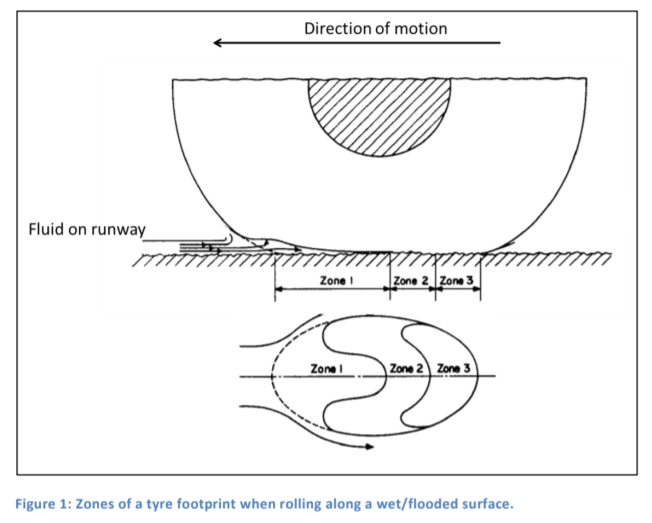
I don't know what you saw in training material and I certainly have absolutely no doubts about your sincerity, integrity, skills and professionalism. But you've given me nothing I can examine and I do need something a bit more to go on. I have seen some films of hydroplaning tests that may give that impression due to camera synchronisation artifacts. Tyres I have examined after rubber-reversion hydroplaning have mostly had single contact patch areas of rubber-reversion, in one case they had several, representing multiple events with patchy areas of shallow water and the operation of that anti-skid system. I've never seen any damage that would correspond to slow rotation whether forwards or backwards. Hot steam should not be acting at the front of the contact patch where the water is coming from, that's the cooled side. I've seen DFDR showing wheel rotation ceasing at a point corresponding (but not exactly, the data isn't that accurate) to the white marks of rubber-reversion hydroplaning starting. If your training film *told* you that these were the conditions of rubber-reversion hydroplaning, I can only say, your training film was wrong to do so and you should re-evaluate incorporating this material in your personal model of how things work. But give me some reasonable reference to support your position and I'll be happy to do the same. I completely agree with the technique of a firm landing and avoiding a 'greaser', though more for having the maximum stopping distance. Unless you have solid tyres, it shouldn't be making any difference to whether or not you hydroplane in the first place and won't prevent subsequent hydroplaning. I do not accept the existence of rubber-reversion hydroplaning without prolonged wheel lock. With the improvements to anti-skid systems in the early eighties it is hardly ever seen in large transports today, except with emergency locked wheel braking. I still see no reason to expect fairly high rates of blown tyres with hydroplaning large transports and anti-skid inoperative. But I'm guessing now that you had dry runways in mind. Certainly more than with anti-skid, but I'd expect the thermal fuse to do something most times before the tyre blows. I must confess I once hydroplaned a good two and half km in a lightly loaded condition (150 tonnes) - it was very interesting and quite concerning too - nice that I had more than 3 km available. I'd say the use of reversors with regard to rudder effectiveness would be type specific, but I would note that you are not left without directional control with loss of rudder effectiveness, you have differential reverse thrust available and the issue of prohibited n1/n2 blade flutter zones in reverse is best left for maintenance to deal with after you stop. In some large transports, failing to use reversors means you don't have any lift dumping, which is hardly helpful. Yes, speed, water depth and tyre pressure are considered factors, as well as surface texture. Screed surfaces greatly increase the water depth requirement, but are hardly used due to the stone throwing aspects and so on. Grooving does much the same thing, longitudinal is a hell of a lot smoother than crosswise and more durable. The essence of predicting commencement of total dynamic hydroplaning is Horne's formulae. dynamic hydroplane ground speed (knots) = 9 x tyre pressure (PSI)^-1. Load/weight makes no difference - for a typical F100, it's 146 knots. Robert Horne did about twenty years of experimental research on hydroplaning in the NASA, using full size gear on a test sled. In 1963 he thought the (reverted-rubber) cleaned skid phenomenon was due to water under high hydrodynamic pressures scouring the area, but with more research, came to understanding the steam aspect. Due to improved anti-skid systems, you hardly see it today - except with emergency systems that don't have effective anti-skid or defeat anti-skid. What really happens in rubber-reversion hydroplaning? You have up to three zones involved in hydroplaning. In total dynamic hydroplaning, the entire tyre is removed from contact with the underlying surface - the dynamic hydroplaning zone extends from the area of tyre contact with the water and there is neither a viscous hydroplaning zone nor a zone of surface contact (or a bow wave). In hydroplaning, this zone is always present , but its trailing edge moves forward, first being replaced by the viscous zone, then by the contact zone behind the viscous zone. As speed reduces, the contact zone increases in size, displacing both the viscous and dynamic zones until we have full contact again. Also, as speed decreases below total hydroplaning speed, a bow wave is formed as part of the dynamic hydroplaning zone. drawing: Gerad van Es, Netherlands Aerospace Centre. Zone borders change with conditions. Zones 1&2 reduced in R-R planing. In rubber-reversion, the wheel is locked and the area of the contact zone (the third zone) is heated whilst being supplied with water from the viscous zone, which is turned into steam. This can only - repeat - only - occur with the wheel locked. The reverted rubber tends to form a skirt about the water under the contact zone, retaining water to create steam and reducing friction in much the manner of a hovercraft. The steam is towards the rear of the tyres interaction with the water and the surface, not at the front. There just isn't a way to do it with a rotating tyre, forwards or backwards, because the conditions for it no longer exist - at least, in real aircraft so far. Maybe if you take things vastly outside of real world parameters you might be able to heat the whole tyre whilst it slowly moves in a forward rotation. And maybe you can drive it backwards and have the same thing happen. But that's so far beyond scope it isn't worth looking at. Films of total dynamic hydroplaning tests will often appear to show backwards movements as the wheel slows down to a stop (which it will do, if total dynamic conditions remain long enough and no one invents frictionless bearings) - it is due to the shutter synchronisation issue. It's like how you can use a stroboscope on a propellor when calibrating a tacho and have the propellor appear to move backward or stop. It isn't real, it is an illusion. I would like to say something about how to deal with hydroplaning. If a go-around isn't an option, reversers are a good option, provided you can maintain directional control (not prohibited by flight manual) - you can always retract them if you have to, but you can't apply them earlier than you did. But aerodynamic braking works, lift the nose up with lift dumpers to manual if you have them. As a matter of interest, you can usually tell with the combination of DFDR data and the weight and balance, not only if hydroplaning occurred, but what kind of hydroplaning too. Warm regards, Paul
-
Qantaslink Fokker 100 overrun - Newman, W.A.
saccani replied to onetrack's topic in Aircraft Incidents and Accidents
I'll let someone else say it; "Reverted-rubber aquaplaning. This occurs when a wheel 'locks up' (or stops rotating) [emphasis added] and is dragged across a wet surface, generating steam. The steam pressure lifts the tyre off the runway surface. Heat from the steam causes the rubber to revert to its unvulcanised state, leaving a black, gummy deposit of reverted rubber on the tyre. Reverted-rubber aquaplaning will also typically leave distinctive marks on the runway, with black marks on the edge of the contact patch and a clean section in the middle where the runway has effectively been steam cleaned. This type of aquaplaning can occur at any speed above about 20 knots and results in friction levels equivalent to an icy runway." - ATSB So I guess I'm not alone in my wacky ideas. Also take a look at page 16 on in this study; ntrs.nasa.gov/archive/nasa/casi.ntrs.nasa.gov/19680010151.pdf . I'm willing to be convinced of your thesis - do you have data to support your thesis? I'm not sure I understand your comments about ABS, discussion of the F100 system may shed light. In the Fokker 100, there are three modes of anti-skid operation; Touch down protection: All six pressure valves remain in the dump position until seven seconds after the ground/flight mode changes to ground mode, or any wheel reaches 20/40 mph (20 or 40 mph depends on mod status). You could apply full brake when landing and the wheels would have no braking applied. Lift dumpers (if available) should normally be manually deployed on wet runway, but ground mode is needed. Approx. 80 knots wheel rotation is also needed for auto deploy. Typically 7 seconds after touch down on a contaminated runway, 3 to 5 seconds after mode change before the brake pressure dump valves are released. Skid detector: Kicks in at 12 mph wheel rotation speed. Each wheel has deceleration monitored and excessive deceleration causes pressure release on that wheel to keep it from exceeding the skid threshold. Locked wheel prevention: Above 20 mph wheel speed, locked wheel circuits are in stand-by. If an outboard (inboard) wheel speed is 30% below the opposite outboard (inboard) wheel speed, a full pressure dump is applied to the wheel. This system is inhibited below 20 mph. In the F100, dependant on the ground/flight controller fitted, a guarded anti-skid off switch is on the pedestal next to the FO pitch trim wheel, allowing anti-skid disablement. The parking brake is not an emergency brake in the F100, it serves to retain applied brake pressure. Instead an alternate brake system will operate without pilot intervention if the primary brake system on that side fails. This isn't obvious except by the annunciator, almost full capability is retained, but each side is treated as one unit for anti-skid, instead of each wheel. I can see no reason to have tyres blowing fairly often with anti-skid inoperative. In this system, the anti-skid system allows brake application without wheel rotation. Locked wheel protection doesn't operate if both outboard (inboard) wheels are turning or not turning within 30% of each other - as may be the case with extreme hydroplaning. Application of brakes on touch down with aquaplaning can result in locked wheels from seven seconds after ground/flight enters ground mode until the aircraft stops. As in, it is possible, particularly if auto deploy is selected on lift dumpers, as they may fail to reach the 80 knot deploy threshold, before the brakes are applied, preventing it from happening. One reason why lift dumpers should be at manual for a wet runway. With regard to the "characteristic appearance", all my knowledge and experience says that is of an area of reverted-rubber corresponding to the contact patch of a locked wheel. I've never seen any data to support rotation of the wheel in reverted-rubber hydroplaning (let alone backward) and it is contrary to my experience in investigating such matters. What may sometimes occur is a patchy series of contaminations, causing multiple areas of reverted rubber, as the wheel spins and then locks again - this may perhaps give some the impression of rotation, but these are separate cases. But, as I say, I'm open to being convinced otherwise - though my previous experience and training says it is not so. Here is Michelin aircraft tyres take on hydroplaning; "10.3.4. Dynamic Hydroplaning is a high speed phenomenon which occurs on any surface and requires a minimum fluid thickness. 10.3.4.1. Considering the various fluids reasonably encountered by aircraft tires, slush is the most likely to cause dynamic hydroplaning. It is less dense than water, but is deeper due to its viscosity. Slush, along with snow or ice, deserves particular attention. 10.3.5. Viscous Hydroplaning results when a thin film of fluid (water) on the runway becomes a lubricant. It may mix with the contaminants present or the water alone may be sufficient if the surface texture of the runway is smooth as on a painted portion of the runway markings. Generally the irregular condition of the runway surface is sufficient to break up this film. 10.3.6. An aircraft tire experiencing hydroplaning may form an area of tread rubber reversion or skid burn in the tread due to lack of wheel rotation [emphasis added]. This area will be oval in shape similar to a flat spot. If the reinforcing ply (bias) or protector ply (radial) is not exposed the tire can be left in service. If any vibration resulting from the flat spot is acceptable, the tire can be left in service. NOTE: The most effective method to minimize the effects of water on traction is to reduce the water depth. Many airport runways are cross-grooved to improve water drainage." Kind regards, Paul -
Qantaslink Fokker 100 overrun - Newman, W.A.
saccani replied to onetrack's topic in Aircraft Incidents and Accidents
I don’t think you can get rubber reversion with dynamic hydroplaning, you need to lock the wheels to get rubber reversion hydroplaning - otherwise the necessary friction simply rotates the wheel. This is most commonly encountered when an aircraft is in dynamic hydroplane, ABS braking is ineffective and the parking/emergency brake is applied to manage a perceived service brake failure. You can see that it has happened by the steam cleaned wheel tracks on the runway as well as the chewed up tyres. Usually a secondary effect of locking the brakes is retraction of lift dumpers, after some type specific delay. So the sequence may be of heating the tyres first, retracting the lift dumpers and then continuing with locked wheels and less water displacement. -
Qantaslink Fokker 100 overrun - Newman, W.A.
saccani replied to onetrack's topic in Aircraft Incidents and Accidents
I would be surprised if Alliance avoid the use of reversers to save fuel - it increases maintenance costs when you use more braking. The fuel use is minuscule and at the lower end (idle reverse) there is absolutely no increase in fuel use. No economic reason to avoid their use. The procedure for this F100 operator is to use reversers when available. However, please note - reverse thrust is not considered in landing calculations, it is there for economic reasons, reduced wear and tear. Most of this operators F100 do not have auto brake (IIRC, NHY is ex Avianca and is not equipped), they do all have ABS. All the aircraft are equipped with auto deploying lift dumpers. Both reversers and lift dumpers will be ineffective if main wheels don’t reach a speed equivalent to aprox. 80 knots IIRC, as there is a logic box that mostly prevents them from operating in the air. The comments below are speculative. Two possible technical factors of relevance are a level of aquaplaning that prevents or delays sufficient main wheel speed to deploy armed or set lift dumpers and which prevents selection of reverse thrust - this can greatly increase the landing roll. A possible operational factor would be inadvertently landing long under challenging conditions. This operator is right on the ball with stabilised approaches and sticking to the numbers, I think it unlikely that a high approach speed would be a factor - unless they had concurrently dealt with a wind shear alert (not warning) during the approach, in which case they might be at the higher end of the tolerance. There is no PAPI and no precision approach for Newman, so vertical guidance is limited. It’s unlikely (I only mention it due to a lack of information on the circumstances), but sometimes in the Pilbara a wind shear event on finals with an attempted escape manoeuvre is so great that the aircraft still touches down from the go around. A previous Pilbara case of a dry microburst with an F100 bent the aeroplane, but there was no overrun. Conceivably, a different result with a contaminated runway could see an overrun. -
Welding instead of rivets
saccani replied to old man emu's topic in Aircraft Building and Design Discussion
!? That’s about the person doing the welding. I’m talking about the process control for manufacturing a particular structure using novel methods and design. -
Welding instead of rivets
saccani replied to old man emu's topic in Aircraft Building and Design Discussion
Nitrogen is an inert gas, inert gases need not be elemental and are often compound. You seem to be thinking of noble gases, which are highly unreactive and monatomic under normal conditions. All noble gases also form compounds, such as Argon Flourohydride, but under unusual conditions. Noble gases are a subset of inert gases.