Kyle Communications Posted November 26, 2020 Share Posted November 26, 2020 Bad SWR..not enough earth ground plane on the base of the antenna. Its RF getting up the nose of the mic or leads of the headsets Skyranger is fabric and alu tube..do you have at least 600x600 alu plate somewhere that the antenna is mounted on? 1 Link to comment Share on other sites More sharing options...
Ando Posted November 26, 2020 Share Posted November 26, 2020 18 hours ago, RFguy said: Some advice for the masses : RG400 (teflon ) is nice, but it wont make any difference to your radio signal. Zilch. nada. Cheap black coax RG58 from a reputable supplier is just fine... as long as the maximum operating temperature is < 80 deg C. That's the limitation . Advantages of the Teflon cable- survives very high temperatures, 200C deg all day and night , and 400C deg for a short period. Also, dont bother with double shielded cable. It's a con unless you are working in a very high tech laboratory. And needs different connectors. And stay away from single inner conductor cables , always use stranded inner conductor cables unless it doesnt move (or is restrained so it doesnt move) Dont squash the Teflon cable too much , it will cold flow, given time. Glen (yes I do this for a living) . Good to have you here buddy! Link to comment Share on other sites More sharing options...
jetboy Posted November 26, 2020 Share Posted November 26, 2020 18 hours ago, M61A1 said: Have you looked at adjusting the mic gain on the lightspeed headset? Can you set the Xcom GAIN level to a lower setting? Mic gain is adjustable as a menu setting in the Xcom, If I recall it was a trim adjustment in rear of Microair. You want this set in flight noise conditions, so the modulation when speaking forcibly just gets to 100%. I've made this adjustment heaps of times, changing from readability 3 to 5. Link to comment Share on other sites More sharing options...
Kyle Communications Posted November 27, 2020 Share Posted November 27, 2020 on the lightspeeds with a Xcom... you need to remove the mic muff and adjust the mic gain pot in the actual mic section. Typically it is turned all the way down then you adjust the mic gain on the Xcom to suit. The Lightspeeds seem to ahve a lot of audio out so you need to dampen it down Link to comment Share on other sites More sharing options...
Jabiru7252 Posted November 27, 2020 Share Posted November 27, 2020 Two ways noise gets into the radio. Via the antenna or via the power lead. Disconnect the antenna at the radio, if there is no change in noise, it's coming via the power lead. Maybe need an inline choke (easy to make). If the noise goes away, it's coming via the antenna which means you need to check your RF suppressors (if fitted) or fit some if not. That's how we handled this sort of stuff when I was an apprentice radio tech years ago, installing/servicing two way radios when they were as big as shoe boxes! Of coarse you first check all antenna and radio connections are clean and secure. Link to comment Share on other sites More sharing options...
RFguy Posted November 27, 2020 Share Posted November 27, 2020 some comments :, back from my hotnav. Don't press the transmit button on your VHF radio with no antenna connected. Not even for a millisecond. Don't power up a transponder with antenna disconnected. For modulation, with flight level noise, set your modulation up so when speaking in an assertive clear manner, modulation is > 90% at least 25 % of the time. Good talk power comes from clipping the voice peaks. HOWEVER- not too much gain that the background noise, without speaking, while transmitting, modulation should be less than 10% on average , if the noise cancelling mic on the headset is any good. This can only be ascertained with a modulation meter, BUT can be reasonably approximated with another monitoring your transmission. LIGHTSPEED - yeah sounds by those comments there is alot of excess audio available. Link to comment Share on other sites More sharing options...
spitfire Posted November 27, 2020 Author Share Posted November 27, 2020 Thanks for the responses guys, this may throw a bit more light on it, Skyranger has a larger than 600 x 600mm ali plate for the antenna. I promise not to disconnect antenna and transmit. I set the mike gain to what the light speed guys told me , all the way down and undo 1/4 turn , at least I think that’s what they said... Link to comment Share on other sites More sharing options...
Blueadventures Posted November 27, 2020 Share Posted November 27, 2020 50 minutes ago, spitfire said: Thanks for the responses guys, this may throw a bit more light on it, Skyranger has a larger than 600 x 600mm ali plate for the antenna. I promise not to disconnect antenna and transmit. I set the mike gain to what the light speed guys told me , all the way down and undo 1/4 turn , at least I think that’s what they said... For info I connect the earth plate to my neg on battery. Link to comment Share on other sites More sharing options...
Kyle Communications Posted November 27, 2020 Share Posted November 27, 2020 The earth plate should be connected to the frame of the aircraft even though its just tube as the more mass you can get attached to the earth the better On the lightspeed mine is turned all the way dow...not 1/4 turn on as I found the gain to be massive with the lightspeed. Then do the adjustment on the Xcom 1 Link to comment Share on other sites More sharing options...
RFguy Posted November 27, 2020 Share Posted November 27, 2020 Just to clarify = I think what Mark means when he says "the more mass you can get attached to the earth the better" - what he actually means is the MORE surface area of electrically conductive material , the better. Radio frequency (F) currents at VHF travel in the top 38 microns (0.038 mm) of a good conducting material. This means tube is the same as solid bar for RF. And foil is just as good as say, 1mm plate Lots of tube , like a lattice , truss structure is just as good as flat plate. Having the antenna mounted in an area of dense tube is as good as a small flat plate. if you use plate , it can be foil thickness..... U use copper or Aluminium tape, and also Aluminium flashing used for hoiuse costruction is one of the best methods of acheive good RF ground because it is thin (light) and wide (surface area) . Link to comment Share on other sites More sharing options...
FlyBoy1960 Posted November 27, 2020 Share Posted November 27, 2020 The problem I have seen with a lot of the foil type ground planes is that they deteriorate over time especially on a surface that can flex like a fabric aircraft and you can start to lose your grounding because it breaks away from the aerial base. On a composite aircraft, no problem but on a rag and tube aircraft you need to be more careful. The only reason they make aircraft out of metal any more is to get a good ground plane #$&^%@😁 Link to comment Share on other sites More sharing options...
Kyle Communications Posted November 27, 2020 Share Posted November 27, 2020 I have always hated the foil. Much prefer to use say 0.020 sheet as the antenna base can then bite into the alu without breaking through Link to comment Share on other sites More sharing options...
Kyle Communications Posted November 27, 2020 Share Posted November 27, 2020 Mobile One makes a aviation antenna that has a 1/4 wave stub antenna underneath it. It works..often used on the tailboom of trikes. I use one up at my farm on a post. I have a proper base station ground plane antenna now that will go up there. When you put the hole through the fuselage you would be best served to get some 20 thou sheet and make it at least 600 square or round if you can and shape it roughly to the inside contour of the skin and either glue it there or attach it somehow. It depends a lot on the antenna but as I said the more metal area you can get it will work better Link to comment Share on other sites More sharing options...
RFguy Posted November 28, 2020 Share Posted November 28, 2020 (edited) Hi Mark yeah I tend to agree too flimsy (foil too thin) and its trouble to use. If you need to support the antenna base, then certainly the foil is too thin. Certainly copper foil is pretty good when thin, but heavy. The metal needs to extend ideally at least 1/4 wave or 640 mm away from the antenna base. But it does not require a continuous sheet. 600x600 is not enough on a non conductive body . you need ground plane at least two opposite directions of about 0.64 meter length. 100x100 is no different really to 600x600. The full length of ~ 1200mm square is required. A 100x100 mounting plate on a metal body is fine (because the rag and tube or fuselage sheet will do the rest. A 100x100 mounting plate on a non conductive body, together with two x 640mm lengths of foil going in opposite directions is good. It does not have to be a continuous sheet. tape or tube extending is fine. A large continuous sheet AND then tube extending to at least 1 meter from the antenna base is even better. Just remember everyone, once it is > 0.038mm thick, that's enough from an electrical POV (mechanical practicalities aside) . Aluminium flashing I use- but Ally tape or copper tape is just fine for ground plane extension. The stuff is from Bunnings is called WEATHEFLASH and is 0.3mm thick, 150mm wide. Edited November 28, 2020 by RFguy Link to comment Share on other sites More sharing options...
RFguy Posted November 28, 2020 Share Posted November 28, 2020 (continued from previous post) Lyle, 600x600 might be convenient to buy but the 600 x600 size is not magic, its actually too small. You need 640mm distance from the antenna base to cover down to 118 MHz- that means 1280mm square Iin line with what Mark said folding the sheet over, you ideally want a 1280x1280 sheet (say 1200 x1200 to make it easy) and this can be folded on the edges- does NOT have to be a bit flat plate. 1200x1200 sheet would be fine. You can, and I would recommend for a NON METAL plane, do what Jabiru did in their fins, a centre fed dipole : The only thing is the elements need to be wide (surface area) to get good bandwidth. I would make it with INCH wide foil/thin sheet . The Dipole would be about 1100 mm to go roughly in the middle of the band , split in the middle where the coax is applied. Again , it needs to be wide strip. Wide strip helps the antenna cover a wide range of freqencies Also you cannot just "make" a half wave end feed, it is a different impedance. Link to comment Share on other sites More sharing options...
Kyle Communications Posted November 28, 2020 Share Posted November 28, 2020 1/4 wave in free space at 118 mhz is 635 mm so anything above that size will be ok...obviously the more you can get the better and yes you can run radials out from this to increas the size. Its all relative really on how you do it to fit your particular aircraft. The one thing to always remember is more is better. So make it as big as you can. Also remember too that the more one sided your counterpoise is this will also offset the radiation pattern that you are transmitting so try to keep it symetrical if you want roughly the same signal output in all directions. If you want to do some quick numbers the formula is 300 divided by the frequency in megaherts then divded by 4 ..this will give you the numbers in free space for a 1/4 wave but if you want to know the length in coax then you multiply by the velocity factor of the coax. usually you will do this in the centre of the frequency band or on a specific frequency if you want it "tuned" to a point Link to comment Share on other sites More sharing options...
Kyle Communications Posted November 28, 2020 Share Posted November 28, 2020 The problen is you just cant get a lot of this inside many aircraft so you just try to get as much as you can inside. I have seen a few dipoles inside some Jab aircraft but these dont have very good radiation patterns it again depends on the orientation of the antenns. Its all a compromise in composite aircraft. All alu aircraft of course its simple. Link to comment Share on other sites More sharing options...
RFguy Posted November 28, 2020 Share Posted November 28, 2020 Lyle, A would NOT recommend any sort of loaded Helical whip. Helical whips are very narrow band and the requirement is WIDE band... And with the quarter wavelength of 640mm at lowest frequency, if you put the whip in the middle of the band , say 124 MHz, a 590mm long whip really isnt too long..... There are other options you can build (I can guide you) for any specific airplane or mechanical requirement. Lyle what is the aircraft, and what is the body ? For a non metal body plane- The fin is a good place to put it, keeps it away from the intercom and headsets ! AND there are horizontal antennas that radiate vertically. For a non metal body plane, I would recommend a centre fed dipole (like jab) or a delta/quad loop. These have the minimum problem with ground return and ground currents Link to comment Share on other sites More sharing options...
Kyle Communications Posted November 28, 2020 Share Posted November 28, 2020 Aaron...just remember your headset will be directly inline and pretty close the RF coming off the antenna. Internal antennas not only are difficult to do properly but can have a lot of RF interference into your electronics 1 Link to comment Share on other sites More sharing options...
RFguy Posted November 28, 2020 Share Posted November 28, 2020 Mark is right. Also remember in a non metal skinned or composite body that control cables and rods will conduct RF and modify the antenna radiation pattern, the metal cables and rods become part of the antenna and will carry RF energy back to the cockpit... Link to comment Share on other sites More sharing options...
RFguy Posted November 28, 2020 Share Posted November 28, 2020 Arron25, actually the quad will be good -enough omni- it depends what shape you built them..... The control rods and cabls will be main influence. However with say 600 sides on the quad, it might be just too big in the empenage. The quad needs a bit over 1 wavelength of wire, any closed shape, preferably not a convex. And it also needs a 75 ohm quarter wave matching section. Or a series 68 is ohm resistor in series which would keep the radio happy over the bandwidth at the cost of 50% of efficiency... anyway, that's just one idea if it fits The biggest issue is BANDWIDTH. the only way to keeo the radio happy probably requires some losses (resistors) Radiating elements that are 'thick' or wide (large surface area have the most bandwidth. If you made your quad with inch wide tape, the bandwidth would be excellent. (use with 75 ohm matching section at middle of band) . The aviation band 118-136 is a wide bandwidth considering the physical constraints on the antennas. -glen Link to comment Share on other sites More sharing options...
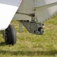
RFguy Posted November 28, 2020 Share Posted November 28, 2020 Aaron, that white radomed antenna will be just fine with 600mm RADIUS of ground plane (of tube or sheet) , or several strips of wide copper or Alluminium tape or thick foil / flashing - four is good each 640mm long, inch to 4 inches wide. from the antenna mounting base. Antennas on these ships are a compromise. It's important to remember that ideal , perfect omni directional radiation patterns can rarely be achieved due to the interaction with the body of the aircraft and flight controls. Link to comment Share on other sites More sharing options...
Roscoe Posted November 28, 2020 Share Posted November 28, 2020 And just for something different if all else fails, photo is a Windshield Antenna kit. One end to a Handheld comm, the rubber duck antenna on the other end and it sticks anywhere on a plexiglass surface. I have one, not tried in flight yet, but in the Jab you can attach the antenna to a rear window. Just a thought!! Link to comment Share on other sites More sharing options...
RFguy Posted November 28, 2020 Share Posted November 28, 2020 no ground plane, likely to be extremely poor result, and put RF into all your intercoms, electronic instruments, EFIS etc portable radios only work on VHF with a rubber duck because YOU form the other half of the antenna. if you need a emergency portable antenna just attach the other end of a piece of coax to a length of thick wire, 1180mm long, cut the wire in the middle, hang the wire vertical ish, and feed inner conductor of the coax cable to the top half of the cable and the shield to the lower half of the coax. Link to comment Share on other sites More sharing options...
RFguy Posted November 28, 2020 Share Posted November 28, 2020 Microairs. yeah, send me your dead Microairs. Either for me to fix (fixed price repair, I'll have to figure out what that will be , probably something like $100 + shipping ), or I will buy them dead. What I need is to see a few more than just a couple so far in the flesh. I need to see what the full spread of problems are. And indeed if they are worth carrying on with. I've done a bit of reading, seems to be a couple of systematic design problems . and vulnerabilities that are maybe easily solved. Down the track, MAYBE I will try and re jig my digital radio product into something that can fit in a 3" hole. And it needs to be dragged down a bit in build cost. Of course it doesnt need dual 10 Gbit optical interfaces.... That radio has 8 parallel receivers with priority ducking, one transmitter, single antenna connector , noise cancelling against ignition static, and radio and antenna self test. However, you still should have a 2nd radio when sh1t happens and anywhere near circuits. Link to comment Share on other sites More sharing options...
Recommended Posts
Create an account or sign in to comment
You need to be a member in order to leave a comment
Create an account
Sign up for a new account in our community. It's easy!
Register a new accountSign in
Already have an account? Sign in here.
Sign In Now