

3rd harmonic
-
Posts
52 -
Joined
-
Last visited
-
Days Won
1
Content Type
Profiles
Forums
Gallery
Downloads
Blogs
Events
Store
Aircraft
Resources
Tutorials
Articles
Classifieds
Movies
Books
Community Map
Quizzes
Videos Directory
Posts posted by 3rd harmonic
-
-
One of the Sporty's with a 912ULS at Aldinga had a partial engine failure reduced power through lack of fuel flow.
The return spring on the diaphragm pump was the issue, the spring could be broken/cracked and still work somewhat.
They do a lot of hours and the pump may not have been changed even when the engine was changed due to expired TBO.
One of the penumatic grease guns we use at work (broken spring) had similar symptoms, it would work sometimes?!
-
 1
1
-
-
I have seen D connectors where the pin has been pushed back into the plug. In my context that is 8 channels of balanced audio on a DB25 using the TASCAM pinout - a faulty pin can result in losing half or 6dB of the signal, either the +hot or -cold.
Looking at the Dynon installation manual and DB37 connector pinout there are 2x V+ power inputs (pins 1 and 20) and 4x ground pins (pins 21, 22, 23 and 24) for redundancy.
Power and ground are right next to each other and the pins are also pretty close inside D connectors and it is very easy for even a single strand to come adrift and create an intermittent short circuit which could easily generate the funny resets ect
I would open up the back shell on the DB37 plug and check that as a first port of call...
-
1
-
-
Hi Skip,
It would appear logically that after multiple different units being installed/uninstalled the original issue may not have been resolved...
I would be looking specifically at the grounding and or negative return to the battery.
Some bits of gear will do all kinds of funny things when the ground is lost, intermittent or high impedance.
If the main ground which is on the DB37 connector (I think) is faulty then current may be making its way back via the shields on the data Comms connections causing corrupted data.
A 4-wire ohm meter is the weapon of choice to do this that can accurately measure fractions of an Ohm (egg 0.01)
Check the plug, pins and crimps.
With the plug disconnected and no power applied, check the resistance back to the battery.
Aggravate, vibrate, tap things while doing these resistance checks
If the resistance changes or goes higher than 0.5 ohms then that could cause those issues...
It's a bit hard to explain exactly how to go about this, but hopefully that gives you some idea...
-
 2
2
-
 1
1
-
-
N'interrompez jamais un ennemi qui est en train de faire un erreur ! Napoleon
'Never interrupt an enemy that is making a mistake!'
One country in particular will stand to benefit from US division and isolationism.
All they have to do is watch and wait...
-
1
-
-
Nice work on the AEG batteries and welding helmet it helps keeps the MONEYBOX full rather than empty😉!! It's the kind of stuff I do likewise..
I've got an 6Ah AEG battery that a mate gave me which unfortunately got flooded overnight when it rained (when it did actually rain some years ago) the cells are fine but the multi layer BMS PCB suffered electrolytic corrosion and is buggered!
High temperatures are a fairly big deal for LiMnCO2 or LiFePO4 batteries, the BMS will often just disconnect the pack for safety.
They especially DO NOT like being charged while hot, as that generates more heat internally - much better to let the batteries cool down before wacking them on charge.
Yeah, those 12v LiFePO4 batteries are great for caravans/campers ect but a serious stand alone power system with a 24v or 48v bank is better resolved by using individual 3.2v block cells with separate BMS and cell balancing system (I was a CEC accredited designer of solar off grid stand alone power systems for a while)
-
1
-
1
-
-
9 hours ago, langted said:
So, if one wanted to use this port for a maintenance charge, it clearly won't work since the master relay itself poses a load that would screw up the charger capacity and voltage sensing. But for learning the avionics, it'll do. And it'd be ok for a bulk charge.
Some understanding of contemporary 3-stage lead-acid battery charging might help:
1. Bulk stage: (constant current) the charger pushes the voltage higher at the max current it can source (or is selected) 5, 10, 20A ect
2 Absorb stage: (constant voltage) when the voltage gets to 14.2-14.5v, rather than pumping out max amps to push the voltage higher, the charger holds the battery voltage constant. The current into the battery should taper off as the charge is absorbed though ALL the material on the plates.
3. Float or maintenance stage: (constant voltage) generally after a perset time at the Absorb level the charger will drop the voltage back to around 13.2-13.8v, the current into the battery should be pretty low at this point. Any additional load across the battery can then be supplied by the charger while the battery is 'floating'.
For lead acid batteries temperature strongly affects the charging end point voltages and this needs to be compensated for - correct charging of larger battery banks in fixed installations generally always has a temp sensor on the cells.
Especially for batteries that are not used all the time, it is IMPERATIVE that they are charged to the absorb level regularly to avoid the plates becoming 'suphated'
----
To answer the question, a bench supply or an RV power supply will just float the battery and supply any load with master switch on which will work fine, although without any absorb stage.
The regulators on traditional aircraft alternators are pretty low tech, generally they only float charge at no more than 13.8v and there isn't any basic temperature compensation that most automotive ones have featured since the 1980s. This tends to result in undercharging, suphation and early battery failure.
-
1
-
-
Those RV wall power supplies are much like a 13.8V bench supply with some current limiting at maybe 20-40A. But a 13.8v bench supply would be fine anyway, you ain't going to get 60A flowing even if can do it... Essentially, if the battery is in a reasonable state of charge at 12.5V, even 0.25ohm on a 1-2m of your connection cable to the battery which could be 8-10 AWG will limit the current into the battery by (13.8-12.5)/0.25 = 5.2A
It will gulp abit of current initially, after some minutes it will push the battery volts up to the float level (13.8v) and the draw will be minimal, plus whatever is turned on in the plane.
-
1
-
-
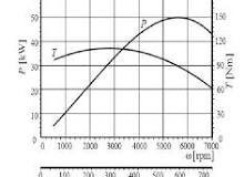
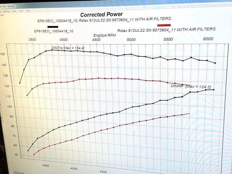
Yeah, his engines are bloody awesome! That graph I picked out compares the Edge performance 915 to a standard 912ULS. If you look elsewhere in his photos the Edge performance version of a standard 912, but injected, has a flat 130NM torque curve from 3700rpm upwards and is good for an extra 10-12hp. Because the motor breathing is so much better and the fueling is more consistent it uses a fair amount less L/hr for the same hp.
-
On 04/03/2025 at 9:26 AM, skippydiesel said:
In general the greatest load/demand on your engine is from start of Ground Run to top of Climb Out.
The ideal rpm setting to address this demand, will be one that is past peak torque (in round figures - minimum 5200 RPM for Rotax 9's).
Torque is a measure of the engines ability to do work, usually illustrated as a curve (see below).
If your engine is operating ahead of peak torque, any reduction in rpm caused by additional load, will be accommodated by an increase in torque & no additional stress on the engine.
Few pilots can maintain a constant load on their engine, in other than perfectly smooth flying conditions, so fluctuations in load are the norm.
Operating at or below peak torque is likly to place unnecessary stress on your engine and will reduce aircraft performance when the inevitable increase in load occurs.
Rotax recomend that its 9 series engined be operated in the range of 5200-5800 rpm for TO (minimum 5200 rpm).

If you follow the EDGE PERFORMANCE FB feed, he often puts up VERY interesting dyno graphs of the engines he's produced or overhauled.
These are ACTUAL measured results, not theoretical speculation.
This one is particularly instructive, for the 912ULS the TORQUE curve is in reality pretty much flat above 4700RPM, HP increases are really due to increasing RPM.
Over proping the engine with too coarse a pitch, will tend to 'slug' the engine, much like changing into a higher gear on a (manual) car at too lower a speed. It definitely not going to cause any damage because the engine can't do any more than the available torque at that rpm, but the horsepower developed will be down on what would otherwise be possible.
I experienced this directly in the VH Sports-star with a CS prop, on one circuit when i forgot to set the prop rpm up to max, which as i recall was 5800rpm corresponding to 'full fine' pitch.
We were still climbing away OK, but i was indeed 'slugging' the engine at about 4800rpm! Once that was pointed out, a quick flick of the dial allowed the motor to really scream at full noise and the performance change was quite noticeable...
-
1
-
-
That list of items that are considered 'Line Maintenance' is pretty extensive and most of the items listed there could easily get you into big trouble and/or damage the aircraft if you didn't know what you were doing. I think they make some passing comment about people being competent to perform the task, but who decides that? Some people who might quite competent or experienced pilots, wouldn't know the difference between a left or right handed screwdriver! I would back my engineering/mechanical skills over my piloting skills every time, but that's just down to lack of experience in the latter. In a different life would love to have been a flight engineer - on those big complicated aircraft they are REALLY the ones in control 😉
-
1
-
 1
1
-
-
On 02/03/2025 at 1:41 PM, Moneybox said:
Somebody asked once what the yellow lever was for. It's the hydraulic park-brake. Apply foot pressure and raise the yellow lever.
Yes, the park brakes were lock-wired down/off in the sporty's I flew which were used for instruction, i assume to avoid the chance of landing with the brakes on - probably a good idea with low time students. The inflight adjustable prop looks like a nice simple system to operate, assuming it's setup well and you keep an eye on the RPM. You'll have to let us know how it how goes when you (finally) do get it in the air!
-
1
-
-
On 01/03/2025 at 10:22 AM, Moneybox said:
He went through the inflight adjustable propeller manual checking for service life etc. He updated the logbook and maintenance manual with all work carried out and replacement parts fitted.
What CS adjustable prop do you have?
I've have a fair amount of flying in the sporty's which are heap of fun. The RaAus 24 registered ones at Aldinga had a standard 912uls with a fixed pitch woodcomp prop. But at one point they were booked up /out of action so I had a go in a VH registered one that has a 915 turbo with CS adjustable prop. I was instructed not to use full power because it really wasn't nessecesary (it wasn't), then on one circuit we did wind it out to full wack. The motor was SCREAMING and we were going like a cut snake up at a very steep angle!
Definitely it would be cheaper in your own aircraft, so that seems like a good plan...
-
Yep, definitely no owner maintenance for hire/reward and in the RAAus context that would be mainly flight training aircraft which can be hired out for solo time. I think that's fair enough actually, the expectation rightly should be that aircraft used to carry/train members of the public are maintained by professionals at arms length and not modified from the factory spec.
-
2
-
-
The 19 reg aircraft that I am trying to fix up has wings that can be removed for transport/storage. To remove or reattach them legitimately and sign that off you have to be an L1. Like moneybox I have a lot of engineering experience and skills but had never worked on an aircraft at that stage. So I went through the process, enrolled in the online course did lot of reading of the FAA reference material and maintenance rules and passed the exam.
The pass mark is high and some of the questions were pretty obtuse, but managed to get it done. I did that some time after I got my RaAus licence.
I stand to be corrected but I think that 24 reg factory build aircraft have to be maintained by an L2 / LAME or they lose the factory built status.
-
This accident has to qualify as one of the most brutal EVER! Obviously, there was decision making process (or lack there of) that led to the A/C ending up where it did. Happen to be watching ABCnews24 and they had live footage from a BBC reporter showing the accident scene this morning. The concrete slabs on top of the dirt mound which the localised antenna structure were mounted looked to be at least 0.6m thick by several meters square. Maybe there should be concrete slabs at the end of every runway, that would focus the mind of pilots so they are on-speed and on-point OR decide to go-around early? Crying out loud...
-
1
-
 1
1
-
-
Yeah, it was sadly mentioned on this site previously that Ray was no longer with us. When I visited him at Camden there was A LOT of aircraft in various states of repair. I was hoping that thier might be a garage sale of the stuff as I was looking for some Morgan related items, I'm sure it wouldn't be so easy to deal with tidying that all up...
-
Adelaide really SHOULD have a rail link to the airport, it's only a relatively short distance of a few of km's from the main rail corridor at Mile end which is a fairly short distance to the CBD, in contrast to Melbourne which is a very looong way away. In my mind this seems like low hanging fruit! The the south rd upgrade using tunnel boring machines is going to cost mega bucks, but rail hasn't rated a mention...
-
1
-
-
Most of these permanent magnet alternators which are found on motorcycles and aero engine are a shunt type regulator. Essentially the control element 'shunts' current to ground to hold the voltage down as the output increases with RPM. A capacitor is a good idea on the output as this will tend to bypass any switching noise or spikes to ground, rather than relying on the battery which may not be effective. However large electrolytic's offen have a fairly low self-resonant frequency that may be only a 400-500Hz, above which the capacitor is behaves like an inductor. To ensure the capacitor remains capacitive a 1uf polypropylene film cap can be used to bypass the electrolytics....
A large filter capacitor means the alternator can effectively run the electrical loads without a battery connected.
-
1
-
-
On 02/12/2024 at 8:49 AM, T510 said:
Is it possible to do endorsements in aircraft I can not fly solo?
Adelaide biplanes will definitely let you hire & fly solo once endorsed.
Under RAAus, the tailwheel endorsement is competency based, essentially you keep practicing and learning until they are happy that you can handle the aircraft in a variety of conditions, then they sign off your log book. I would say that Aldinga can be pretty windy and changeable at times which does give you exposure to conditions that aren't straight forward and that does help challenge the skills. If you look at the Adelaide biplanes FB page just last month they sent a 16 Y/O solo in the champ and a 18 Y/O gained pilot certificate (tail-wheel) which is pretty awesome. The pricing is online: https://adelaidebiplanes.com.au/pricing/
-
 1
1
-
-
It is interstate from Ballarat, but I'll put in shout out for Adelaide biplane at Aldinga. Most of the aircraft they have are tailwheel. Raaus: Cubcrafters sports cub, Aeronca Champ.
VH: Decathlon, Tigermoth, 2nd Champ, Great lakes biplane, Waco biplane.
I did my endorsement in the sports cub which is very versatile and lots of fun.
Martin from the UK ex BA who owns the joint, is very experienced and runs a tight ship.
Aldinga is well setup for tailwheel with grass runways on all 4 points of the compass.
They regularly graduate young Raaus pilots who have only flown tailwheel, which really sets them up for a great career with stick and rudder skills ..
A
-
2
-
 1
1
-
-
Yeah, i know they won't share the current evenly, although 2x devices on the same die at the same temp won't be too bad, yes it is really about redundancy.
Parallel MOSFET's will because the negative temp Coefficient, BJT's with positive temp won't hence the emitter resistors that give some local current feedback.
As generally seen in audio amplifier output stages (and i have repaired MANY!!)...
The VISHAY bolt on devices would be a good option, abit of a heat sink would be needed.
Shottky diodes don't like high reverse voltages, 60V PIV would be nice maybe.
-
1
-
-
On 17/03/2024 at 1:43 PM, RFguy said:
take a good look at the fuel injection pump current requirements under various condix, they can pull a fair bit, and that you might have BOTH pumps on due to design (or error ?)
Given that good quality, sealed non liquid electrolyte batteries generally do not have sudden failures, it's probably a good option as a power source. a strong schottky diode or MOSFET schottky implementation with some sort of current limit would be a simple and reliable option. A big schottky with say only 20V 30V reverse barrier will be pretty low voltage drop. maybe something like 12 or 14 gauge wire will serve as a current limit....maybe aim for wire resistance = diode drop under normal conditions, as a starting point. that will be fine as long as the charging system gets up to 14.4 , 14.6V region
Good point regarding the fuel pumps - yes normal fuel pump powered off the normal bus and the reserve pump powered off the ECU bus behind a diode on the small standby battery. I've used these shottky diodes for a caravan 12V system where i wanted isolation from different charging sources, with both diodes in the package in parallel, for a very low forward voltage drop
VISHAY DUAL 150V 80A DIODE PACKAGE
In an aircraft i'd be looking at 2x packages, for a total of 4x diodes in parallel.
The DA42 accident is really just a lesson in redundancy engineering that could have EASILY been avoided IMO. I'd say they had a partially sulphated, poorly charged battery that collapsed under load when the L/G was retracted, of course a backup ECU battery modification was suggested AFTER the accident.
Whoever came up with the electrical system design obviously didn't have much imagination...
Unfortunately battery voltage post start and alternator current output check ironically will look artificially GOOD with a sulphated battery. As the voltage will come up quickly and the charge current will be low with the inability of the battery to absorb any charge. A load test will quickly show a battery with high internal impedance.
I don't think there's been any official findings on the UL power velocity twin accident ref reg: N106VT??
-
Yeah, look as good as points based magnetos for the time when they were the best thing available, life has moved on in the last 100 years. Solid state capacitor discharge ignitions are still simple enough, but miles better. Every lawnmower, small engine, motorcycle and of course the Rotax 91x series are a testament to that - even if carby is completely gummed up after years of non use generally you'll still get a spark that doesn't fail.
Having said that the 2hp 60yr old Briggs&Stratton points motor on my cement mixer hasn't failed yet even though it lives outside with a bag over it...
-
17 hours ago, RFguy said:
Mike I gather the UL system has one alternator and one ship battery. usually the single alternator is doing double duty and I think that's a bad idea, since the engine systems are not isolated from the troubles and switches and breakers and ge-finger trouble of the user.... The only way to really get away from it is a 2nd power source., or perhaps an independent feed from the battery with its own isolation relay (or a 2nd battery only for the UL so that buys you an hour etc, and some switch that you can cut over the Ul to main ship battery- but then you have a single failure point in the cabin maybe....
so, some thought required to escape the single power feed issue.
The UL systems having its own feed from the battery and own isolation switch etc is probably the simplist.
I have been thinking about my UL engine and I agree, RF guy this is likely the best approach. The greatest danger with ECU's that need power for the engine to run is not the alternator failing as you will have some time to find somewhere to land - but a short to ground. I found that out the hard way with a 1980s BMW E30 323 coupe I used to own. Ill advisedly put a standard size battery in rather than the correct DIN66 battery, which wasn't quite as tall. This worked ok for abit until I went over a decent bump and the + battery post shorted out on the bonnet. The car stopped running instantly and I pulled off the road while fumbling for the bonnet released on the passenger side as the battery was fizzing out acid into the engine bay like crazy.
My thought was to have a smaller separate battery that ONLY feeds the ECU and have the isolated from the normal battery with a very heavy duty Schottky diode. Ordinarily the batteries will be charged in parallel, but a short on main bus won't take down the ECU and cause an immediate engine failure.
-
1
-
Random Low Fuel Pressure Indication.
in Engines and Props
Posted
Looks like my memory wasn't exactly accurate, found on the RAAus accident/occurrence page:
OCC0871 28/12/2016
OCCURRENCE DETAILS SUBMITTED TO RAAUS: DEFECT: Failure of the outlet valve in the fuel pump caused a loss of power on take-off. Take-off aborted and aircraft landed on remaining runway. Part of the valve is pressed into the body of the pump. The part pressed into the body came out after - the outlet valve remained open which caused a drop in the fuel pressure. Note: the standby electric pump was 'On' however also lost pressure through this failed valve. OUTCOME: This aircraft is an LSA and as such this defect was reported to the manufacturer. Technical Manager reviewed the aircraft logbooks which was provided by the maintainer. The aircraft logbook showed that it has high hours and appears the fuel pump has failed due to fair wear and tear.