Hi,
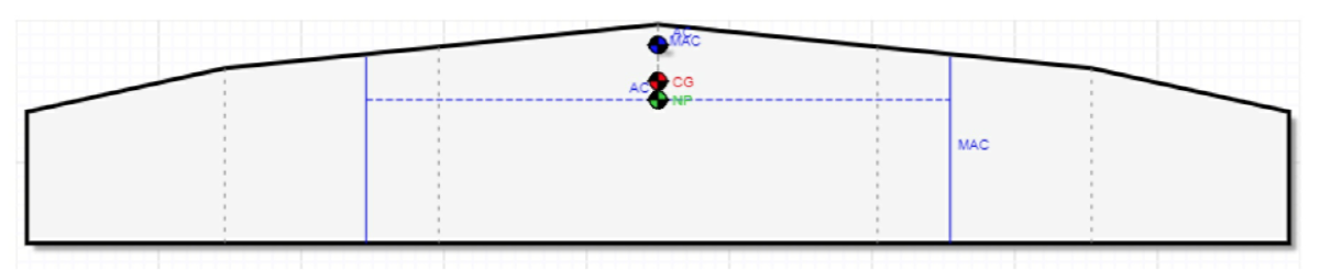
Things have gone silent on my end for a while - some minor medical issues, but mostly a lot of head-scratching over the design of the wings. I had NO IDEA how difficult designing a wing would be. And a Flea wing especially, because it is made up of separate panels, with hinges and pivot points. Sourcing the correct hinges has been a nightmare - found some some this morning which I think will do nicely. (Naturally) I opted for a swept wing rather than a rectangular one, so first I had to calculate the centre of pressure before I could position the spar to which the pivot is attached, and then I had to update the spreadsheet to check on the optimum CG.
That done, I had to calculate the size of each rib, and the position of the cut-outs for the two spars. Cutting the ribs was easy, of course. Next up was cutting the cradles for each of the wing sections, so that the ribs would be perfectly spaced, and vertical, with the required 4 deg dihedral.
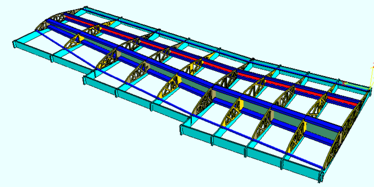
I trial fitted everything, and when satisfied that it all fitted together nicely, bonded the spar caps (blue in the screenshot above). I checked that the trailing edge (4mm glass fibre rod) was straight (it was). I then threaded the 16mm Tassie Oak dowel for the leading edge. Also straight, and a nice fit. I then bonded the LE in.
Next job is to bond in the shear webs. They are already cut, so it will be just a matter of slapping on the West System epoxy, and clamping. There are also two 19mm x 19mm drag/anti-drag spars which, although the router cut the holes in the ribs in the correct places, it can only cut at 90 deg, so I have to "angle" the holes so that the spars will fit. And then bond them in place. By this time, the wing should be pretty rigid.
I also had to design the wing attachment hardware. The rear wing consists of two halves, separated by the width of the aft fuselage (about 135mm). The inner rib is reinforced, and bolted to a metal attachment on the fuselage. The outer attach point is at the first hinge point. This hardware has been drawn, but not cut yet.
Next came the drawing of the wing sheeting. Not as easy as it might sound because of the swept wing. But I've completed that now also. The rear wing will require three full sheets of 1.5mm ply.
As you can see - a lot of time at the computer.
So much for the wing.
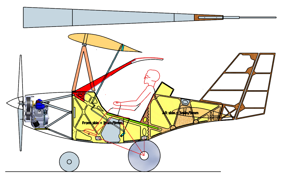
I have decided (based on the astute comments here on the forum) that placing the gas tank in front of the firewall - while convenient, because I could use a regular 20 litre gas tank from Bunnings and some fittings from boat shops, this was a terrible position not only because of the proximity to the hot engine, but also in terms of the change in CG as the gas gets used. So I've moved it to inside the fuselage directly on the CG.
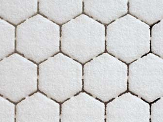
The grey area inside the fuselage in the screenshot above is the new position for the gas tank, with a filler cap jutting through the side just under the pilot's knees, out of the way. About 18 litres (about three hours flight time). I'll have to fabricate it. I thought of plywood sealed with vinylester, but it strikes me that I have a whole box of 3D Core foam, which looks like this:
Extremely light, very easy to cut on the router, and simple to laminate with a layer or two of vinylester and glassfibre. I'll prototype the tank out of cardboard, and then Bunnings plywood before I commit to the actual tank.
So that's what I've been up to since last time I wrote. As usual, comments welcome.
Regards,
Duncan


 That done, I had to calculate the size of each rib, and the position of the cut-outs for the two spars. Cutting the ribs was easy, of course. Next up was cutting the cradles for each of the wing sections, so that the ribs would be perfectly spaced, and vertical, with the required 4 deg dihedral.