BC0979
-
Posts
81 -
Joined
-
Last visited
Content Type
Profiles
Forums
Gallery
Downloads
Blogs
Events
Store
Aircraft
Resources
Tutorials
Articles
Classifieds
Movies
Books
Community Map
Quizzes
Videos Directory
Everything posted by BC0979
-
Has anyone successfully fabricated half doors for their Savannah S? Would you please share your design Thank you
-
Savannah S vg's have alignment nubs that fit into the pre drilled holes at the leading edge so holding them in place for 10 seconds isn't very difficult
-
Great input Guys! I have bare aluminum (no paint) under the VGs. I did see that the StolSpeed website offers double sided tape but as stated earlier, not the right size for ICP VGs. I did not see that the "manual" recommended super glue. If I use super glue, I could remove the VG with a heat gun if and when a replacement is required.
-
Thanks to all of you I am almost there....😁 After I get my Savannah S assembled at the field, I will install the little plastic VG pieces. I didn't want to transport the wing with them installed to prevent possible damage. So the question is, what do I use to install these little plastic VG pieces? Is there a clear glue the you recommend?
-
These jury struts are a pain in the you know what, LOL Right side took over 5 hrs but the left side was done in 1.5 hrs. Not my best work but they are installed

-
Yes, I am in Florida, USA so FlyBoy is correct. I am required to have 7" minimum ground clearance. 15X6-6 tire deflated plus the bottoming out of the nose gear to the stops. I will need to check this. I fly off a grass field so nothing will save me if I bury the nose gear in a gopher hole.... Thanks again for all the input.
-
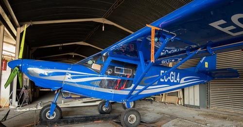
The Facebook link was just to show a pic of a Savannah with an extremely extended nose gear. Attached is the pic.
-
https://www.facebook.com/share/p/wr9TsRM1hdWVLSR1/?mibextid=oFDknk Here's a link to what we were discussing about the nose gear and what I should not do
-
I also read the Stolspeed.com prop study that you all suggested. That guy does get work. His study uncovered that the cruise speed remains essentially the same for all props he tested but climb rate would be affected from going down to a 68 from a 71. I can live with the that since I this is not a Stol competition plane
-
Update: Viking will replace the 71" with a 68" prop. They will also supply a nose gear spacer. I may change the main gear tires to make up for the nose gear spacer after a few crow hops.
-
I truly appreciate all the input. I acknowledge that I am installing a non-rotax engine and the elevation of the prop shaft may be different. I understand the ramifications of raising up just the nose gear. I contacted a guy that purchased all three Savannah S kits which included the 912 and prop. ICP sold him a 175cm(68.9") prop. I received 180cm(70.9") which yields 3.5" of ground clearance. If I convert to 22" tires(all three) from the 15" tires that would yield another 3.5" and bankrupt me at the same time 😂
-
Yes, Viking 130. So a 70" prop with a rotax 912 on 15x6 tires will give you how much ground clearance???? I fly off of a grass field so I am concerned about ground clearance.
-
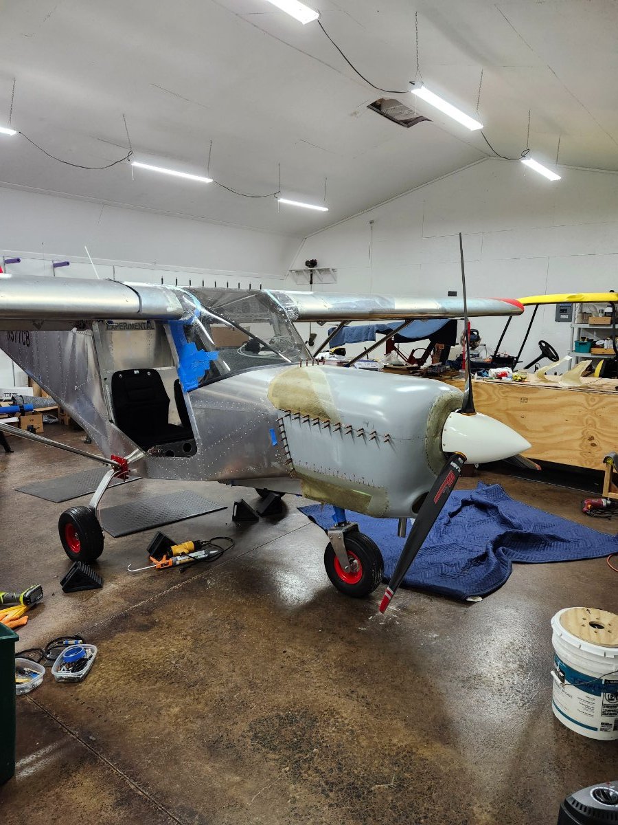
Hello to all... What prop diameters are you turning? And do you have the required minimum 7" ground clearance with the 15x6-6 tires? I just mounted my prop and discovered that I only have 3.5" of ground clearance. I think I have the wrong prop. The nose fork will not accommodate a taller tire.
-
Agreed, the people on this forum are great people
-
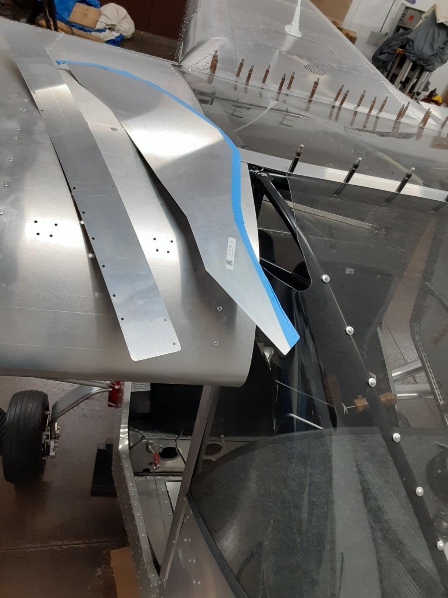
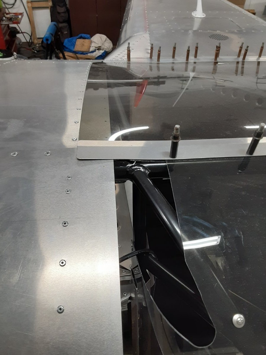
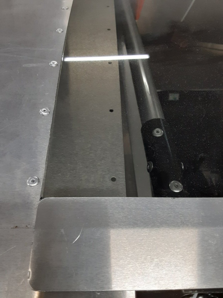
Bodie Thanks for the pics. They are very helpful. No I have not installed the extensions as yet, been wrestling with it, then I get frustrated and stop. The roof also has me puzzled as to why the pre drilled holes are at the wing skin edge and the precut lexan overlaps so much. The construction manual has been very helpful...LOL
-
Before I go hacking on these miscellaneous parts I thought it wise to ask .... Is there a trick to installing these two skin extensions? The blue tape, so I don't scratch my lexan. I know that there is a rubber edge trim that was supplied. Then there's the roof panel. The prepunched holes are quite a ways in from the edge. Flutter issue in the making? Any insight would be greatly appreciated Bryan
-
I downloaded the maintenance manual as you suggested. Thank you, thank you Very difficult to find things on their website 😕 The person that made the construction manual must have done the website too LOL I removed the 20mm long machine screw/dip stick and syringed the excess out 😁
-
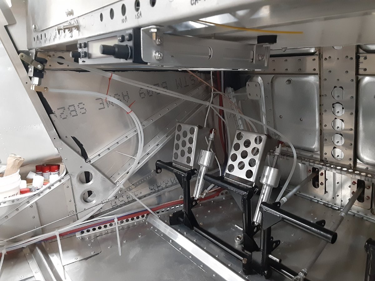
Ahhh.. reservoir This is the first time for me with his type of cylinder. My other plane had closed, non reservoir cylinders with bleeders so you could pressure bleed from either end. I did not see any info on my construction manual on the air space and did not know about registration either. Apparently there isn't any issue with our park brake located above the toe brake cylinders cuz I would think gravity would cause the fluid to drain down to the toe brakes and eventually empty out/bleed off. I quess I should use a syringe and remove a few CC's and make a 20mm dip stick,LOL Thank you all for the insight
-
Just filled my brake lines with Shimano brake fluid which is mineral based and was recommended by my dealer. Got all the connector leaks stopped except for the very top of both cylinders.🤨 The bleed Allen screw is as tight as I can get it. It is so tight that it will rotate the top plate of the cylinder. Maybe it takes time for the top seal to expand from the newly installed mineral oil?
-
IBob and Bodie Thank you! This is exactly the help I needed.
-
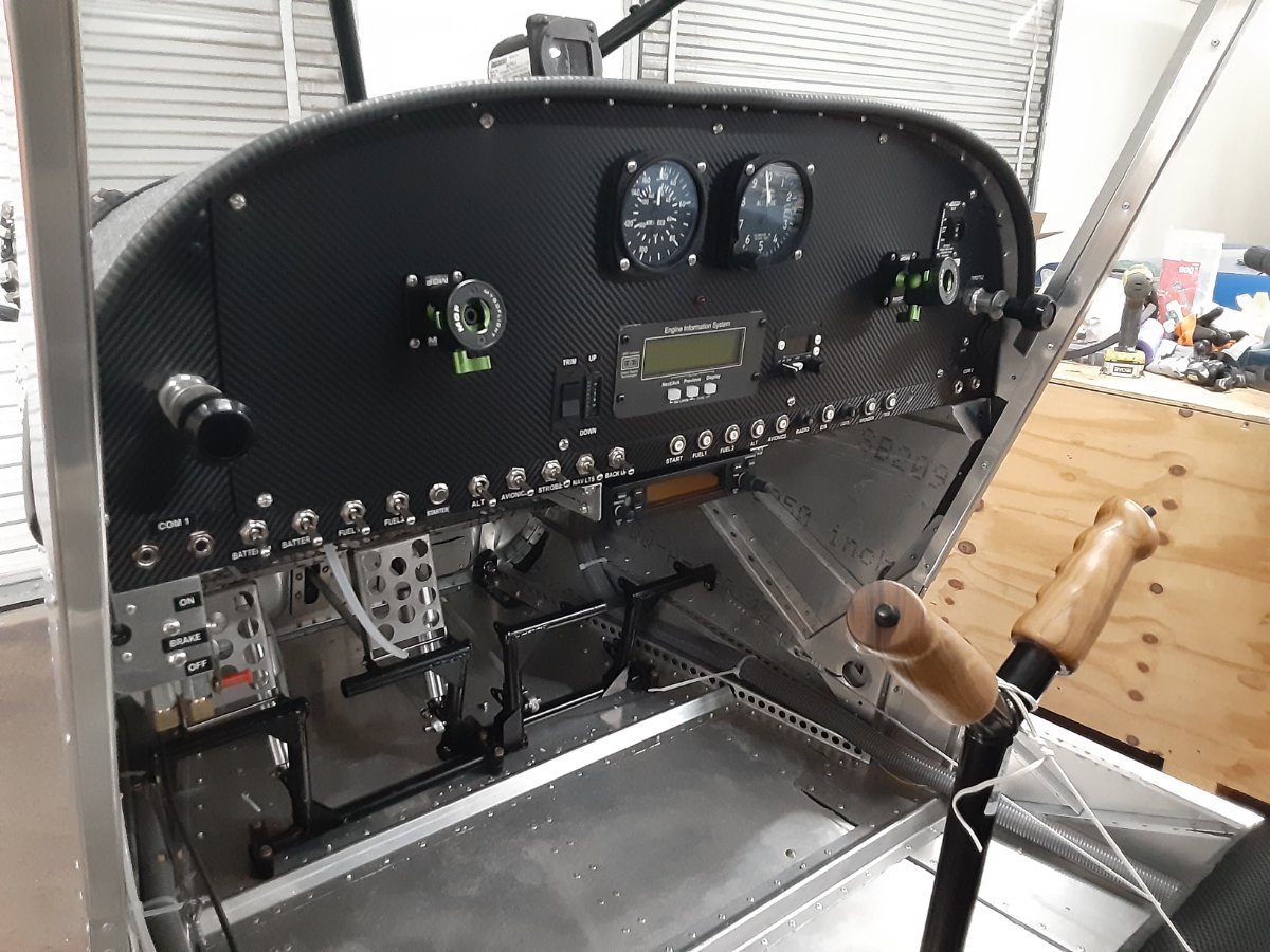
Just to close out this thread, I decided on natural wood grips. I am not talented in wood carving so I found a guy in Oregon that makes them. Thanks for all the valuable input
-
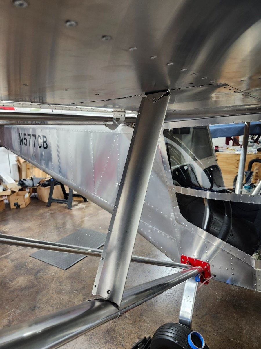
Would someone help me out by sending me pictures of the jury strut installed on the Savannah S. The "manual' is not helping, 😂 I am more familiar with round tubes for the jury struts, the S has a formed aluminum strut SA202/203, SN451/452 bracket mounted on the wing bottom, and SN450 which is "wrapped around" the strut? Uncertain about using rivet nuts and screws to secure as opposed to pins (better shear strength) THANK YOU Bryan
-
What did you use? ICP carpet kit?
-
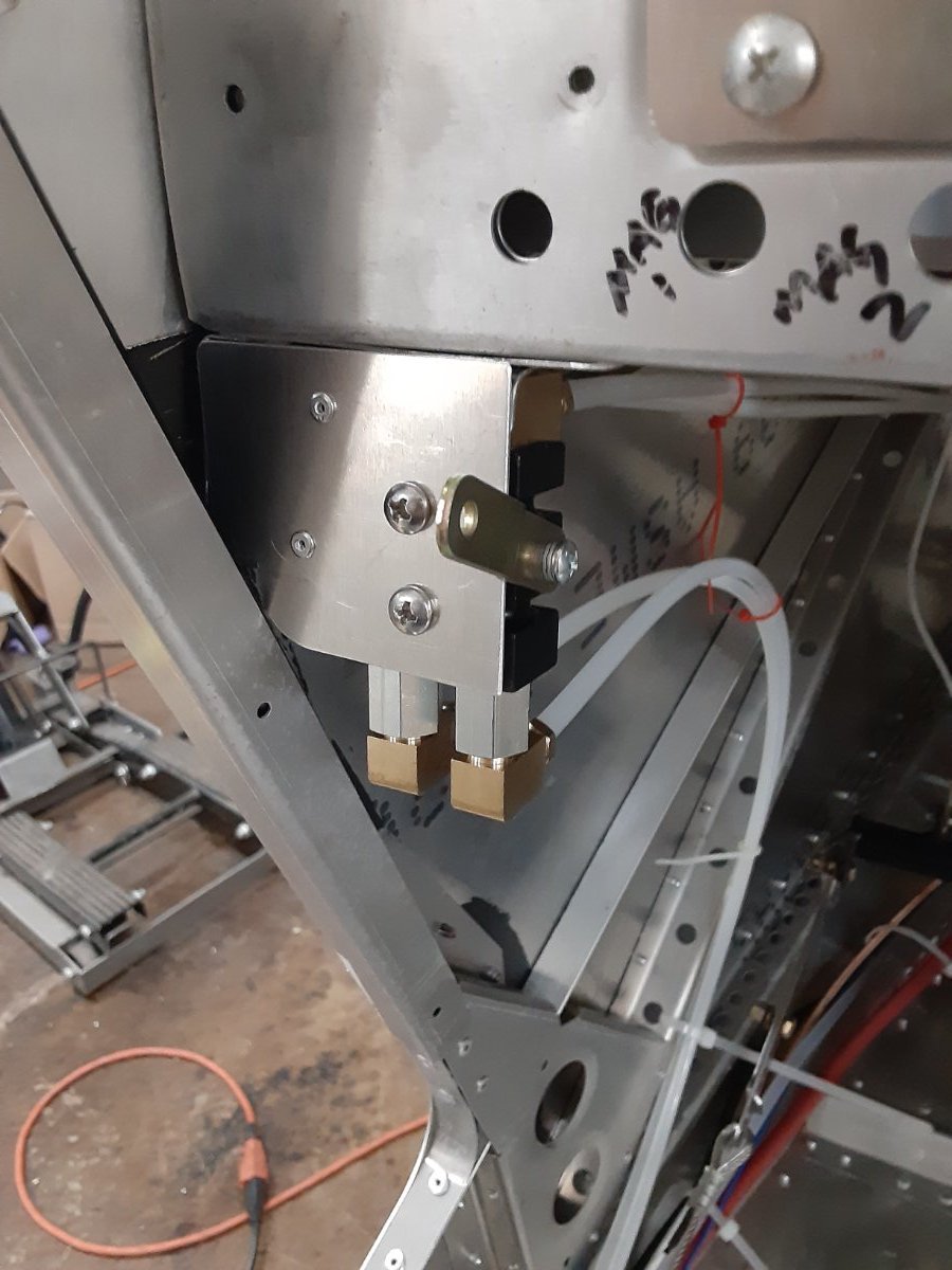
IBob, Thanks to you, I installed the park brake today 😁
-
IBob, I can do the same with the Matco. Lever up or down for brakes set or brakes off. Thanks for the pic of your panel.