rtfm Posted April 23, 2014 Author Share Posted April 23, 2014 Correct. wheel fairings, very clean fuse. However, the rear wing is a lifting surface, not a stab. It is set to one degree lower incidence than the front, and (of course) sits in the front wing downwash. X-Plane predicts a six degree difference in AoA which agrees very well with NACA papers I've read on downwash angles. At takeoff, the rear wing produces about 120lbs of lift. During cruise, this decreases to about 25lbs @120kts, and about 10lbs of lift at 135kts (WOT). This is due both to downwash from the front wing, and increased pitching moment as speed increases. With this configuration (ie large wing in front, smaller wing in rear) I end up (essentially) with a mono-wing at cruise speeds with the rear wing acting as a h-stab and adding about 10lbs of drag but no negative lift. At TO and stall, however, lifting duties are fairly shared. Best of both worlds? This shift in relative lift is partly responsible for the large performance envelope. Duncan Link to comment Share on other sites More sharing options...
Bob Llewellyn Posted April 23, 2014 Share Posted April 23, 2014 Correct. wheel fairings, very clean fuse. However, the rear wing is a lifting surface, not a stab. It is set to one degree lower incidence than the front, and (of course) sits in the front wing downwash. X-Plane predicts a six degree difference in AoA which agrees very well with NACA papers I've read on downwash angles.At takeoff, the rear wing produces about 120lbs of lift. During cruise, this decreases to about 25lbs @120kts, and about 10lbs of lift at 135kts (WOT). This is due both to downwash from the front wing, and increased pitching moment as speed increases. With this configuration (ie large wing in front, smaller wing in rear) I end up (essentially) with a mono-wing at cruise speeds with the rear wing acting as a h-stab and adding about 10lbs of drag but no negative lift. At TO and stall, however, lifting duties are fairly shared. Best of both worlds? This shift in relative lift is partly responsible for the large performance envelope. Duncan Makes good sense to me. Er, the downwash is a distributed ellipse, and your HW looks to have enough span to stick outside the region normally considered (by NACA) for the HS... you may end up with a tad more lift on the rear stablewinger than you expect. This is what prototypes are for, of course! :o) It's normal to call the smaller horizontal surface a stab, whether it lifts up or down... in high wing layouts, the rear surface may lift both ways in a normal flight. A lot of the 1930-1940's French load carriers used a large, high-aspect-ratio rear surface, often with endplate fins. They were pretty efficient, too... If you let me know the horizontal separation of the centres of lift of the wing and rear surface, and the CG possie (both vertical and horizontal), I can have a stab at a stability curve too, if you like. Link to comment Share on other sites More sharing options...
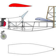
rtfm Posted April 23, 2014 Author Share Posted April 23, 2014 Two sketches (from X-Plane) showing the horizontal and vertical separation of the wings. Datum: Spinner bulkhead Wing1 MAC (ft) 2.63 Wing1 CP from datum (ft) 2.86 Wing1 AR 6.82 Wing1 Area (ft^2) 42.56 Wing2 MAC (ft) 2.09 Wing2 CP from datum (ft) 9.09 Wing2 AR 7.53 Wing2 Area (ft^2) 30.05 Distance between the two Acs 6.23 Total wing area 72.61 Distance between W1 & W2 Acs 6.23 Side view: http://1drv.ms/1hh0taD Top view: http://1drv.ms/1hh0DP9 Link to comment Share on other sites More sharing options...
Bob Llewellyn Posted April 23, 2014 Share Posted April 23, 2014 Two sketches (from X-Plane) showing the horizontal and vertical separation of the wings.Datum: Spinner bulkhead Wing1 MAC (ft) 2.63 Wing1 CP from datum (ft) 2.86 Wing1 AR 6.82 Wing1 Area (ft^2) 42.56 Wing2 MAC (ft) 2.09 Wing2 CP from datum (ft) 9.09 Wing2 AR 7.53 Wing2 Area (ft^2) 30.05 Distance between the two Acs 6.23 Total wing area 72.61 Distance between W1 & W2 Acs 6.23 Side view: http://1drv.ms/1hh0taD Top view: http://1drv.ms/1hh0DP9 ta... just had a school conveyancing meeting, I'll muck around with this tomorrow. Cheers, Bob Link to comment Share on other sites More sharing options...
Bob Llewellyn Posted April 24, 2014 Share Posted April 24, 2014 Hi,Gosh, I turn my back at return to see you hard at it. Good on you... I have to just sit back and gaze in wonder at all this. Fascinating, but completely beyond me. You mentioned spinner size once or twice. I favour a large spinner (currently looking at 14.5") but this is not set in stone. It just looks nice. Some design targets: Stall 43kts Cruise 135kts My engine produces 50hp @ 3600rpm, and is fitted with a 1.6:1 PSRU. I trust these specs line up OK with your prop tinkering? Regards, Duncan A larger spinner will generally allow a broader speed range from a fixed pitch prop; and, provided it's not too sharp, reduces the overall fuselage drag quite a bit. The old Albatros biplanes (WW1) has pretty effective spinners, but since the jet age came along, people make spinners too sharp... Link to comment Share on other sites More sharing options...
rtfm Posted April 24, 2014 Author Share Posted April 24, 2014 Hi, I see what you mean. Looks a but bulky, but I can see how this would be effective. I'll have to start drawing to see what I can come up with... Duncan Link to comment Share on other sites More sharing options...
Bob Llewellyn Posted April 24, 2014 Share Posted April 24, 2014 Hi,I see what you mean. Looks a but bulky, but I can see how this would be effective. I'll have to start drawing to see what I can come up with... Duncan The front of the lowest-drag (incomressible flow) shape known - the teardrop - is a hemisphere; and the hemispherical nose on the hubs of Hamilton Standard props was actually very effective at keeping up the cooling air velocity. The Albatross solution put most of the hemisphere in the fuselage shape, but there's no reason you can't put more of it in front of the prop. It'll look a tad unconventional, but should add measurably to the prop thrust. 1 Link to comment Share on other sites More sharing options...
SDQDI Posted April 24, 2014 Share Posted April 24, 2014 I don't mean to be a lurker but I am really enjoying watching you and this thread advance Duncan . It looks to be a neat eye catching design. Keep the posts coming. P.S. Bob I love seeing the technical lingo explained in simple English very interesting:spot on: I skip through other technical stuff that uses BIG words:duck for cover:and probably miss a lot of interesting stuff but your info in this thread is understandable even for a farm boy like me:outback: keep it coming 2 Link to comment Share on other sites More sharing options...
Bob Llewellyn Posted April 25, 2014 Share Posted April 25, 2014 I don't mean to be a lurker but I am really enjoying watching you and this thread advance Duncan .It looks to be a neat eye catching design. Keep the posts coming. P.S. Bob I love seeing the technical lingo explained in simple English very interesting:spot on: I skip through other technical stuff that uses BIG words:duck for cover:and probably miss a lot of interesting stuff but your info in this thread is understandable even for a farm boy like me:outback: keep it coming No worries... I'm working up another serve, as the family allows :o) 2 Link to comment Share on other sites More sharing options...
Bob Llewellyn Posted April 29, 2014 Share Posted April 29, 2014 Back again! Based on the idea of trading off takeoff to gain top speed, I removed propellor that wasn't doing so much for top speed - i.e. outboards - and added propellor in the area that's stalled under static conditions, and working at top speed. The result looks like something you'd find inside a frozen lolly, or a bit like some WW2 german bomber props; starting from the tip, it tapers out from 2" to 3.25" at 50% span, then more steeply to 4.8" @ 19% span. I also changed to a quasi-linear twist distribution, which did not very much (but simplifies analysis a bit). This lot gives prop #9, which loses about 1/3 of the takeoff thrust, but extends the redline (donk) speed to ~109kts, and is still giving useful thrust at 130kts. The analysis showed that the tips were a bit lazy, so I added some tip advance (overall twist still linear, so it added all the way in, but by smaller increments). This gives prop #10, which loses out to prop #9 up to ~112kt, but extends the donk redline to ~115kt, and so the top-end thrust. Based on your drag curves, will this give you the Vh you're after? ps spent time rejigging analysis for extended speed range, more useful output; that, and life, got in the way :o)... still planning to fidget with stability stuff... Prop #8-10.pdf Prop #8-10.pdf Prop #8-10.pdf Link to comment Share on other sites More sharing options...
rtfm Posted April 29, 2014 Author Share Posted April 29, 2014 Hi Bob, No worries about taking your time. Family/life are priorities. I had estimated a top speed of 135kts, so this looks right on the money. I don't really have any drag curves to speak of, to be honest. Just a bag of wishes and an evolving airframe. Duncan Link to comment Share on other sites More sharing options...
Mark11 Posted April 29, 2014 Share Posted April 29, 2014 Toowomba to Brisbane is only 1hr 36mins drive (127km) and $15 on the greyhound bus.... Maybe a meeting is in order... I'll ask a dumb question - why not 65hp engine? Like a 582 Rotax. I have Xplane - how can we try and fly yours? Can we download it? Link to comment Share on other sites More sharing options...
rtfm Posted April 29, 2014 Author Share Posted April 29, 2014 Hi Mark, I'd be very happy to have you drop by the workshop when the plane is looking a bit more "respectable". There's a lot of mess at the moment, but I'm in the middle of adding the final touches to the plug so that i can make molds of it. That will happen in the next couple of weeks. After that, I'll be vacuum infusing actual parts - which ought to be great fun. You could arrive and give me some builder assistance for the day. I'd enjoy that. Yes, the model is available for download here on the X-Plane site. Here's the link... http://forums.x-plane.org/index.php?app=downloads&showfile=22694 Duncan 1 Link to comment Share on other sites More sharing options...
Bob Llewellyn Posted April 29, 2014 Share Posted April 29, 2014 Hi Bob,No worries about taking your time. Family/life are priorities. I had estimated a top speed of 135kts, so this looks right on the money. I don't really have any drag curves to speak of, to be honest. Just a bag of wishes and an evolving airframe. Duncan Here's what my performance estimate gives with Prop #10- it's a bit disappointing (118kt Vh), I think because the slipstream velocity figures I used in the first one were too low. HOWEVER! note that retracting the gear gives 128kt Vh. I realise that retracting U/C with sensible-sized wheels into a small aeroplane is a pain... perhaps a viable alternative would be to fit the spats with doors, so that the wheels are entirely enclosed in cruise? When this was done to the first BD-4 in Oz, the cruise gain was startling; and failure to retract the (balsa) doors was not a major catastrophe... There should be a tad more to come from the prop, though I'm not sure it's much without your TOR becoming silly. Perhaps reducing the diameter will give you 120kt+ Vh, as is... Rough Performance Estimates #2.pdf Rough Performance Estimates #2.pdf Rough Performance Estimates #2.pdf Link to comment Share on other sites More sharing options...
rtfm Posted April 29, 2014 Author Share Posted April 29, 2014 Cheers mate. You've been a star. So - I'm going to be limited to 118kts? Bugger. Anyway - that's a lot faster on 50hp than most people would expect. Question: Do you actually MAKE the props, or just design them? Actually, I was considering exactly your suggestion re: fully enclosed wheels. But I gave up on the idea, because I figured it would make very little difference. But if there is an increase in top end - it might be worthwhile. Pity about retracts, though. I don't think there's any space for them. Besides, I wouldn't know how to build them... Regards, Duncan Link to comment Share on other sites More sharing options...
Bob Llewellyn Posted April 30, 2014 Share Posted April 30, 2014 Cheers mate. You've been a star.So - I'm going to be limited to 118kts? Bugger. Anyway - that's a lot faster on 50hp than most people would expect. Question: Do you actually MAKE the props, or just design them? Actually, I was considering exactly your suggestion re: fully enclosed wheels. But I gave up on the idea, because I figured it would make very little difference. But if there is an increase in top end - it might be worthwhile. Pity about retracts, though. I don't think there's any space for them. Besides, I wouldn't know how to build them... Regards, Duncan I've been working on this software for yonks, in order to be able to make props that do what they are advertised to do. Due to the CASA Review of Regs, I am now back at university, with a family, and very little income. So progress is slow. I'm still determined, so I may have started making props by the time you're ready to go Enclosing the wheels should pay ~5kts for your juggernaut Link to comment Share on other sites More sharing options...
rtfm Posted April 30, 2014 Author Share Posted April 30, 2014 Cool. 5 kts is a lot for just enclosing the tyres. And good luck with the studies. I'll no doubt ne in contact closer to the time Regards, and thanks, Duncan Link to comment Share on other sites More sharing options...
Recommended Posts
Create an account or sign in to comment
You need to be a member in order to leave a comment
Create an account
Sign up for a new account in our community. It's easy!
Register a new accountSign in
Already have an account? Sign in here.
Sign In Now