Leaderboard


Popular Content
Showing content with the highest reputation since 07/01/11 in Aircraft
-
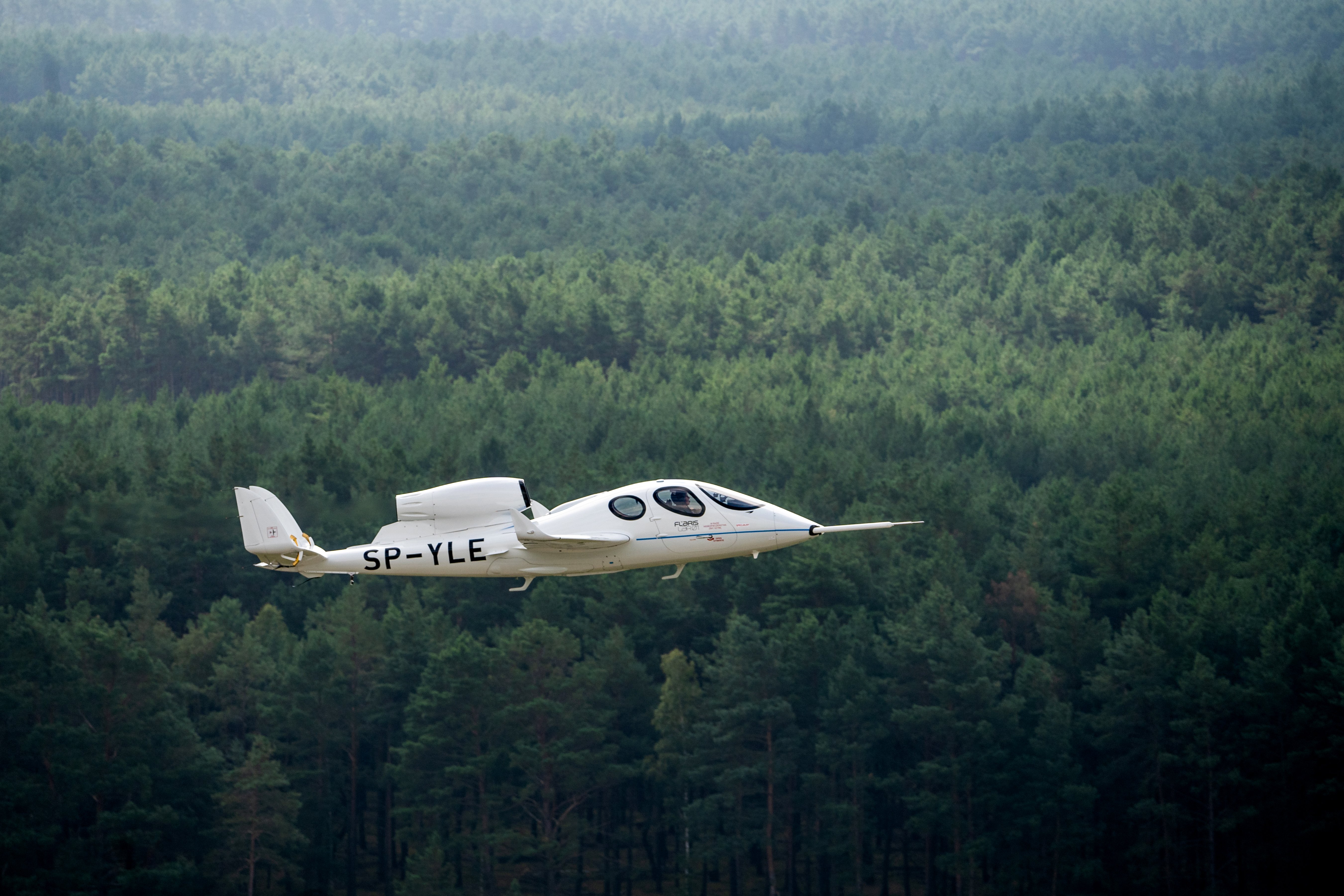 The Flaris LAR01 is a Polish five-seat very light jet intended for general aviation use. It is made largely of carbon fiber reinforced polymers and powered by a single turbojet engine – the production version of the LAR01 is to be powered by a single Williams FJ33-5A engine. The LAR01 is intended to be affordable and accessible to individual private owners. Proposed uses for it include air taxi operations, personal transport, emergency medical service and aerial surveillance , as well as its potential modification into an unmanned aerial vehicle (UAV). The LAR01 has been optimized for use by private pilots. Where possible, the cockpit is deliberately designed to mimic that of a traditional car. The designers intend to provide removable. Elliptical wings for the aircraft; this measure is to enable the type to be readily parked within typical garages; sections of the tailplane can be similarly detached for the same purpose. Fuel is housed within a tank mounted on the fuselage, deliberately avoiding the use of the wings for fuel storage. The LAR01 is also reported as being relatively easy to control. Various features for safety and convenience are to be incorporated into the LAR01's design. Unlike many jet-powered aircraft, it is claimed to be readily capable of being operable from unpaved runways and grass strips. For safety purposes, the LAR01 has been designed to use a ballistic rescue parachute system, a parachute being installed within the tail , which is intended to assist in the safe recovery of the aircraft. It can be equipped with various models of Garmin glass cockpit . An electric de-icing system is also fitted. Under 3 mln $ aircraft is forecast to have direct operating costs (fuel, maintenance and insurance) of $450 per hour and have a Garmin G600 TXi flight deck. It should cruise at 430 kn (796 km/h), have a range of 1,900 nm (3,519 km) with a MTOW of 1,500 kg (3,300 lb), and will be able to take off and land on grass airstrips and short runways of less than 250 m (820 ft).4 points
 -
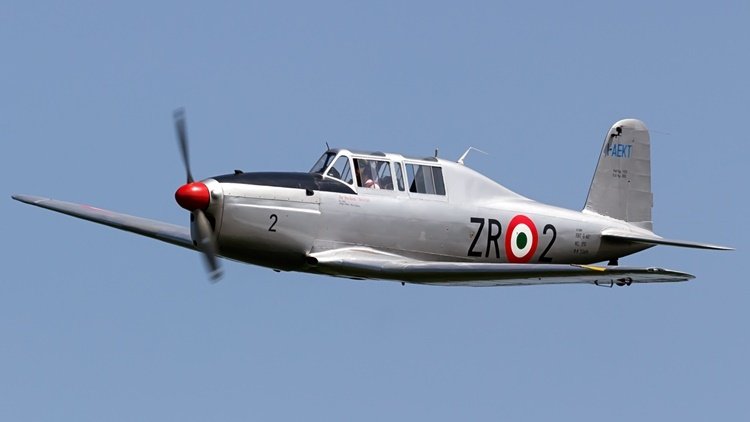 The G.46 was a conventional, low-wing monoplane with tailwheel undercarriage, the main units of which retracted inwards. The pilot and instructor sat in tandem under a long canopy. The first prototype, powered by a 205 hp (153 kW) Alfa Romeo 115-Ibis engine, made its maiden flight on 25 June 1947. Testing revealed excellent flying characteristics and suitability for aerobatics, and the type was ordered into production. Apart from the 150 ordered by the Aeronautica Militare, 70 aircraft were exported, to Austria, Argentina and Syria. Variants G.46-1B two-seater with Alfa Romeo 115bis engine, one prototype and initial production of 25 for the Italian Air Force. G.46-2B two-seater with de Havilland Gipsy Queen engine for the Argentine Air Force, 70 built with an additional 12 for the Syrian Air Force. G.46-3B two-seater with Alfa Romeo 115ter engine for the Italian Air Force, 25 built. G.46-4B two-seater with Alfa Romeo 115ter engine for the Italian Air Force, 55 built. G.46-5B two-seat navigation trainer (prototype only) G.46-4A single-seater with Alfa Romeo 115ter engine for the Italian Air Force, 35 built.3 points
 -
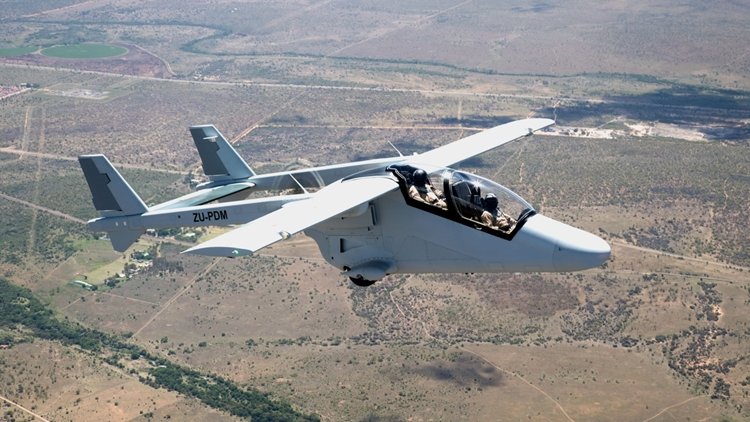 Mwari is a new light, multirole aircraft being developed by Paramount Group for armed forces across the globe. It is a military variant of the Advanced High Performance Reconnaissance Light Aircraft (AHRLAC). The Mwari project was unveiled in May 2016. Paramount and Boeing made a cooperation agreement in September 2014 for collaborating on specific projects to be implemented in future. The agreement was extended in May 2016 to jointly develop an advanced mission system for the Mwari aircraft. . The cost-effective Mwari multirole aircraft can be deployed in border patrol, counter insurgency missions, forward air control, forward airdrop and resupply, armed reconnaissance, and electronic intelligence (ELINT) and communication intelligence (COMINT) missions. Other mission capabilities will include internal security, disaster management and maritime patrol. Incorporating a twin-boom design, the Mwari aircraft will feature airframe constructed using meal and composite materials. The longitudinal booms at empennage feature a pair of vertical stabilisers joined by a horizontal stabiliser. The high-wing design will improve visibility for the crew, while allowing operations from unprepared airfields. The modular design will also support the integration of different mission systems for a range of military operations. The aircraft will have a length of 10.5m, wing span of 12m and a height of 4m. The maximum take-off weight of the aircraft is 3,800kg and maximum payload capacity with full fuel load will be more than 800kg.3 points
 -
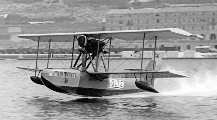 The CANT 10 was a flying boat airliner produced in Italy in the 1920s. It was a conventional biplane design with single-bay, unstaggered wings of equal span, having seating for four passengers within the hull, while the pilot sat in an open cockpit. The engine was mounted in pusher configuration in the interplane gap. CANT 10 flying boats were used by Società Italiana Servizi Aerei for over a decade, linking destinations in the Adriatic Sea. Two CANT 10ters were used by a company called TAXI AEREI in Buenos Aires, operating flights from the River Plate. One of them was lost in an accident and the other one was bought by the Paraguayan government for the Naval Aviation in 1929; it was used as a transport during the Chaco War and was withdrawn from use in 1933. A total of 18 CANT 10's were built.3 points
 -
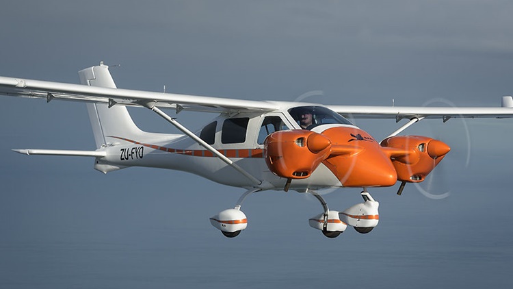 Len and Les Alford of Jabiru Aircraft Southern Africa are the South African dealers for Jabiru. They approached Jabiru in 2012 suggesting there was a market for a twin engine Jabiru in Africa. They explained that parts of Africa are best flown over at a great heights, and the prevalence of wild animals and AK47s tends to make flyers nervous about outfield landings. The conclusion…two engines would be nice. The project was always intended to be a joint development and aimed at the South African market. Jabiru had conjured the concept of a twin for some time but could not face up to the complexity generated by hanging the engines off the wings. This would have meant going back to basics on wing structure and all the difficulties of fire-proofing the wings, etc. Another physical difficulty was the engine pods completely obstructed the entry and exit points to the cabin. These considerations gave birth to the idea of mounting the engines on a short canard mounted on the firewall. Some quick calculations on the weight and balance weren’t too frightening and Jabiru was able to get the propellers quite close together to reduce the amount of asymmetric thrust on one engine. The issue of opening the doors against the engine pods was resolved and the design evolved from there. Jabiru’s John Farmer got to work making a streamlined nose for a J430 airplane and the two engine pods. Jabiru’s engineer, Tom Ferguson, was given the task of testing the supporting structure for the engines. As usual, most of the structure was built in composite with aluminum connections to the engines. The firewall structure of the J430 is unchanged and the nose wheel remains in its normal position. This is a relatively simple bolt-on modification. When the structure was finished and the molds were complete, the project was shipped to South Africa where the airplane was completed into a flying prototype. Jabiru is considering releasing the aircraft as a kit for Australian and U.S. builders, and in other countries that accept the experimental category. It’s also possible that it could be released as a conversion to existing experimental J430s in Australia.3 points
 -
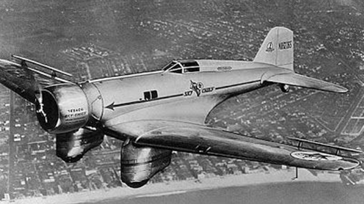 The Northrop Gamma was a single-engine all-metal monoplane cargo aircraft used in the 1930s. Towards the end of its service life, it was developed into the A-17 light bomber. The Gamma was a further development of the successful Northrop Alpha and shared its predecessor's aerodynamic innovations with wing fillets and multicellular stressed-skin wing construction. Like late Alphas, the fixed landing gear was covered in distinctive aerodynamic spats, and the aircraft introduced a fully enclosed cockpit. The Gamma saw fairly limited civilian service as mail planes with Trans World Airlines but had an illustrious career as a flying laboratory and record-breaking aircraft. The US military found the design sufficiently interesting to encourage Northrop to develop it into what eventually became the Northrop A-17 light attack aircraft. Military versions of the Gamma saw combat with Chinese and Spanish Republican air forces. Twenty Five Gamma 2Es were assembled in China from components provided by Northrop; these were deployed in various attack missions during the early stages of the Second Sino-Japanese War, particular against Imperial Japanese naval assets. In the morning of 11 November 1937, three Chinese Air Force Northrop 2ECs of the 2nd BG, 14th Squadron led by Capt. Yu attacked the IJN fleet aircraft carrier Kaga off the Ma'anshan Islands; the bombs fell wide into Kaga's wake, and the Chinese Gammas were pursued and intercepted by three A5Ms of Kaga's combat air patrol led by flight leader Jirō Chōno, shooting down two (Gammas no. 1405 of Sung I-Ching and Li Xi-Yong, and no. 1402 of Peng Te-Ming and Li Huan-Chieh) while Yu managed to escape into the clouds and return his damaged Gamma to base. On June 2, 1933 Frank Hawks flew his Gamma 2A "Sky Chief" from Los Angeles to New York in a record 13 hours, 26 minutes, and 15 seconds. In 1935, Howard Hughes improved on this time in his modified Gamma 2G making the west-east transcontinental run in 9 hours, 26 minutes, and 10 seconds. The most famous Gamma was the Polar Star. The aircraft was carried via ship and offloaded onto the pack ice in the Ross Sea during Lincoln Ellsworth's 1934 expedition to Antarctica. The Gamma was almost lost when the ice underneath it broke, and had to be returned to the United States for repairs. Polar Star's second assignment to Antarctica in September 1934 was also futile — a connecting rod broke and the aircraft had to be returned yet again for repairs. On January 3, 1935, Ellsworth and pilot Bernt Balchen finally flew over Antarctica. On November 23, 1935, Ellsworth and Canadian pilot Herbert Hollick-Kenyon attempted the world's first trans-Antarctic flight from Dundee Island in the Weddell Sea to Little America. The crew made four stops during their journey, in the process becoming the first people ever to visit Western Antarctica. During one stop, a blizzard completely packed the fuselage with snow which took a day to clear out. On December 5, after traveling over 2,400 miles (3,865 km) the aircraft ran out of fuel just 25 miles (40 km) short of the goal. The intrepid crew took six days to travel the remainder of the journey and stayed in the abandoned Richard E. Byrd camp until being found by the Discovery II research vessel on January 15, 1936. Polar Star was later recovered and donated to the Smithsonian National Air and Space Museum. For details of the 14 variants, click here. Specifications below are for the Gamma 2D variant. Gamma 2A Gamma 2E Gamma 2G Gamm 2J Northrop A-17 derivative3 points
 -
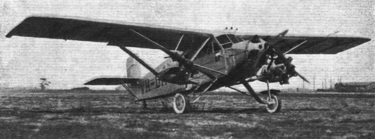 The Lasco Lascondor (also frequently known by the misspelling "Lasconder") was a 1930s Australian 8-seat passenger and mail carrier aircraft built by the Larkin Aircraft Supply Company (Lasco) at Coode Island, Victoria. It is claimed to be the first multi-engined aircraft designed and built in the Southern Hemisphere. Development of the Lascondor began in June 1928, concurrently with the company's Lascoter; the two aircraft had 90% commonality of structural parts. Like the Lascoter the Lascondor was a high-wing monoplane with a tubular steel structure, featuring a tailwheel undercarriage and a fully enclosed cabin for the passengers and the pilot. A major change was the Lascondor's three Armstrong Siddeley Mongoose engines instead of the Lascoter's single more powerful Siddeley Puma engine. The Lascondor also had greater fuel capacity and a slightly longer fuselage with a redesigned cabin to accommodate an extra row of seats. In addition, while the Lascoter had two sets of flying controls in the cockpit the Lascondor had only one to allow for another passenger seat, giving an overall capacity of seven passengers and one pilot. The only available photo of the Lascondor.2 points
 -
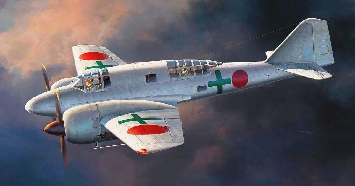 The Mitsubishi Ki-46 was a twin-engine reconnaissance aircraft that was used by the Imperial Japanese Army in World War II. Its Army Shiki designation was Type 100 Command Reconnaissance Aircraft (一〇〇式司令部偵察機); the Allied brevity code name was "Dinah". On 12 December 1937, the Imperial Japanese Army Air Force issued a specification to Mitsubishi for a long-range strategic reconnaissance aircraft to replace the Mitsubishi Ki-15. The specification demanded an endurance of six hours and sufficient speed to evade interception by any fighter in existence or development, but otherwise did not constrain the design by a team led by Tomio Kubo and Jojo Hattori. The resulting design was a twin-engined, low-winged monoplane with a retractable tailwheel undercarriage. It had a small diameter oval fuselage which accommodated a crew of two, with the pilot and observer situated in individual cockpits separated by a large fuel tank. Further fuel tanks were situated in the thin wings both inboard and outboard of the engines, giving a total fuel capacity of 1,490 L (328 imperial gallons). The engines, two Mitsubishi Ha-26s, were housed in close fitting cowlings developed by the Aeronautical Research Institute of the Tokyo Imperial University to reduce drag and improve pilot view. The first prototype aircraft, with the designation Ki-46, flew in November 1939 from the Mitsubishi factory at Kakamigahara, Gifu, north of Nagoya.[3] Tests showed that the Ki-46 was underpowered, and slower than required, only reaching 540 km/h (336 mph) rather than the specified 600 km/h (373 mph). Otherwise, the aircraft tests were successful. As the type was still faster than the Army's latest fighter, the Nakajima Ki-43, as well as the Navy's new A6M2, an initial production batch was ordered as the Army Type 100 Command Reconnaissance Plane Model 1 (Ki-41-I). To solve the performance problems, Mitsubishi fitted Ha-102 engines, which were Ha-26s fitted with a two-speed supercharger, while increasing fuel capacity and reducing empty weight. This version, designated Ki-46-II, first flew in March 1941. It met the speed requirements of the original specification, and was ordered into full-scale production, with deliveries starting in July. Although at first the Ki-46 proved almost immune from interception, the Imperial Japanese Army Air Force realised that improved Allied fighters such as the Supermarine Spitfire and P-38 Lightning could challenge this superiority, and in July 1942, it instructed Mitsubishi to produce a further improved version, the Ki-46-III. This had more powerful, fuel-injected Mitsubishi Ha-112 engines, and a redesigned nose, with a fuel tank ahead of the pilot and a new canopy, smoothly faired from the extreme nose of the aircraft, eliminating the "step" of the earlier versions. The single defensive machine gun of the earlier aircraft was omitted not long into the production run. The new version first flew in December 1942, demonstrating significantly higher speed 630 km/h (391 mph) at 6,000 m (19,700 ft). The performance of the Ki-46-III even proved superior to that of the aircraft intended to replace it (the Tachikawa Ki-70), which as a result did not enter production.[8] During operational testing in March 1944, it was discovered that replacing the engines' single exhaust collector ring with individual pipes provided extra thrust and an increase in top speed to 642 km/h (399 mph). In an attempt to yet further improve the altitude performance of the Ki-46, two prototypes were fitted with exhaust driven turbosupercharged Ha-112-II-Ru engines. This version first flew in February 1944, but only two prototypes were built. Mitsubishi factories made a total of 1,742 examples of all versions (34 x Ki-46-I, 1093 x Ki-46-II, 613 x Ki-46-III, 4 x Ki-46-IV) from 1941 to 1944. For details of operational history and 18 variants, click here.2 points
 -
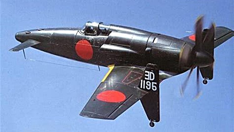 The Kyūshū J7W Shinden (震電, "Magnificent Lightning") is a World War II Japanese propeller-driven prototype fighter plane with wings at the rear of the fuselage, a nose-mounted canard, and a pusher engine. Developed by the Imperial Japanese Navy (IJN) as a short-range, land-based interceptor, the J7W was a response to Boeing B-29 Superfortress raids on the Japanese home islands. For interception missions, the J7W was to be armed with four forward-firing 30 mm type 5 cannons in the nose. The Shinden was expected to be a highly maneuverable interceptor, but only two prototypes were finished before the end of the war. A jet engine–powered version was considered, but never reached the drawing board. In the IJN designation system, "J" referred to land-based fighters and "W" to Watanabe Tekkōjo, the company that oversaw the initial design. The idea of a canard-based design originated with Lieutenant Commander Masayoshi Tsuruno, of the technical staff of the IJN in early 1943. Tsuruno believed the design could easily be retrofitted with a turbojet, when suitable engines became available. His ideas were worked out by the First Naval Air Technical Arsenal (Dai-Ichi Kaigun Koku Gijitsusho), which designed three gliders designated Yokosuka MXY6, featuring canards. These were built by Chigasaki Seizo K. K. and one was later fitted with a 22 hp Semi 11 (Ha-90) 4-cylinder air-cooled engine. The feasibility of the canard design was proven by both the powered and unpowered versions of the MXY6 by the end of 1943, and the Navy were so impressed by the flight testing, they instructed the Kyushu Aircraft Company to design a canard interceptor around Tsuruno's concept. Kyushu was chosen because both its design team and production facilities were relatively unburdened, and Tsuruno was chosen to lead a team from Dai-Ichi Kaigun Koku Gijitsusho to aid Kyushu's design works. The construction of the first two prototypes started in earnest by June 1944, stress calculations were finished by January 1945, and the first prototype was completed in April 1945. The 2,130 hp Mitsubishi MK9D (Ha-43) radial engine and its supercharger were installed behind the cockpit and drove a six-bladed propeller via an extension shaft. Engine cooling was to be provided by long, narrow, obliquely mounted intakes on the side of the fuselage. It was this configuration that caused cooling problems while running the engine while it was still on the ground. This, together with the unavailability of some equipment parts postponed the first flight of the Shinden. Even before the first prototype took to the air, the Navy ordered the J7W1 into production, with a quota of 30 Shinden a month given to Kyushu's Zasshonokuma factory and 120 from Nakajima's Handa plant. It was estimated some 1,086 Shinden could be produced between April 1946 and March 1947. On 3 August 1945, the prototype first flew, with Tsuruno at the controls, from Mushiroda Airfield. Two more short flights were made, a total of 45 minutes airborne, one each on the same days as the atomic bombings of Hiroshima and Nagasaki occurred, before the war's end. Flights were successful, but showed a marked torque pull to starboard (due to the powerful engine), some flutter of the propeller blades, and vibration in the extended drive shaft.2 points
 -
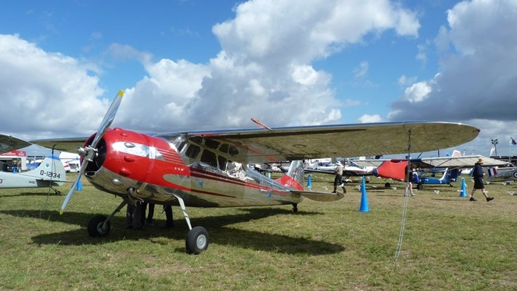 The Cessna 190 and 195 Businessliner are a family of light single radial engine powered, conventional landing gear equipped, general aviation aircraft which were manufactured by Cessna between 1947 and 1954. The 195 model was also used by the United States Air Force, United States Army, and Army National Guard as a light transport and utility aircraft under the designations LC-126/U-20. The Cessna 190 and 195 were Cessna's only postwar radial-engined aircraft. The first prototype flew in 1945, after the end of World War II and both the 190 and 195 entered production in 1947. The 195 was the first Cessna airplane to be completely constructed of aluminum and features a cantilever wing, similar to the pre-war Cessna 165 from which it is derived. The wing differs from later Cessna light aircraft in that it has a straight taper from root chord to tip chord and no dihedral. The airfoil employed is a NACA 2412, the same as used on the later Cessna 150, 172 and 182. The 190/195 fuselage is large in comparison to other Cessna models because the 42" diameter radial engine had to be accommodated in the nose. There are two rows of seats: two individual seats in the first row, with a comfortable space between them and up to three passengers can be accommodated on a bench seat in the second row. The 190/195 has flat sprung-steel landing gear legs derived from Cessna's purchase of the rights to Steve Wittman's Big X. Many have been equipped with swiveling crosswind landing gear which allows landing with up to 15 degrees of crab. While the crosswind gear simplifies the actual landing, it makes the aircraft difficult to handle on the ground. The 195 is equipped with a retractable step that extends when the cabin door is opened, although some have been modified to make the step a fixed unit. The aircraft was expensive to purchase and operate for private use and Cessna therefore marketed them mainly as a business aircraft under the name "Businessliner". The engines fitted to the 190 and 195 became well known for their oil consumption. The aircraft has a 5-US-gallon (19 L) oil tank, with 2 US gallons (7.6 L) the minimum for flight. Typical oil consumption with steel cylinder barrels is 2 US quarts (1.9 L) per hour. A factory-produced floatplane version was equipped with a triple tail for improved yaw stability. The Cessna 195 produces a cruise true airspeed of 148 knots (274 km/h) (170 MPH) on a fuel consumption of 16 US gallons (61 L) per hour. It can accommodate five people. Including the LC-126s, a total of 1180 190s and 195s were built. The 190 was originally introduced at a price of USD$12,750 in 1947 (equivalent to $173,978 in 2023). When production ended in 1954 the price had risen to USD$24,700 (equivalent to $280,239 in 2023) for the 195B. This compared to USD$3,495 for the Cessna 140 two seater of the same period. Variants The main difference between the 190 and the 195 models was the engine installed. 190 Powered by a Continental W670-23 engine of 240 hp (180 kW) and first certified on 1 July 1947. 195 (Specifications below) Powered by a Jacobs R-755A2 engine of 300 hp (225 kW) and first certified on 12 June 1947. 195A Powered by a Jacobs L-4MB (R-755-9) engine of 245 hp (184 kW) and first certified on 6 January 1950. 195B Powered by a Jacobs R-755B2 engine of 275 hp (206 kW) and first certified on 31 March 1952. It featured flaps increased in area by 50% over earlier models. LC-126A Military designation for the Cessna 195, five-seat communication aircraft for the US Army, it could be fitted with skis or floats, 15 built. LC-126B Similar aircraft to the LC-126 for Air National Guard use, five built. LC-126C Variant of the LC-126A for instrument training/liaison, 63 built. U-20B LC-126B redesignated by the USAF after 1962. U-20C LC-126C redesignated by the USAF after 1962.2 points
 -
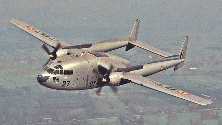 The Fairchild C-119 Flying Boxcar (Navy and Marine Corps designation R4Q) is an American military transport aircraft developed from the World War II-era Fairchild C-82 Packet, designed to carry cargo, personnel, litter patients, and mechanized equipment, and to drop cargo and troops by parachute. The first C-119 made its initial flight in November 1947, and by the time production ceased in 1955, 1,183 had been built. The Air Force C-119 and Navy R4Q was initially a redesign of the earlier C-82 Packet, built between 1945 and 1948. The Packet had provided limited service to the Air Force's Tactical Air Command and Military Air Transport Service before its design was found to have several serious problems. Though it continued in service until replaced, all of these were addressed in the C-119, which had its first test flight already in 1947. To improve pilot visibility, enlarge the cargo area, and streamline aerodynamics, the C-119 cockpit was moved forward to fit flush with the nose, rather than over the cargo compartment. The correspondingly longer fuselage resulted in more usable cargo space and larger loads than the C-82 could accommodate. The C-119 also got new engines, with 60% more power, four-bladed props to three, and a wider and stronger airframe. The first C-119 prototype (called the XC-82B) made its initial flight in November 1947, with deliveries of C-119Bs from Fairchild's Hagerstown, Maryland factory beginning in December 1949. In 1951, Henry J. Kaiser was awarded a contract to assemble additional C-119s at the Kaiser-Frazer automotive factory located in the former B-24 plant at Willow Run Airport in Belleville, Michigan. Initially, the Kaiser-built C-119F differed from the Fairchild aircraft by the use of Wright R-3350-85 Duplex Cyclone engines in place of Fairchild's use of the Pratt & Whitney R-4360 Wasp Major radial engine. Kaiser built 71 C-119s at Willow Run in 1952 and 1953 (AF Ser. No. 51-8098 to 51-8168) before converting the factory for a planned production of the Chase C-123 that never eventuated. The Kaiser sub-contract was frowned upon by Fairchild, and efforts were made through political channels to stop Kaiser's production, which may have proven successful. Following Kaiser's termination of C-119 production the contract for the C-123 was instead awarded to Fairchild. Most Kaiser-built aircraft were issued to the U.S. Marine Corps as R4Qs, with several later turned over to the South Vietnamese air force in the 1970s, a few others were later shipped to Belgium and Italy. The AC-119G Shadow gunship variant was fitted with four six-barrel 7.62 mm (0.300 in) NATO miniguns, armor plating, flare launchers, and night-capable infrared equipment. Like the AC-130 that replaced it, the AC-119 proved to be a potent weapon. The AC-119 was made more deadly by the introduction of the AC-119K Stinger version, which featured the addition of two General Electric M61 Vulcan 20 mm (0.79 in) cannon, improved avionics, and two underwing-mounted General Electric J85-GE-17 turbojet engines, adding nearly 6,000 lbf (27 kN) of thrust. Other major variants included the EC-119J, used for satellite tracking, and the YC-119H Skyvan prototype, with larger wings and tail. In civilian use, many C-119s feature the "Jet-Pack" modification, which incorporates a 3,400 lbf (15,000 N) Westinghouse J34 turbojet engine in a nacelle above the fuselage. For details of operational history and 21 variants, click here.2 points
 -
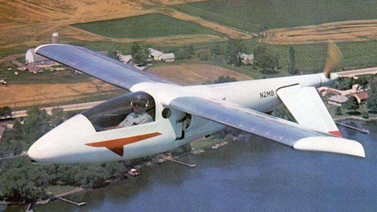 The Aerocar Mini-IMP (Independently Made Plane) is a light aircraft designed by Moulton Taylor and marketed for homebuilding by Aerocar International. It is a scaled-down derivative of his original Aerocar IMP design. A two-seat version called the Bullet was also built. The Mini-IMP follows the same unconventional layout as its larger predecessor, with a center mounted engine, long driveshaft to a tail propeller, and inverted-V rudder/elevators. The aircraft is available in the form of plans for amateur construction. Following Taylor's death, the plans and licensing for the Mini-IMP have been marketed by the Mini-IMP Aircraft Company of Weatherford, Texas. The aircraft features a cantilever high-wing, a single-seat enclosed cockpit, fixed or retractable tricycle landing gear or conventional landing gear and a single engine in pusher configuration. The aircraft is made from riveted aluminum sheet. Its 24.5 ft (7.5 m) span wing is mounted well behind the pilot and employs a NASA GA(PC)-1 airfoil. The engine is mounted behind the pilot's seat driving the propeller through an extension shaft. Engines used include the 60 to 100 hp (45 to 75 kW) Volkswagen air-cooled engine four-stroke. Taylor claimed the Mini-IMP was not an original design, but an updated version of the 1912 Edson Fessenden Gallaudet Bullet, a design that was capable of 110 mph in the earliest days of flight. In the late 1970s inquiries were made concerning a military version of the Mini-IMP, skinned with Kevlar, armed with two 7.62-millimeter machine guns, and with room in the baggage compartment for a considerable quantity of ammunition. Nothing came of the proposal.2 points
 -
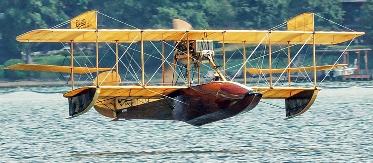 (No to be confused with the Curtiss SOC Seagull of WW2) The Curtiss Seagull was a civil variant of the Curtiss MF flying boat trainer produced from 1918, the civil aircraft having a 119 kw (160 hp) Curtiss C.6 six-cylinder in-line engine in place of the V-8 unit in the military variants. The MF was one of a long line of flying boats produced for the US services following the entry of the United States into World War I, when flying boats were required for patrolling coastal waters to prevent German submarine operations. Two examples of the Seagull came to Australia. Seagull G-AUCV (c/ n MF.419/28) was registered in 1921. It left Double Bay, Sydney, NSW on 13 March 1921 and made an epic flight to and from Tasmania, this being described as the First Aerial Reconnaissance in Australia, the pilot being Capt Andrew Lang(said to be shot down by the Red Baron during World War I, the operation being financed and promoted by Lebbeus Hordern. Cameras were carried on board in order that aerial photographs could be taken of the coastline. The auxiliary yacht ‘Acielle’ accompanied the expedition and acted as a tender for the Seagull. The flight was made in short stages, the first night being at the Shoalhaven River, near Nowra, NSW, thence to Jervis Bay, Moruya, down the coast to Eden and Marlo where the Victorian Premier, Mr Lawson, was met. Later he was taken for a flight over the area. Stops were made and local flights were made with passengers. From Welshpool it flew to Lady Barren and then across the Tasman, landing on the Tamar River close to Cataract Gorge. The return flight commenced on 19 June and the aircraft arrived at Double Bay on 4 July 1921. The bottom photo below shows the aircraft on the Tamar River. For more details of these aircraft click here.2 points
 -
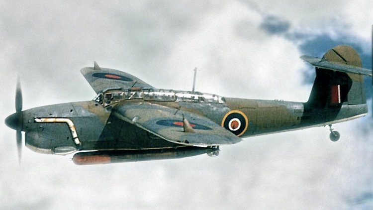 The Fairey Barracuda was a British carrier-borne torpedo and dive bomber designed by Fairey Aviation. It was the first aircraft of this type operated by the Royal Navy's Fleet Air Arm (FAA) to be fabricated entirely from metal. The Barracuda was developed as a replacement for the Fairey Albacore biplanes. Development was protracted due to the original powerplant intended for the type, the Rolls-Royce Exe, being cancelled. It was replaced by the less powerful Rolls-Royce Merlin engine. On 7 December 1940, the first Fairey prototype conducted its maiden flight. Early testing revealed it to be somewhat underpowered. However, the definitive Barracuda Mk II had a more powerful model of the Merlin engine, while later versions were powered by the larger and even more powerful Rolls-Royce Griffon engine. The type was ordered in bulk to equip the FAA. In addition to Fairey's own production line, Barracudas were also built by Blackburn Aircraft, Boulton Paul, and Westland Aircraft. The type participated in numerous carrier operations during the conflict, being deployed in the Atlantic Ocean, Mediterranean Sea, and the Pacific Ocean against the Germans, Italians, and Japanese respectively during the latter half of the war. One of the Barracuda's most noteworthy engagements was a large-scale attack upon the German battleship Tirpitz on 3 April 1944. In addition to the FAA, the Barracuda was also used by the Royal Air Force, the Royal Canadian Navy, the Dutch Naval Aviation Service and the French Air Force. After its withdrawal from service during the 1950s, no intact examples of the Barracuda were preserved despite its once-large numbers, although the Fleet Air Arm Museum has ambitions to assemble a full reproduction. a total of 2602 Barracudas were built. For details of development and operational history, click here. Variants Barracuda Two prototypes (serial numbers P1767 and P1770) based on the Fairey Type 100 design. Mk I First production version, Rolls-Royce Merlin 30 engine with 1,260 hp (940 kW), 30 built Mk II Upgraded Merlin 32 engine with 1,640 hp (1,225 kW), four-bladed propeller, ASV II radar, 1,688 built Mk III Anti-submarine warfare version of Mk II with ASV III radar in a blister under rear fuselage, 852 built Mk IV Mk II (number P9976) fitted with a Rolls-Royce Griffon engine with 1,850 hp (1,380 kW), first flight 11 November 1944, abandoned in favour of Fairey Spearfish. Mk V Griffon 37 engine with 2,020 hp (1,510 kW), payload increased to 2,000 lb (910 kg), ASH radar under the left wing, revised tailfin, 37 built.2 points
 -
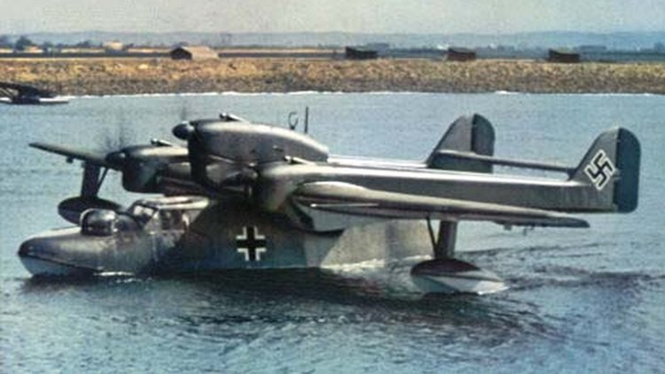 The Blohm & Voss BV 138 Seedrache (Sea Dragon), but nicknamed Der Fliegende Holzschuh ("flying clog", from the side-view shape of its fuselage, as well as a play on the title of the Wagner opera 'Der fliegende Holländer' or 'The Flying Dutchman') was a World War II German trimotor flying boat that served as the Luftwaffe's main seaborne long-range maritime patrol and naval reconnaissance aircraft. A total of 297 BV 138s were built between 1938 and 1943. Originally developed under the company name of Hamburger Flugzeugbau, the type was initially designated the Ha 138. Its appearance was unique in its combination of unusual design features with its twin boom tail unit, short fuselage and trimotor engine configuration. The short hull, with its hydrodynamic step beneath and flat sides, earned it the nickname, "Fliegender Holzschuh" (the flying clog). The booms of the twin tail unit, much like the smaller Focke-Wulf Fw 189 twin-engined reconnaissance monoplane, extended horizontally from the rear of the outer engine nacelles. For hydrodynamic reasons, the hull featured a distinct "turn-down", or "beak" at the stern. The first prototype featured a gull wing, but during the first flight it was discovered that this wing could not generate enough lift, so the concept was abandoned on the second prototype. The airplanes had also a hardpoint for catapult launches from seaplane tenders. Three piston engines were used. The central engine was mounted above the wing, while the wing engines were lower. The pre-production prototypes and the BV 138 A-01 to BV 138 A-06, were powered by various makes of engines ranging from 485 to 746 kW (650–1,000 hp). The first standardized version, BV 138 B-1, was powered by three 880 PS (868 hp, 647 kW) Junkers Jumo 205D two-stroke, opposed-piston aircraft diesel engines. The engine cowlings also had an atypical appearance, due to the unique nature of the vertical orientation of the six-cylinder opposed-piston Jumo 205 diesel engines, and resembled the cowlings of 4 or 6-cylinder inverted inline engines found on smaller civil and utility aircraft from the Jumo 205's propshaft placement, emerging forward at the uppermost front end of the powerplant. The choice for diesel engines made it possible to refuel at sea from U-boats, who also use diesel engines. When refuelling at sea, the airplane had to be fitted with a fuel filter as diesel fuel from ships contains some condensation. Originally developed under the company name of Hamburger Flugzeugbau, the type was initially designated the Ha 138. Its appearance was unique in its combination of unusual design features with its twin boom tail unit, short fuselage and trimotor engine configuration. The short hull, with its hydrodynamic step beneath and flat sides, earned it the nickname, "Fliegender Holzschuh" (the flying clog). The booms of the twin tail unit, much like the smaller Focke-Wulf Fw 189 twin-engined reconnaissance monoplane, extended horizontally from the rear of the outer engine nacelles. For hydrodynamic reasons, the hull featured a distinct "turn-down", or "beak" at the stern. The first prototype featured a gull wing, but during the first flight it was discovered that this wing could not generate enough lift, so the concept was abandoned on the second prototype. The airplanes had also a hardpoint for catapult launches from seaplane tenders. BV 138 being prepared for catapult launch on the aircraft tender Friesenland. Three piston engines were used. The central engine was mounted above the wing, while the wing engines were lower. The pre-production prototypes and the BV 138 A-01 to BV 138 A-06, were powered by various makes of engines ranging from 485 to 746 kW (650–1,000 hp). The first standardized version, BV 138 B-1, was powered by three 880 PS (868 hp, 647 kW) Junkers Jumo 205D two-stroke, opposed-piston aircraft diesel engines. The engine cowlings also had an atypical appearance, due to the unique nature of the vertical orientation of the six-cylinder opposed-piston Jumo 205 diesel engines, and resembled the cowlings of 4 or 6-cylinder inverted inline engines found on smaller civil and utility aircraft from the Jumo 205's propshaft placement, emerging forward at the uppermost front end of the powerplant. The choice for diesel engines made it possible to refuel at sea from U-boats, who also use diesel engines. When refuelling at sea, the airplane had to be fitted with a fuel filter as diesel fuel from ships contains some condensation. There were three gun positions on the aircraft: there was one on the bow with an enclosed, powered gun turret with a single MG 151/20 autocannon. On the stern the fields of fire were obstructed by the tail with the horizontal stabilizer, so there was one gun position lower on the fuselage and a second one higher just behind the central top engine. The gun position behind the central engine, which could see over the horizontal stabilizer, was a fully open Scarff ring-like emplacement which could mount a 7.92 mm MG 15 machine gun, but most aircraft mounted a 13 mm MG 131 heavy machine gun. The lower gun position at the rear fuselage sighted below the horizontal stabilizer. It too was left open and equipped with a machine gun on early aircraft, however later most aircraft mounted an enclosed powered turret similar to the one on the bow. For operational history and variants, click here.2 points
 -
 The Bellanca Aircruiser and Airbus were high-wing, single-engine aircraft built by Bellanca Aircraft Corporation of New Castle, Delaware. The aircraft was built as a "workhorse" intended for use as a passenger or cargo aircraft. It was available with wheels, floats or skis. The aircraft was powered by either a Wright Cyclone or Pratt and Whitney Hornet engine. The Airbus and Aircruiser served as both commercial and military transports. The first Bellanca Airbus was built in 1930 as the P-100. An efficient design, it was capable of carrying 12 to 14 passengers depending on the cabin interior configuration, with later versions carrying up to 15. In 1931, test pilot George Haldeman flew the P-100 a distance of 4,400 miles in a time aloft of 35 hours. Although efficient, with a cost per mile figure of eight cents per mile calculated for that flight, the first Airbus did not sell due to its water-cooled engine. The next model, the P-200 Airbus, was powered by a larger, more reliable air-cooled engine. One version (P-200-A) came with floats and operated as a ferry service in New York City, flying between Wall Street and the East River. Other versions included a P-200 Deluxe model, with custom interiors and seating for nine. The P-300 was designed to carry 15 passengers. The final model, the "Aircruiser," was the most efficient aircraft of its day, and would rank high amongst all aircraft designs. With a Wright Cyclone air-cooled supercharged radial engine rated at 715 hp, the Aircruiser could carry a useful load greater than its empty weight. In the mid-1930s, the Aircruiser could carry 4,000 lb payloads at a speed of between 145 and 155 mph, a performance that multi-engine Fokkers and Ford Trimotors could not come close to matching. In 1934, United States federal regulations prohibited single-engine transports on United States airlines, virtually eliminating future markets for the Aircruiser. Where the workhorse capabilities of the Aircruiser stood out was in Canada. Several of "The Flying Ws", as it was commonly dubbed in Canada, were used in northern mining operations, ferrying ore, supplies and the occasional passenger, into the 1970s. Variants Airbus Bellanca P Commercial version of Bellanca K, powered by a 500 hp (370 kW) Pratt & Whitney R-1860 Hornet.[2] P-100 Airbus 14-passenger monoplane powered by a 600 hp (450 kW) Curtiss Conqueror engine, one built, later converted into a P-200. P-200 Airbus 12-passenger monoplane, nine built and one converted from P-100. P-300 Airbus 15-seater monoplane powered by a Wright R-1820 Cyclone engine. Y1C-27 United States Army Air Corps designation for four P-200 Airbuses powered by 550 hp (410 kW) Pratt & Whitney R-1860 Hornet B engine. All later converted to C-27C. C-27A Airbus Production version of the Y1C-27 powered by a 650 hp (480 kW) Pratt & Whitney R-1860 Hornet B engine, ten built. One converted to a C-27B the rest converted to C-27Cs. C-27B Airbus One C-27A re-engined with a 675 hp (503 kW) Wright R-1820-17 Cyclone engine. C-27C Airbus Four Y1C-27s and nine of the C-27A re-engined with a 750 hp (560 kW) Wright R-1820-25 Cyclone engine. Aircruiser Aircruiser 66-67 Improved structure modified from a P-200 with a 675 hp (503 kW) Wright SR-1820 Cyclone engine Aircruiser 66-70 (Specifications below) An Aircruiser with a 710 hp (530 kW) Wright SGR-1820 Cyclone engine, five built - exported to Canada. Aircruiser 66-75 An Aircruiser with a 730 hp (540 kW) Wright Cyclone engine, three built. Aircruiser 66-76 A cargo-version of the Aircruiser with a 760 hp (570 kW) Wright Cyclone. Aircruiser 66-80 An Aircruiser with an 850 hp (630 kW) Wright Cyclone engine.2 points
 -
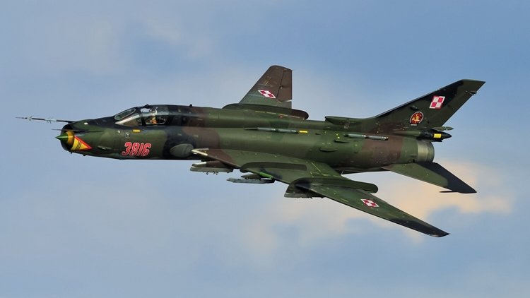 The Sukhoi Su-17 (izdeliye S-32) is a variable-sweep wing fighter-bomber developed for the Soviet military. Its NATO reporting name is "Fitter". Developed from the Sukhoi Su-7, the Su-17 was the first variable-sweep wing aircraft to enter Soviet service and was featured updated avionics. The aircraft also has variants which were designed to be exported to non-Soviet states such as the Sukhoi Su-22 and the less popular Su-20. It was produced from 1967-1990. The Su-17/20/22 series had a long career and has been operated by many air forces, including those of the Russian Federation, former Soviet republics, former Warsaw Pact, countries in the Arab world, Angola, and Peru. The Russian Federation retired its fleet in 1998. Although the Su-17 was capable of carrying nuclear weapons, it was used in roles ranging from close-air support to ground attack. Shortly after the Su-7 fighter-bomber was put into service, the Sukhoi Design Bureau was ordered to develop a modernization program. The program would be aimed primarily at updating on-board avionics and takeoff/landing characteristics. The concept of variable-geometry wings - something gaining wider attention at that time - was adopted. The program was to be led by Sukhoi's head designer, Nikolay Zyrin. In 1963 the Sukhoi OKB with input from TsAGI created a variable-sweep wing technology demonstrator. The S-22I (also known as the Su-7IG, NATO designation "Fitter-B"), converted from a production Su-7BM, had fixed inner portions of the wing with movable outer segments that could be swept to 28°, 45°, or 62°. The S-22I first took off (with Vladimir Ilyushin at the controls) on 2 August 1966. It was later demonstrated at the air parade in Domodedovo in July 1967. Flight testing revealed that the configuration improved both take-off/landing characteristics, range and endurance. Handling was generally better than the fixed wing Su-7, with the exception that buffeting at high angles of attack to warn of imminent stall no longer occurred. For further details of the deveopment, operational history and variants of the series, click here. The photos on this page feature the Su-22 of the Polish Air Force, and the specifications below are for the Su-17M4.2 points
 -
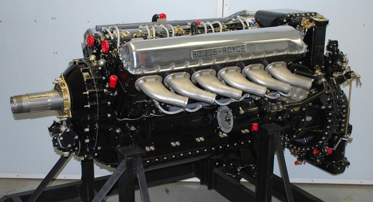 The Rolls Royce Merlin was the beating heart of any number of WWII military aircraft - and would you believe that it powered the Cromwell Cruiser tank? This link is to a lecture given by one of the developers of teh Merlin engine to de Haviland technical people in late 1945. I post it here in order to preserve it. http://www.wwiiaircraftperformance.org/merlin-lovesey.pdf The Rolls Royce Merlin fitted in a Spitfire Just some of the aircraft powered by Rolls Royce Merlin engines. Avro Lancaster Hawker Hurricane Supermarine Spitfire CAC CA-18 Mustang2 points
 -
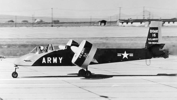 The Doak VZ-4 (or Doak Model 16) was an American prototype Vertical Takeoff and Landing (VTOL) aircraft built in the 1950s for service in the United States Army. Only a single prototype was built, and the U.S. Army withdrew it from active trials in 1963. Edmund R. Doak, Jr., a self-taught engineer and vice president of Douglas Aircraft Company, founded Doak Aircraft Company in Torrance, California, in 1940. The company grew to 4,000 employees during World War II, with subcontracts from every major American aircraft manufacturer. These included molded plywood fuselages for trainers such as the AT-6 and Vultee BT-13, and doors, hatches and gun turrets for a multitude of aircraft. Doak proposed a VTOL aircraft to the U.S. Army's Army Transportation and Research and Engineering Command at Fort Eustis in Newport News, Virginia, in 1950. He touted the aircraft as able to take off and land in a small area, hover and loiter over a target area, and fly backwards like a helicopter without the noise and vibration of a helicopter, while also having the horizontal cruising ability, high speed, wing-mounted weapons, and mission flexibility of a conventional fixed-wing fighter aircraft. Knowing that a Soviet attack on airbases would interdict takeoffs and landings by conventional aircraft, the Army found Doak's proposal attractive, and on 10 April 1956, it awarded Doak a contract to produce a single prototype for use as a research aircraft. The aircraft, designated the Doak Model 16 by the Doak company and assigned the serial number 56-9642, was originally powered by an 840 shp (630 kW) Lycoming YT53 turboprop engine mounted in the fuselage, later replaced by a 1,000 shp (750 kW) Lycoming T53-L-1 turbine. The engine drove two wingtip-mounted fiberglass tilting ducted fan propellers through a "T" box on the engine that transmitted power to the propellers via a 4-inch (102-mm) aluminum tubular shaft and two smaller shafts. Each propeller was 48-inch (1.22-meter) in diameter and the duct outer diameter was 60-inches (1.52-meter)). The fans were positioned vertically for takeoff and landing – with a rotation speed of 4,800 rpm required for liftoff – and rotated to a horizontal orientation for horizontal flight, the first time this VTOL propulsion concept was tested successfully. The aircraft had metal wings and a metal tail. To save weight, the aircraft originally was constructed of uncovered welded steel tubing, but after it was found that the open frame interfered with forward-speed tests, molded fiberglass was installed over its nose section and thin aluminum sheeting over its aft fuselage. It accommodated a two-person crew, with a pilot and observer seated in tandem in the cockpit. The pilot used a standard stick and rudder to control the aircraft. Its landing gear were taken from a Cessna 182 Skylane, its seats from a North American P-51 Mustang, and its duct actuators from a Lockheed T-33 Shooting Star. Flight testing began at Torrance Municipal Airport, and Doak completed several tests by 1958. The Model 16 hovered for the first time on 25 February 1958, and the first transition from vertical to horizontal flight (and back again) took place on 5 May 1958. Although the prototype generally was successful, its short takeoff and landing performance was less than hoped for and it displayed a tendency to nose up while making the transition from vertical to horizontal flight. Doak's engineers believed that they could solve the prototype's problems, and after taxiing testing, 32 hours of flight testing in a test stand, and 18 hours of tethered hovering, the aircraft was transferred to Edwards Air Force Base, California, in October 1958. It underwent another 50 hours of testing, in which it proved capable with the turbine engine of achieving a maximum speed of 230 mph (370 km.hr), a cruise speed of 175 mph (282 km/hr), a range of 250 miles (403 km), an endurance of one hours, and a service ceiling of 12,000 feet (3,658 meters).2 points
 -
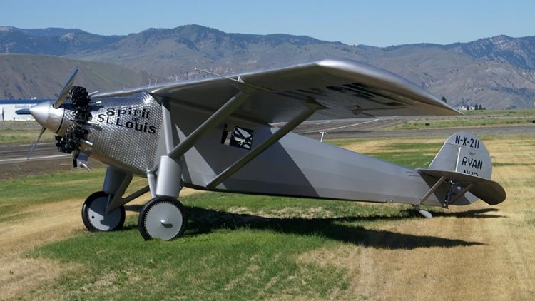 The Spirit of St. Louis (formally the Ryan NYP, registration: N-X-211) is the custom-built, single-engine, single-seat, high-wing monoplane that was flown by Charles Lindbergh on May 20–21, 1927, on the first solo nonstop transatlantic flight from Long Island, New York, to Paris, France, for which Lindbergh won the $25,000 Orteig Prize. Lindbergh took off in the Spirit from Roosevelt Airfield, Garden City, New York, and landed 33 hours, 30 minutes later at Aéroport Le Bourget in Paris, France, a distance of approximately 3,600 miles (5,800 km). One of the best-known aircraft in the world, the Spirit was built by Ryan Airlines in San Diego, California, owned and operated at the time by Benjamin Franklin Mahoney, who had purchased it from its founder, T. Claude Ryan, in 1926. The Spirit is on permanent display in the main entryway's Milestones of Flight gallery at the Smithsonian Institution's National Air and Space Museum in Washington, D.C. Officially known as the "Ryan NYP" (for New York to Paris), the single-engine monoplane was designed by Donald A. Hall of Ryan Airlines and named the "Spirit of St. Louis" in honor of Lindbergh's supporters from the St. Louis Raquette Club in his then hometown of St. Louis, Missouri. To save design time, the NYP was loosely based on the company's 1926 Ryan M-2 mailplane, the main difference being the NYP's 4,000-mile (6,400 km) range. As a nonstandard design, the government assigned it the registration number N-X-211 (for "experimental"). Hall documented his design in "Engineering Data on the Spirit of St. Louis", which he prepared for the National Advisory Committee for Aeronautics (NACA) and is included as an appendix to Lindbergh's 1953 Pulitzer Prize winning book The Spirit of St. Louis. B.F. "Frank" Mahoney and Claude Ryan had co-founded the company as an airline in 1925 and Ryan remained with the company after Mahoney bought out his interest in 1926, although there is some dispute as to how involved Ryan may have been in its management after selling his share. It is known, however, that Hawley Bowlus was the factory manager who oversaw construction of the Ryan NYP, and that Mahoney was the sole owner at the time of Donald A. Hall's hiring. The Spirit was designed and built in San Diego to compete for the $25,000 Orteig Prize for the first nonstop flight between New York and Paris. Hall and Ryan Airlines staff worked closely with Lindbergh to design and build the Spirit in just 60 days. Although what was actually paid to Ryan Airlines for the project is not clear, Mahoney agreed to build the plane for $6,000 and said that there would be no profit; he offered an engine, instruments, etc. at cost. After first approaching several major aircraft manufacturers without success, in early February 1927 Lindbergh, who as a U.S. Air Mail pilot was familiar with the good record of the M-1 with Pacific Air Transport, wired, "Can you construct Whirlwind engine plane capable flying nonstop between New York and Paris ...?" Mahoney was away from the factory, but Ryan answered, "Can build plane similar M-1 but larger wings... delivery about three months." Lindbergh wired back that due to competition, delivery in less than three months was essential. Many years later, John Vanderlinde, chief mechanic of Ryan Airlines, recalled, "But nothing fazed B.F. Mahoney, the young sportsman who had just bought Ryan." Mahoney telegraphed Lindbergh back the same day: "Can complete in two months." Lindbergh was convinced: "I believe in Hall's ability; I like Mahoney's enthusiasm. I have confidence in the character of the workmen I've met."[citation needed] He then went to the airfield to familiarize himself with a Ryan aircraft, either an M-1 or an M-2, then telegraphed his St. Louis backers and recommended the deal, which was quickly approved. Mahoney lived up to his commitment. Working exclusively on the aircraft and closely with Lindbergh, the staff completed the Spirit of St. Louis 60 days after Lindbergh arrived in San Diego. Powered by a Wright Whirlwind J-5C 223-hp radial engine, it had a 14 m (46-foot) wingspan, 3 m (10 ft) longer than the M-1, to accommodate the heavy load of 1,610 L (425 gal) of fuel. In his 1927 book We, Lindbergh acknowledged the builders' achievement with a photograph captioned "The Men Who Made the Plane", identifying: "B. Franklin Mahoney, president, Ryan Airlines", Bowlus, Hall and Edwards standing with the aviator in front of the completed aircraft. Lindbergh believed that multiple engines resulted in a greater risk of failure while a single-engine design would give him greater range. To increase fuel efficiency, the Spirit of St. Louis was also one of the most advanced and aerodynamically streamlined designs of its era. Lindbergh believed that a flight made in a single-seat monoplane designed around the dependable Wright J-5 Whirlwind radial engine provided the best chance of success. The Ryan NYP had a total fuel capacity of 450 U.S. gallons (1,700 L; 370 imp gal) or 2,710 pounds (1,230 kg) of gasoline, which was necessary in order to have the range to make the anticipated flight non-stop. The fuel was stored in five fuel tanks, a forward tank – 88 U.S. gal (330 L; 73 imp gal), the main – 209 U.S. gal (790 L; 174 imp gal), and three wing tanks – total of 153 U.S. gal (580 L; 127 imp gal).[5] Lindbergh modified the design of the plane's "trombone struts" attached to the landing gear to provide a wider wheelbase in order to accommodate the weight of the fuel. At Lindbergh's request, the large main and forward fuel tanks were placed in the forward section of the fuselage, in front of the pilot, with the oil tank acting as a firewall. This arrangement improved the center of gravity and reduced the risk of the pilot being crushed to death between the main tank and the engine in the event of a crash. This design decision meant that there could be no front windshield, and that forward visibility would be limited to the side windows. This did not concern Lindbergh as he was accustomed to flying in the rear cockpit of mail planes with mail bags in the front. When he wanted to see forward, he would slightly yaw the aircraft and look out the side. To provide some forward vision as a precaution against hitting ship masts, trees, or structures while flying at low altitude, a Ryan employee who had served in the submarine service installed a periscope which Lindbergh helped design. It is unclear whether the periscope was used during the flight. The instrument panel housed fuel pressure, oil pressure and temperature gauges, a clock, altimeter, tachometer, airspeed indicator, bank and turn indicator, and a liquid magnetic compass. The main compass was mounted behind Lindbergh in the cockpit, and he read it using the mirror from a women's makeup case which was mounted to the ceiling using chewing gum. Lindbergh also installed a newly developed Earth Inductor Compass made by the Pioneer Instrument Company which allowed him to more accurately navigate while taking account of the magnetic declination of the earth. Lindbergh's ultimate arrival in Ireland deviated from his flight plan by just a few miles. Lindbergh sat in a cramped cockpit which was 94 cm wide, 81 cm long and 130 cm high (36 in × 32 in × 51 in). The cockpit was so small, Lindbergh could not stretch his legs. The Spirit of St. Louis was powered by a 223 hp (166 kW), air-cooled, nine-cylinder Wright J-5C Whirlwind radial engine. The engine was rated for a maximum operating time of 9,000 hours (more than one year if operated continuously) and had a special mechanism that could keep it clean for the entire New York-to-Paris flight. It was also, for its day, very fuel-efficient, enabling longer flights carrying less fuel weight for given distances. Another key feature of the Whirlwind radial engine was that it was rated to self-lubricate the engine's valves for 40 hours continuously. Lubricating, or "greasing," the moving external engine parts was a necessity most aeronautical engines of the day required, to be done manually by the pilot or ground crew prior to every flight and would have been otherwise required somehow to be done during the long flight. The engine was built at Wright Aeronautical in Paterson, New Jersey by a 24-year-old engine builder, Tom Rutledge, who was disappointed that he was assigned to the unknown aviator, Lindbergh. Four days after the flight, he received a letter of congratulations from the Wright management. For more information, click here.2 points
 -
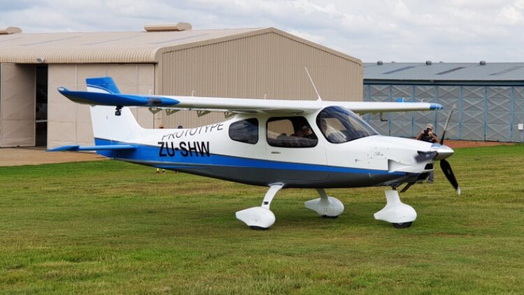 The most anticipated version of the phenomenally successful Sling series is the Sling High Wing. The High Wing – or just Sling HW – was first proposed as a high wing version of the Sling 2 at the same time as founder Mike Blyth started work on the original Sling 2 back in 2005. The final product has come a long way from the early Sling 2s. The Sling TSi is unique in that it is the only aircraft that comes in almost identical low wing and high wing versions. For this reason the comparison with the low wing Sling TSI is particularly interesting. The rationale for developing both a low wing and a high wing are many. Mike Blyth provides the following reasons: “The engine–airframe combination of the Sling TSi is so perfect that to fail to exploit it in a high wing model would feel like a crime. Also, there’s a real gap in the market as there is no other aircraft in that space. And you can see really well out of a high wing when flying straight, and it can be a great camera and/ or surveillance platform.” The Sling HW made its first flight as promised before the end of 2020. That development and construction had continued through the Covid lockdown is testimony to the dedication and commitment the Sling team brought to the project. A readily noticeable difference between the Low Wing and High is that the high has a vertical fin and rudder a full 20 cm longer than the Low Wing. Given the High Wing ‘nosedraggers’ high stance, this may make getting the tail under a low hangar door opening something to watch. The Sling HW and TSi are immediately distinguishable by the large NACA duct on the right side of the cowl which feeds air into the engine’s high-volume intercooler. Sling Aircraft has done a great job integrating this duct into the Sling’s distinctive shark nose cowling. For the full write-up from which these notes were extracted click here.2 points
 -
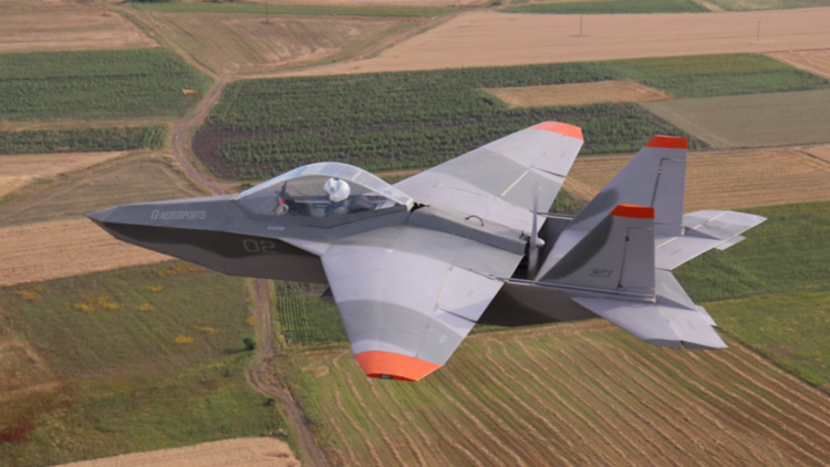 Archon SF-1 is an evolutionary unique aircraft, that utilizes the look of a modern fighter aircraft but lies into the Ultalight(EU)/LSA(USA) category. The idea behind the design is an affordable recreational aircraft that offers the impression and the feeling of a fighter aircraft. It was designed and built in Greece, by George Iliopoulos. The maiden flight was made in July, 2009. Since then, it’s been being test flown in regular basis and have received minor changes to improve the overall flight qualities. The standard engine mount is for the Rotax 503, 532, 582 engines.Alluminum alloy construction, light-weight and durable material, corrosion resistant, UV protected. Easy to work with.Basic skills and tools required to assemble in a small workshop.2 points
 -
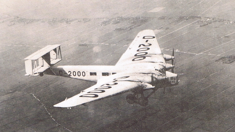 The Junkers G.38 was a large German four-engined transport aircraft which first flew in 1929. Two examples were constructed in Germany. Both aircraft flew as a commercial transport within Europe in the years leading up to World War II. During the 1930s, the design was licensed to Mitsubishi, which constructed and flew a total of six aircraft, in a military bomber/transport configuration, designated Ki-20. The G.38 carried a crew of seven. Onboard mechanics were able to service the engines in flight due to the G.38's blended wing design, which provided access to all four power plants. During the 1920s, Hugo Junkers made several attempts to produce a large scale commercial transport. His initial attempt, the four-engined JG1, was developed during 1921-1922; but Junkers was forced to destroy the incomplete airplane based on post-WWI Allied demands citing the Treaty of Versailles. Later in the decade, in 1925, he published design specifications for a proposed eighty passenger trans-Atlantic aircraft - the J.1000 project. Then again, towards the end of the decade, the G.40 project was started by the Junkers design team as a trans-Atlantic mail plane. From the G.40 design, which was a seaplane configuration, Junkers also developed a landplane design, designated the G.38. Despite interest from the German armed forces in the G.40 variant, Junkers pushed forward with the landplane design which, having received financing from the Reich Air Ministry (Reichsluftfahrtministerium), was taken forward to the construction stage. The first Junkers prototype—3301 and marked as D-2000—first flew on 6 November 1929 with four diesel engines: two Junkers L55 V-12 engines and two 294 kW L8 inline-6 engines, with a total power rating of 1470 kW (1971 hp). The Reich Air Ministry purchased the D-2000 for demonstration flights, and took delivery on 27 March 1930. In flight tests, the G.38 set four world records including speed, distance and duration for airplanes lifting a 5000 kg payload. On 2 May 1930 Luft Hansa put the D-2000 into commercial service for both scheduled and chartered flights. Structurally the G.38 conformed to standard Junkers' practice, with a multi-tubular spar cantilever wing covered (like the rest of the aircraft) in stressed, corrugated duraluminium. The biplane tail, found in other large aircraft of the time, was intended to reduce rudder forces; initially there were three rudders with only a central fixed fin. The undercarriage was fixed, with double tandem main wheels that were initially enclosed in very large spats. The wing had the usual Junkers "double wing" form, the name referring to the full span movable flaps which served also as ailerons in the outer part. On 2 February 1931 the Leipzig-based Junkers' yard re-engined the D-2000 with two Junkers L8 and two L88 engines, giving a total power rating of 1764 kW (2366 hp) and increasing passenger capacity from 13 to 19. During its early life the G.38 was the largest landplane in the world. Passenger accommodation was sumptuous by today's standards and was meant to rival that found on the competing Zeppelin service offered by DELAG. The plane was unique in that passengers were seated in the wings, which were 1.7 m (5 ft 7 in) thick at the root. There were also two seats in the extreme nose. The leading edge of each wing was fitted with sloping windscreens giving these passengers the forward-facing view usually available only to pilots. There were three 11-seat cabins, plus smoking cabins and washrooms. In design terms the G-38 followed the Blended Wing Body design pioneered by Louis de Monge, later followed by Vincent Burnelli in his UB14 and later CBY-3 designs, and even later considered by both NASA and Boeing as an alternative to traditional tube and wing aircraft configurations. For operational history, click here.2 points
 -
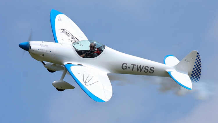 The Silence Twister is a German ultralight designed by Silence Aircraft for amateur construction, either from plans or kits. The prototype first flew on 30 September 2000. The Twister is a single-seat low-wing monoplane with elliptical wings and tailplane. It has a retractable conventional landing gear with a fixed tailwheel. The design drew inspiration from the Supermarine Spitfire, and the shapes of the Twister's wings, fin and tailplane all recall the famous World War II fighter. Designed to take engines up to 94 hp (70 kW), the prototype was fitted with a 53.6 hp (40 kW) single-rotor MidWest Wankel engine. This compact rotary motor allowed a sleek engine cowling, but the engine was rejected and production aircraft use 85 hp (63 kW) Jabiru 2200 or 95 hp (71 kW) ULPower UL260i engines. An electric aircraft version was under development in 2010. The Twister prototype was fitted with Silence Aircraft's own automatic variable-pitch propeller called the "VProp". The LAA have yet to allow the VProp to be fitted on UK aircraft, so UK Twisters have fixed-blade propellers instead. Twenty-one examples had been completed and flown by December 2011. Variants SA155 Initial prototype powered by a 34 kW (45 hp) MidWest AE50 Wankel rotary engine. The second prototype was powered by a 34 kW (45 hp) Diamond AE50 engine.[2] SA180 powered by a 60 kW (80 hp) Jabiru 2200 engine.[2] Akron A version developed for the US market under Experimental aircraft certification rules.2 points
 -
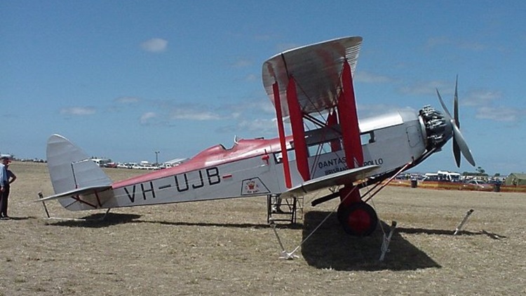 Following the success of the de Havilland DH.50J in Australia, the company was asked to design a larger replacement using a Bristol Jupiter engine. The cabin had room for six to eight passengers with the pilot in an open cockpit behind the wings. The aircraft took only 10 weeks to design and the prototype first flew in December 1927. Following test flights in England, the aircraft was sent to de Havilland Australia in Melbourne. After reassembly, the prototype first flew on 2 March 1928 and was used on scheduled services between Adelaide and Broken Hill by MacRobertson Miller Aviation. The prototype was originally called Canberra which was used as a type name until it was changed to Giant Moth. A total of 10 aircraft were built, including one in Canada built from components with the rest coming from the Stag Lane production line. Three aircraft for Canada (G-CAPG), (G-CARD) and (G-CAJT) were fitted with Short Brothers floats at Rochester before one was delivered to Canadian Vickers. Three aircraft were used in Australia on air mail services by Australian Aerial Services Ltd and QANTAS. The two QANTAS Giant Moths, Apollo (G-AUJB) and Diana (G-AUJC), were acquired in April and May 1929 respectively. They were the first QANTAS aircraft equipped with toilets. The airline took them out of service in 1935 because the Bristol Jupiter XI engines were unreliable. Apollo was sold that year and crashed near Mubo, New Guinea, on 9 May 1938. Another aircraft, Geraldine (G-AAAN), was bought by the Daily Mail to carry a photographer and his motorcycle around the United Kingdom. For more information, click here.2 points
 -
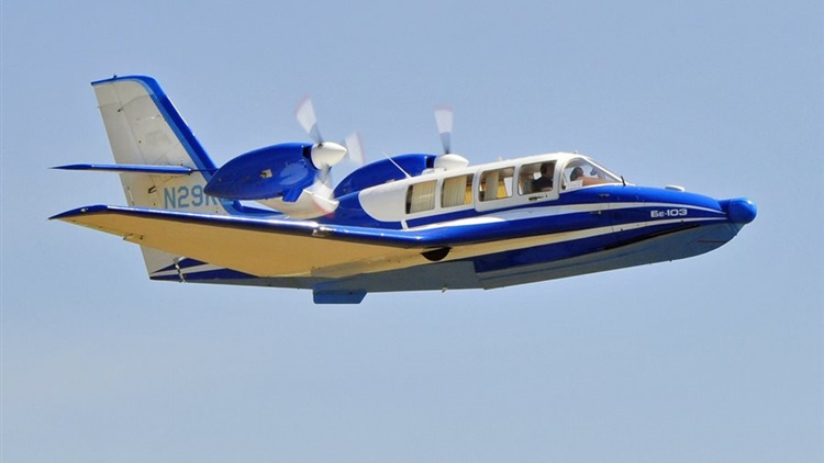 Intended for autonomous operation in the unmarked areas of Russia's far north and Siberia, the Be-103 was designed for short-haul routes in regions that have rivers, lakes and streams, but are otherwise inaccessible. The Be-103 is a mid-wing monoplane, making use of the modified wing roots as water-displacing sponsons. It features an all-moving slab tail and retractable tricycle landing gear for land operations. Its hallmark and most distinguishing design feature is the water-displacing wing, an unusual feature for a seaplane, with three aquaplaning implements (planing step, port and starboard wing trailing edges) which substantially enhance the aircraft's on-the-water stability and seaworthiness. The Be-103 features include an advanced, blended wing, swept at 22°, with 11-foot (3.4 m)-long fixed leading edge slats, trailing-link main landing gear, and three-bladed MT-12 reverse pitch propellers. Fuel is stored in the wet wings. The aircraft is built from aluminum-lithium alloy with titanium used in high-stress areas. A 30-parameter, five-hour flight data recorder, engine fire-detection systems and an ice detector are also standard, as are hydraulic brakes. However, unlike most modern aircraft, the Be-103 is not equipped with wing flaps. When flying solo, ballast must be placed near the right front seat due to center of gravity issues. As of 2010, three aircraft were on the United States civil register. In 2004 China signed a US$20mil contract with KnAAPO for the delivery of 20 aircraft. In 2016 contract was signed between Taganrog-based Beriev Aircraft Company and the Chinese Energy Leader Aircraft Manufacturing to start licensed production of Beriev Be-103 in China. Variants Be-103 Twin-engine light utility amphibian aircraft, seating one pilot and five passengers. SA-20P Eight-seat version powered by single VOKEM M14X radial engine; one prototype.2 points
 -
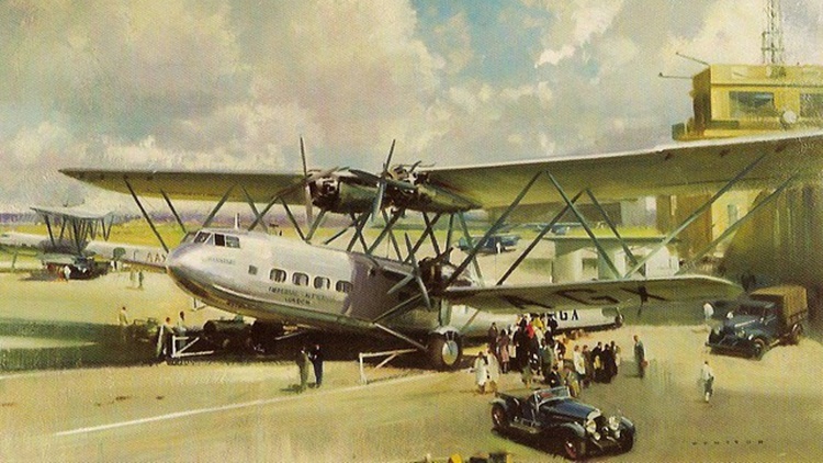 They held the distinction of being the largest airliners in regular use in the world upon the type's introduction in 1931. The H.P.42/45 were designed in response to a specification issued during 1928 by British airline Imperial Airways; the two models share considerable similarities, the H.P.42 being optimised towards greater range at the expense of payload while the H.P.45 had these priorities inverted, allowing the latter to carry more passengers over shorter distances. Imperial Airways approved of Handley Page's proposals and ordered four aircraft of the two variants to serve as the new land-based long-distance flagships of its fleet. On 14 November 1930, the prototype, named Hannibal, conducted its maiden flight. Following their introduction into Imperial Airways, they formed the backbone of the airliner's land-based fleet through most of the 1930s and, along with the company's numerous flying boats, have been considered to be icons of their era. A total of eight aircraft were built, four of each type; all were named, with names beginning with the letter "H". Three of the survivors were pressed into Royal Air Force (RAF) service at the outbreak of the Second World War. By the end of 1940, all of the aircraft had been destroyed as a result of several accidents. In total, four H.P.42 and four H.P.45 aircraft were delivered, but two of the HP45s were later converted into HP42s. The H.P.45 carried more passengers with a reduced range and baggage capacity, and was intended for Imperial Airways' European routes. For details of the development, design, operational history and individual histories of each of the eight aircraft, click here. The specifications below are for the H.P.42 variant.2 points
 -
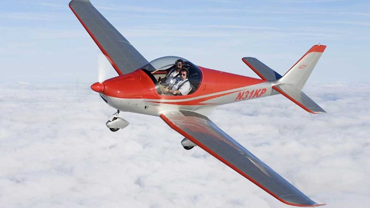 It is a conventional low-wing monoplane featuring all-metal construction and tricycle undercarriage. Jilhavan Aircraft built the Kappa Sova for Kappa 77 from 1997 to 2004 and obtained marketing rights in 2005 when Kappa became insolvent. They became a subsidiary of Skyleader Aircraft in 2008 when the type was redesignated Jihlavan Skyleader. It is an all-metal design apart from a carbon fibre cockpit frame. It has two-spar tapered wings with 6° of dihedral, electrically operated Fowler flaps and upturned Küchemann tips. The fin and rudder are swept. The straight tapered tailplane is set on top of the fuselage, the port elevator carrying a trim tab. The original Sova/Skyleader 150 has staggered side-by-side configuration seating with the starboard seat 200 mm (8 in) aft of the other, but a widened fuselage allows the Skyleader 200 to have true side-by-side seating. The earlier version has a forward-hinged canopy with fixed rear transparencies; the Skyleader 200 has a single-piece canopy. Both these variants normally have an electrically actuated tricycle undercarriage with a steerable nosewheel, though a fixed version is an option and is standard on the later Skyleader 500 and 600 variants. For more details of the development and design, operational history and variants, click here. Specifications below are for the KP-2U Sova variant.2 points
 -
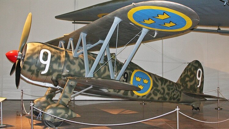 The Fiat CR.42 Falco (Falcon, plural: Falchi) is a single-seat sesquiplane fighter developed and produced by Italian aircraft manufacturer Fiat Aviazione. It served primarily in the Italian Regia Aeronautica in the 1930s and during the Second World War. The CR.42 was a development of Fiat’s earlier CR.32 fighter, powered by the more powerful supercharged Fiat A.74R1C.38 air-cooled radial engine and with improvements. It proved to be relatively agile in flight, attributed to its very low wing loading and a sometimes decisive tactical advantage. RAF Intelligence praised its exceptional manoeuvrability, further noting that "the plane was immensely strong", though it was technically outclassed by faster, more heavily armed monoplanes. While primarily used as a fighter, variants such as the CR.42CN night-fighter model, the CR.42AS ground-attack aircraft, and the CR.42B Biposto twin-seat trainer aircraft had other roles. During May 1939, the CR.42 entered service with the Regia Aeronautica; it was the last of the Fiat biplane fighters to enter front line service. By 10 June 1940, when Italy entered the Second World War, roughly 300 had been delivered; these defended metropolitan areas and important military installations at first. By the end of 1940, the Falco had been involved in combat on various fronts, including the Battle of France, the Battle of Britain, Malta, North Africa, and Greece. By the end of the war, Italian CR.42s had been used on further fronts, including Iraq, the Eastern Front and the Italian mainland. Following the signing of the Italian armistice with the Allies on 8 September 1943, the type was relegated to use as a trainer by the Italian Co-Belligerent Air Force, while some Italian CR.42s were seized by the Germans and used by the Luftwaffe for ground-attack operations. The CR.42 was produced and entered service in smaller numbers with the air forces of other nations, including Belgium, Sweden and Hungary. By the end of production, in excess of 1,800 CR.42s had been constructed, making it the most numerous Italian aircraft to be used during the Second World War. It has been claimed that the fighter had performed at its best during its service with the Hungarian Air Force, specifically during its deployment against Soviet forces on the Eastern Front of the war, where it reportedly achieved a kill to loss ratio of 12 to 1. Number built 1,817–1,819; First flight 23 May 1938; Retired 1948 For more details of development, design, operational history and 13 variants, click here.1 point
 -
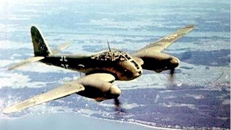 The Messerschmitt Me 410 Hornisse (Hornet) is a heavy fighter and Schnellbomber ("Fast Bomber" in English) designed and produced by the German aircraft manufacturer Messerschmitt. It was flown by the Luftwaffe during the latter half of the Second World War. Work began on producing a successor to the Bf 110 in 1937, however, the resulting Me 210 proved to be unsatisfactory, leading to production being halted in April 1942. Various options were considered, including the ambitious Me 310 derivative. Officials favoured an incremental improvement which was represented by the Me 410. Although visually similar to the preceding Me 210, and was sharing sufficient design similarities that incomplete Me 210s could be converted into Me 410s, there were key differences between the two aircraft. Chiefly, the Me 410 was powered by larger Daimler-Benz DB 603 engines, had a lengthened fuselage, and automatic leading edge slats. During late 1942, the Reichsluftfahrtministerium (RLM) were sufficiently convinced by the programme to proceed with quantity production of the type, the first Me 410s being delivered during January 1943. Various models were produced, including the Me 410A-1 light bomber, the A-1/U1 aerial reconnaissance aircraft, the A-1/U2 bomber destroyer, and the A-2/U4 night fighter. Upon their entry to service, the type was promptly flown on night time bombing missions in the British Isles, where the night fighters of the Royal Air Force (RAF) typically struggled to intercept it.[2] The Me 410 was also used as a bomber destroyer against the daylight bomber formations of the United States Army Air Forces (USAAF); it was moderately successful against unescorted bombers through 1943, but proved to be no match in a dogfight with the lighter Allied single-engine fighters, such as the North American P-51 Mustang and Supermarine Spitfire. Following the Normandy landings, Me 410s were amongst the numerous Axis aircraft sent against the incoming Allied forces. From mid-1944, all Me 410s were withdrawn from Defence of the Reich duties and production was phased out in favour of heavily armed single-engine fighters as dedicated bomber destroyers. The final role of the Me 410 was aerial reconnaissance. Only two Me 410s have survived in preservation into the twenty-first century. Number built 1,189; First flight 14 March 1942; Retired 1945 Fpr details of development, design, operational history and variants, click here.1 point
 -
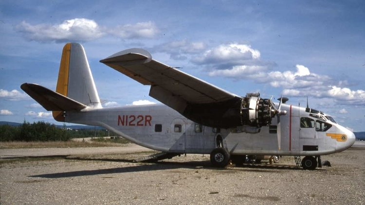 The Chase XCG-18A and YC-122 Avitruc (known internally as the Chase MS.7) was a military transport aircraft designed by Chase Aircraft and produced in limited numbers in the United States in the late 1940s, initially as a glider, but definitively in powered form. The design was based on the CG-14 cargo glider but was substantially larger and featured all-metal construction. It was a high-wing cantilever monoplane. The fuselage was of rectangular cross-section and featured a loading ramp at its rear. The main undercarriage units were carried at the sides of the fuselage and were fixed, while the nosewheel was retractable. In its powered form, two radial engines were fitted in nacelles in the wings. The USAAF's experiences with cargo gliders during World War II indicated a role for a similar aircraft in the post-war inventory, but one capable of carrying a substantially heavier load and with greater recoverability than the essentially expendable wartime wooden assault gliders. Chase's CG-14 was selected as a starting point, and in January 1947, the USAAF placed an order for an enlarged, metal version of this aircraft, initially designated XCG-14B but redesignated to XCG-18A to reflect the basically all-new nature of the aircraft. When the prototype flew that December, it was the world's first all-metal transport glider. One of the major improvements was the use of a thinner wing section which allowed high tow speeds and small aircraft like the P-47 fighter being able to tow it into the air and to its release point. In March 1948, the service (now the USAF) ordered four more aircraft under the new designation XG-18A and a fifth to be fitted with engines as the YC-122. The air force eventually lost interest in purchasing assault gliders, but continued with the development of the powered variant, purchasing two more examples for evaluation as the YC-122A and redesignating the second of these as the YC-122B when the original Pratt & Whitney engines were swapped for Wright units. This aircraft would form the basis for the definitive service trials version, the YC-122C. Nine of these aircraft were ordered and although they performed well in evaluation (first at Sewart AFB, Tennessee, later at Ardmore AFB, Oklahoma), the USAF no longer saw a need for a small transport aircraft and cancelled the project. Despite the short-lived history of the aircraft, it was used extensively at Ardmore AFB. By February 1955, at least one pilot, Captain Phillip C. Gromley of the 16th Troop Carrier Squadron, 463rd Troop Carrier Wing, achieved 1,000 hours in piloting the aircraft. All aircraft were replaced by Fairchild C-123B Providers by July 1955. The last YC-122C assault transport was flown to Tucson, Arizona, on 30 August 1955, for storage at Davis-Monthan AFB. Captain Gromely is recorded as making the final flight of a YC-122C to Tucson. The remaining machines served on in utility roles until 1957. Following their retirement, the fuselage of one of the YC-122s was used in the construction of the Hiller X-18. Variants Chase MS.7 Company designation for the XCG-14B / XCG-18A XCG-18A XCG-14B re-designated XG-18A revised glider version (4 built) YC-122 prototype powered version, an XG-18A with Pratt & Whitney R-2000-11 engines (one built) YC-122A refined version of the YC-122 (two built) YC-122B YC-122A re-engined with Wright R-1820-101 engines (one converted) YC-122C definitive service trials version (nine built)1 point
 -
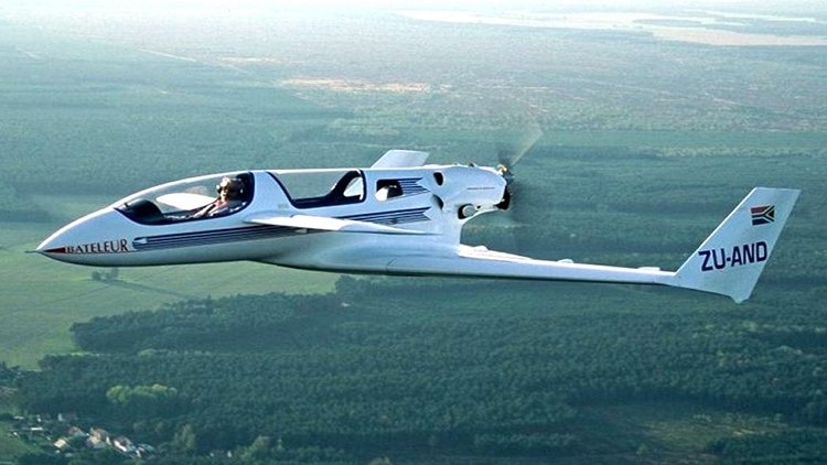 The RMT Bateleur (named for the bird species) is a German ultralight and light-sport aircraft, designed by Andre von Schoenebeck and produced by RMT Aviation of Bad Bocklet. The aircraft is supplied as a kit for amateur construction or as a complete ready-to-fly-aircraft. The aircraft was designed by von Schoenebeck as his first full-sized aircraft after a career of designing competition model gliders. The Bateleur was intended to comply with the Fédération Aéronautique Internationale microlight rules and US light-sport aircraft rules. The company also plans to type certify it to FAR 23 standards. The Bateleur features a delta wing layout with a canard. The wing is a cantilever low-wing design. The aircraft also features two-seats-in-tandem under separate bubble canopies, fixed or optionally retractable tricycle landing gear and a single engine in pusher configuration. The light-sport version will have fixed landing gear as that category's rules require and a gross weight of 600 kg (1,323 lb). The aircraft is made from composites. Its 6.25 m (20.5 ft) span wing has an area of 14 m2 (150 sq ft) and flaps mounted on the main and canard wings. Standard engines available are the 100 hp (75 kW) Rotax 912ULS and the turbocharged, 115 hp (86 kW) Rotax 914 four-stroke powerplants. Landing gear is fixed for the US light-sport aircraft market or retractable for the homebuilt version. Production was initially established in South Africa, moved to Germany, and finally to the United States in 2012. As of March 2017, the design does not appear on the Federal Aviation Administration's list of approved special light-sport aircraft.1 point
 -
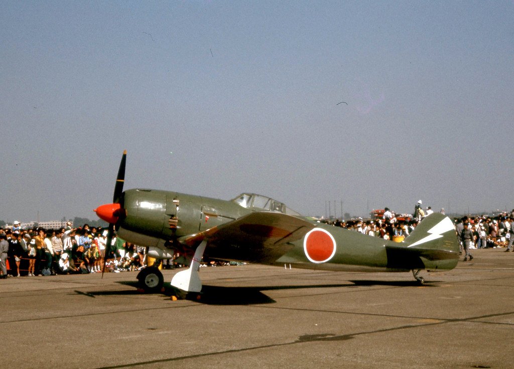 The Nakajima Ki-84 Hayate (キ84 疾風, lit. "Gale") is a single-seat fighter flown by the Imperial Japanese Army Air Service in the last two years of World War II. The Allied reporting name was "Frank"; the Japanese Army designation was Army Type 4 Fighter (四式戦闘機, yon-shiki-sentō-ki). The Ki-84 is generally considered the best Japanese fighter to operate in large numbers during the conflict. The aircraft boasted high speed and excellent maneuverability with an armament (up to two 30 mm and two 20 mm cannon) that gave it formidable firepower. The Ki-84's performance matched that of any single-engine Allied fighter it faced, and its operational ceiling enabled it to intercept high-flying B-29 Superfortress bombers. Pilots and crews in the field learned to take care with the plane's high-maintenance Nakajima Homare engine and landing gear prone to buckling. The difficulties of Japan's situation late in the war took a toll on the aircraft's field performance as manufacturing defects multiplied, good quality fuel proved difficult to procure, and experienced pilots grew scarce. Nevertheless, a well-maintained Ki-84 was Japan's fastest fighter. A total of 3,514 aircraft were built. Design of the Ki-84 commenced in early 1942 to meet an Imperial Japanese Army Air Service requirement for a replacement to Nakajima's own, earlier Ki-43 fighter, then just entering service. The specification recognized the need to combine the maneuverability of the Ki-43 with performance to match the best western fighters, and heavy firepower. The Ki-84 first flew in March 1943[6] and deliveries from Nakajima's Ota factory commenced the following month. Although the design was itself solid, growing difficulties in securing skilled pilots, proper fuel and construction materials, and adequate manufacture often prevented the aircraft from reaching its full potential in the field. The design of the Ki-84 addressed the most common complaints about the popular and highly maneuverable Ki-43: insufficient firepower, poor defensive armor, and lack of climbing speed. The Ki-84 was a cantilever low-wing monoplane of all-metal construction, except for the fabric-covered control surfaces, with conventional landing gear.[8] Armament comprised two fuselage-mounted, synchronized 12.7 mm (.50 in) machine guns — these proved challenging to synchronize properly with the Hayate's four-blade propeller — and two wing-mounted 20 mm cannon, a considerable improvement over the two 12.7 mm (.50 in) machine guns used in the Ki-43 Hayabusa. Defensive armor offered Hayate pilots better protection than the unsealed wing tanks and light-alloy airframe of the Ki-43. In addition, the Ki-84 used a 65 mm (2.56 in) armor-glass canopy, 13 mm (.51 in) of head and back armor, and multiple bulkheads in the fuselage, which protected both the methanol-water tank (used to increase the effectiveness of the supercharger) and the centrally located fuel tank. It was the Nakajima firm's own-designed 35.8-litre (2,180 cu in) displacement, Ha-45 Homare ("Praise" or "Honor") air-cooled eighteen-cylinder radial engine, first accepted for military use in 1941, that gave the Hayate its high speed and prowess in combat. Derived from the Nakajima Homare engines common to many Japanese aircraft, the Hayate used several versions of the Homare engine, including the carbureted model 21 and the fuel-injected model 23 versions of the engine. Most Homare engines used water injection to aid the supercharger in giving the Ki-84 a rated 1,491 kW (2,000 hp) at takeoff. This combination theoretically gave it a climb rate and top speed roughly competitive with the top Allied fighters. Initial Hayate testing at Tachikawa in early summer 1943 saw test pilot Lieutenant Funabashi reach a maximum level airspeed of 624 km/h (387 mph) in the second prototype. In 1946, US Technical Intelligence bench-tested a Homare 45, Model 21 engine and verified the engine's maximum horsepower output using 96 octane AvGas, plus methanol injection. The first major operational involvement was during the battle of Leyte at the end of 1944, and from that moment until the end of the Pacific war the Ki-84 was deployed wherever the action was intense. The 22nd Sentai re-equipped with production Hayates. Though it lacked sufficient high-altitude performance, it performed well at medium and low levels. Seeing action against the USAAF 14th Air Force, it quickly gained a reputation as a combat aircraft to be reckoned with. Fighter-bomber models also entered service. On April 15, 1945, 11 Hayates attacked US airfields on Okinawa, destroying many aircraft on the ground. In the final year of the war the Ki-84, the Ki-100 (essentially a radial-engined version of the inline-powered Kawasaki Ki-61) and Kawanishi's N1K2-J were the three Japanese fighters best suited to combat the newer Allied fighters. For details of the 18 variants, click here. A total of 3,413 units were produced.1 point
 -
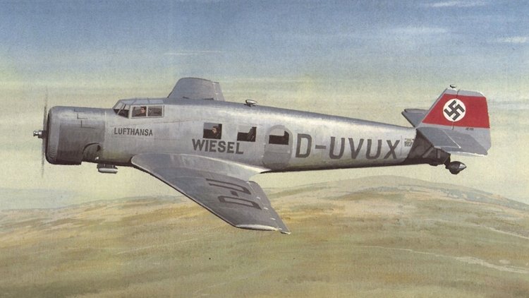 The Junkers Ju 60 was a single engine airliner built in prototype form in Germany in the early 1930s. It was designed to meet a requirement issued by the Reichsverkehrsministerium (Reich Transport Ministry) for a German-built equivalent to the Lockheed Vega with which to equip Deutsche Luft Hansa. The result was a sleek, cantilever monoplane of conventional configuration, with wings skinned in the corrugated duralumin that had been a hallmark of Junkers designs up to this time, although this would be the last Junkers aircraft to have this feature. The main units of the tailwheel undercarriage were retractable. The Ju 60 was evaluated by Deutsche Luft Hansa against the Heinkel He 70. With the latter able to demonstrate a top speed 75 km/h (47 mph) better than the Ju 60, development of the Junkers design was halted before the third prototype had been completed. The two examples that had already been constructed eventually saw service with the Luftwaffe as liaison aircraft until 1942. The work done on the design would later form the basis of the Ju 160.1 point
 -
01.jpg.a34cd2b8c27e97e596776f027333a502.jpg) The Lockheed XFV (sometimes referred to as the "Salmon") was an American experimental tailsitter prototype aircraft built by Lockheed in the early 1950s to demonstrate the operation of a vertical takeoff and landing (VTOL) fighter for protecting convoys. The Lockheed XFV originated as a result of a proposal issued by the U.S. Navy in 1948 for an aircraft capable of vertical takeoff and landing (VTOL) aboard platforms mounted on the afterdecks of conventional ships. Both Convair and Lockheed competed for the contract but in 1950, the requirement was revised, with a call for a research aircraft capable of eventually evolving into a VTOL ship-based convoy escort fighter. On 19 April 1951, two prototypes were ordered from Lockheed under the designation XFO-1 (company designation was Model 081-40-01). Soon after the contract was awarded, the project designation changed to XFV-1 when the Navy's code for Lockheed was changed from O to V. The XFV was powered by a 5,332 hp (3,976 kW) Allison YT40-A-6 turboprop engine driving three-bladed contra-rotating propellers. The tail surfaces were a reflected cruciform v-tail (forming an x) that extended above and below the fuselage. The aircraft had an ungainly appearance on the ground with a makeshift, fixed landing gear attached. Lockheed employees derisively nicknamed the aircraft the "pogo stick" (a direct reference to the rival Convair XFY's name).1 point
The Lockheed XFV (sometimes referred to as the "Salmon") was an American experimental tailsitter prototype aircraft built by Lockheed in the early 1950s to demonstrate the operation of a vertical takeoff and landing (VTOL) fighter for protecting convoys. The Lockheed XFV originated as a result of a proposal issued by the U.S. Navy in 1948 for an aircraft capable of vertical takeoff and landing (VTOL) aboard platforms mounted on the afterdecks of conventional ships. Both Convair and Lockheed competed for the contract but in 1950, the requirement was revised, with a call for a research aircraft capable of eventually evolving into a VTOL ship-based convoy escort fighter. On 19 April 1951, two prototypes were ordered from Lockheed under the designation XFO-1 (company designation was Model 081-40-01). Soon after the contract was awarded, the project designation changed to XFV-1 when the Navy's code for Lockheed was changed from O to V. The XFV was powered by a 5,332 hp (3,976 kW) Allison YT40-A-6 turboprop engine driving three-bladed contra-rotating propellers. The tail surfaces were a reflected cruciform v-tail (forming an x) that extended above and below the fuselage. The aircraft had an ungainly appearance on the ground with a makeshift, fixed landing gear attached. Lockheed employees derisively nicknamed the aircraft the "pogo stick" (a direct reference to the rival Convair XFY's name).1 point -
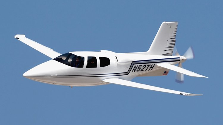 The Cirrus VK-30 is a single-engine pusher-propeller homebuilt aircraft originally sold as a kit by Cirrus Design (now Cirrus Aircraft), and was the company's first model, introduced in 1987. As a kit aircraft, the VK-30 is a relatively obscure design with few completed aircraft flying. Its most important legacy is that the work done on developing and marketing the aircraft convinced the designers, the Klapmeier brothers, that the best way to proceed in the future was with a more conventional layout and with a certified production aircraft. Thus the lessons of the VK-30 were directly responsible for the design of the Cirrus SR20 and SR22, which have been the best-selling general aviation airplanes in the world every year since 2003. The VK-30 also served as a significant inspiration for the creation of the company's latest aircraft, the Cirrus Vision Jet, which in 2018 won the Collier Trophy for becoming the first single-engine personal jet with a whole-plane parachute recovery system. The VK-30 design was conceived in the early 1980s as a kit plane project by three Wisconsin college students: Alan Klapmeier and Jeff Viken from Ripon College, and Alan's brother, Dale Klapmeier, who was attending the University of Wisconsin–Stevens Point. Together after college, in the Klapmeier brothers' parents' dairy barn in rural Sauk County, Wisconsin, they formed Cirrus Design in 1984 as the company to produce the VK-30 ("VK" standing for Viken-Klapmeier). Jeff's wife, Sally Viken, designed the aircraft's flap system. During the kit's early developmental phase, the Klapmeiers and Vikens sought frequent help and advice from homebuilt innovator Molt Taylor, who specialized in pusher configurations dating back to the 1940s. The aircraft has an all-composite construction and was designed to achieve natural laminar flow over the fuselage, wing and tail surfaces to provide for very low drag—using a NASA NLF(1)-0414F airfoil designed by Jeff Viken. The original prototype incorporated scrapped parts from production aircraft out of junkyards the Klapmeier brothers visited in order to reduce cost, including both a control system and nose landing gear from a Piper Cherokee (welding parts onto it to convert it to a retractable gear), as well as an O-540 (290 hp) engine off a wrecked de Havilland Heron. The VK-30 was designed to be a five-seat aircraft from the start, which made it considerably larger than most other amateur-built aircraft of its day. It incorporated a mid-engine design, driving a three-bladed pusher propeller behind the tail through an extension shaft. The powerplant in later models was a Continental IO-550-G piston engine developing 300 hp (224 kW). The VK-30 was introduced at the 1987 EAA AirVenture Oshkosh convention in Oshkosh, Wisconsin, and first flew on 11 February 1988. Kit deliveries commenced shortly thereafter. In the late 1980s, the Klapmeier brothers approached jet engine manufacturer Williams International about the possibility of installing a small, single Williams FJ44 turbofan engine on the VK-30. The idea never materialized at that time, however, it significantly inspired the original design concept of the Vision Jet in the mid-2000s. Cirrus discontinued production of the aircraft in 1993, and in 1996, announced plans to develop a stronger replacement wing for about 28 VK-30s supplied to past customers. Cirrus delivered about 40 kits, and built four additional factory prototypes. The company estimated that there were 13 customer VK-30s completed. As of 11 February 2018, four were still registered with the Federal Aviation Administration in the US, although at one time a total of 12 had been registered. Variants Cirrus/Israviation ST50 The VK-30 was the predecessor of the Cirrus ST50, which had an almost-identical configuration to the VK-30, but included a larger ventral fin on the tail of the aircraft, a slightly larger fuselage, and was powered by a Pratt & Whitney Canada PT6-135 turboprop engine in place of the piston engine used in the VK-30. Cirrus designed and initially developed the aircraft under contract to an Israeli aircraft manufacturer named Israviation, and first flew it in Duluth, Minnesota in 1994. Isravation attempted to certify and market the ST50 in the proceeding years but it never entered production by the company.1 point
 -
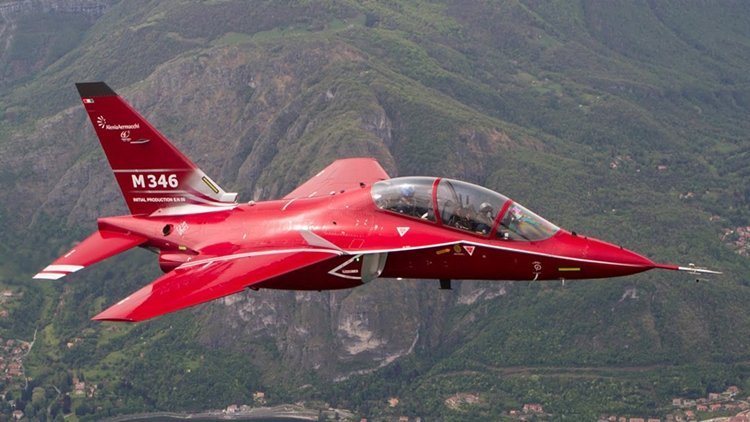 The Aermacchi M-346 Master is a family of military twin-engine transonic advanced jet trainers and light combat aircraft. Originally co-developed with Yakovlev as the Yak/AEM-130, the partnership was dissolved in 2000 and then Alenia Aermacchi proceeded to separately develop the M-346 Master, while Yakolev continued work on the Yakovlev Yak-130. The first flight of the M-346 was performed in 2004. The type is currently operated by the air forces of Italy, Israel, Singapore, Greece, Turkmenistan and Poland. Since 2016 the manufacturer became Leonardo-Finmeccanica as Alenia Aermacchi merged into the new Finmeccanica, finally rebranded as Leonardo in 2017. The M-346 is designed for the main role of lead-in fighter trainer, in which aircraft's performance and capabilities are used to deliver pilot training for the latest generation of combat fighter aircraft. Powered by a pair of Honeywell F124 turbofan dry engines, designed to reduce acquisition and operating costs, it is capable of transonic flight without using an afterburner; Alenia Aermacchi has claimed that the M-346's flight performance to be "second only to afterburner-equipped aircraft". During the design process, the twin concepts of "design-to-cost" and "design-to-maintain" were adhered to, reducing acquisition and operational costs; the per flying hour costs of the M346 are reportedly one-tenth of those of the Eurofighter Typhoon. Outside of the training role, the M-346 was designed from the onset to accommodate additional operational capabilities, including combat missions such as close air support and air policing duties. The combat capable M-346FA can perform ground attack, homeland defence and air policing missions and reconnaissance. Various munitions and stores can be carried, including IRIS-T or AIM-9 Sidewinder air-to-air missiles, various air-to-surface missiles, anti-ship missiles, free-fall and laser-guided bombs and rockets, a 12.7 mm gun pod, reconnaissance and targeting pods, and electronic warfare pods; weapon aiming is performed using the Helmet Mounted Display and the multifunction displays. All main systems are duplicated, and the flight system reconfigurable, to increase survivability and functionality in the event of battle damage being sustained.[28] The aircraft has a maximum range of 1,375 nautical miles when outfitted with a maximum of three external fuel tanks, this can be extended via in-flight refuelling via a removable refuelling probe. For more details of the design and operational history of the M-346, click here. Variants M-346 Designation for the basic type. T-346A Italian military designation from 2012 for the M-346. M-346LCA (Light Combat Aircraft) Armed variant offered to Poland as a replacement for aging Su-22. Designation no longer in use. M-346FT (Fighter Trainer) Multirole variant capable of switching between training and combat operations. New features include a new tactical datalink system and different armament capability, but do not include physical changes to the hardware. M-346FA (Fighter Attack) Multirole variant capable of air-to-air and air-to-surface combat with a 3 tonne payload spread over 7 hardpoints, advanced Grifo-M346 radar radar, countermeasures and stealth features including engine intake grids and radar-absorbing coatings on the canopy and wing leading edge. It is being marketed as a light attack aircraft also suitable for aggressor and companion training purposes. The aircraft was revealed on June 18, 2017, in a static display at that year's Paris Air Show. The aircraft is being marketed for export to South American and East Asian countries, and is claimed to be able to carry out operational missions at far lower costs than those of front-line fighters. T-100 Designation used for the United States Air Force's T-X program.1 point
 -
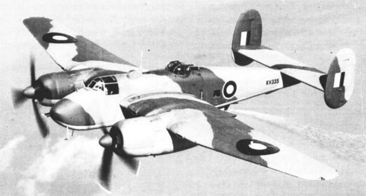 The Bristol Type 163 Buckingham was a British Second World War medium bomber for the Royal Air Force (RAF). Overtaken by events, it was built in small numbers and was used primarily for transport and liaison duties. In early 1939 Bristol suggested a bomber variant of the Beaufighter with their Hercules engines. British policy at the time was for medium bombers to be obtained from the US allowing British industry to concentrate on heavy bomber designs; nonetheless a design was requested preferably based on an existing aircraft. This meant working with the Beaufighter or Beaufort. Bristol worked on their design first as the Bristol Type 161 then the Type 162 Beaumont. Air Ministry specification B.7/40 called for a medium bomber to replace the Blenheim. The specification stipulated a speed of at least 300 mph at 5,000 ft, a normal load of 1,000 lb of bombs and a centre turret armed with at least two 0.5 inch (12.7 mm) machine guns. Only one manufacturer (Armstrong Whitworth) tendered a full design but it did not meet with approval. So when Bristol brought their Type 162 ("tentatively named Beaumont"), which was well matched to B.7/40, to the Air Staff, the company received a request to complete a mockup in 1940 and then a confirmed contract for three prototypes in February 1941. The Beaumont was based on the rear fuselage and tail of a Beaufighter, with a new centre and front fuselage. The armament was a mid-upper turret with four machine guns, with four more machine guns firing forward and two firing to the rear. Construction began in late 1940, with a new Air Ministry Specification B.2/41 to be written around it. Changes in the requirements, removing dive bombing and "direct army support" which incoming US bombers were expected to be capable of and increasing the performance to allow for the future, meant the Beaumont would no longer suffice. The changes in performance (requiring a bomb load of 4,000 lb, a speed of 360 mph and a range of 1,600 miles) meant a redesign by Bristol to use the Bristol Centaurus engine. The Bristol redesign with a larger wing and the more powerful engines was the Type 163 Buckingham. It had gun installations in the nose, dorsal and ventral turrets. Generally conventional in appearance, one unusual feature was that the bomb-aimer/navigator was housed in a mid-fuselage ventral gondola, resembling those on the earlier German Heinkel He 111H and American Boeing B-17C and -D in appearance. This was part of an attempt to give all the crew positions unobstructed views and access to each other's positions. The bomb bay could hold a 4,000 lb, two 2,000 lb, four 1,000 lb or six 500-lb bombs. The rear of the gondola had a hydraulically powered turret with two 0.303 Browning machine guns. The Bristol-designed dorsal turret carried four Brownings. A further four fixed, forward-firing Brownings were controlled by the pilot. Following more changes, specification B.2/41 was replaced by B.P/41. An order for 400, at an initial rate of 25 per month, was made with deliveries expected in March 1943 but Bristol were still concerned that this not a reasonable scale and would prove expensive, and as such complained to MAP about poor planning. The first flight took place on 4 February 1943. During testing, the Buckingham exhibited poor stability which led to the enlargement of the twin fins, along with other modifications. Variants Type 163 Buckingham Prototypes with two Centaurus IV engines, four built. Type 163 Buckingham B1 Production variant first flown 12 February 1944 with Centarus VI or XI engines, 400 ordered but reduced first to 300 then to 119, with only 54 built as bombers. Type 163 Buckingham C1 (Specifications below) Residual production completed as fast courier transport with four-passenger seats and removal of armour and armament and increased fuel tankage, 64 built. Type 164 Brigand Torpedo bomber variant using Buckingham wings and tails and new fuselage. Type 165 Brigand II Trainer variant of the Brigand, not built. Type 166 Buckmaster Trainer variant of the Buckingham. Type 169 Proposed photo-reconnaissance variant of the Buckingham, not built.1 point
 -
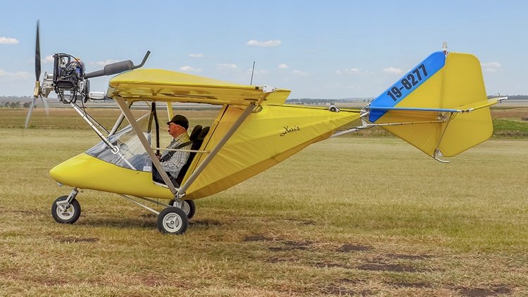 The Raj Hamsa X-Air is an Indian, two-seat, high-wing, tricycle gear, tractor configuration, ultralight aircraft produced by Raj Hamsa Ultralights of Bangalore, Karnataka in kit form, for amateur construction. The X-Air started as a development of the Chotia Weedhopper redesigned to incorporate ailerons and an enclosed cabin. After initial production in Europe manufacturing was shifted to Raj Hamsa in India. In many countries the aircraft is known as the Rand Kar X-Air. In the USA it is sometimes referred to as the Light Wing X-Air. The aircraft was later developed into the more conventional X-Air Hanuman, which relocated the engine from the upper keel tube to the nose. The X-Air is built from bolted aluminium tubing, mated to a central welded steel cockpit cage. The wings and tail surfaces are covered in pre-sewn Dacron sailcloth envelopes. The aircraft is built around its keel, a large tube that runs from the high-mounted engine in the front to the tail in the back. The wings are supported by V-struts with jury struts. The landing gear incorporates oleo shock absorbers on all three wheels. The nosewheel is steerable and mainwheel brakes are standard. Dual controls are standard, but cockpit doors are optional. The cockpit has been criticized by reviewer Andre Cliche as "a bit difficult to access". The X-Air can be fitted with either floats or skis. Engines from 50 to 75 hp (37 to 56 kW) can be fitted, provided they weigh under 120 lb (54 kg). The construction time is estimated at 40 hours. Due to its low price and BCAR Section "S" certification the X-Air has proven popular in the United Kingdom. An X-Air has been used as a testbed for the prototype D-Motor LF26 flathead engine. Variants X-Air "S" (Standard) Specifications below. Initial version, certified under UK BCAR Section "S" as a microlight. Standard engine is the 64 hp (48 kW) Rotax 582 and the 80 hp (60 kW) Rotax 912UL, 85 hp (63 kW) Jabiru 2200 and the 60 hp (45 kW) HKS 700E four-stroke powerplants are also used. The design is popular in the UK, especially with the Jabiru engine. X-Air "F" Gumnam Improved version, aerodynamically cleaned up, extended fuselage with baggage compartment, Lexan doors and wheel pants are standard. The wing is 1 m (39 in) shorter, with a higher aspect ratio, 100% double surface, flaps and a NACA 4412 airfoil. Certified under UK BCAR Section "S" as a microlight and marketed in the UK as the X-Air Falcon. Standard engine is the 64 hp (48 kW) Rotax 582, although the 50 hp (37 kW) Rotax 503 or 85 hp (63 kW) Jabiru 2200 four-stroke engine can be used. X-Air "H" Hanuman See separate profile Development version, with nose-mounted 85 hp (63 kW) Jabiru 2200 four-stroke engine.1 point
 -
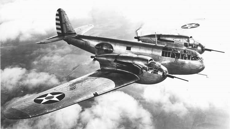 The Bell YFM-1 Airacuda was an American heavy fighter aircraft, developed by the Bell Aircraft Corporation during the mid-1930s. It was the first military aircraft produced by Bell. Originally designated the Bell Model 1, the Airacuda first flew on 1 September 1937. The Airacuda was marked by bold design advances and considerable flaws that eventually grounded the aircraft. The Airacuda was Bell Aircraft's answer for a "bomber destroyer" aircraft. Although it did see limited production, and one fully operational squadron was eventually formed, only one prototype and 12 production models were ultimately built, in three slightly different versions. In an effort to break into the aviation business, Bell Aircraft created a unique fighter concept touted to be "a mobile anti-aircraft platform" as well as a "convoy fighter." Created to intercept enemy bombers at distances beyond the range of single-seat fighter interceptors, the YFM-1 (Y, service test; F, fighter; M, multiplace) was an innovative design incorporating many features never before seen in a military aircraft, as well as several never seen again. Using a streamlined, "futuristic" design, the Bell Airacuda appeared to be "unlike any other fighters up to that time." According to Major Alexander De Seversky's 1942 book, Victory Through Air Power, the Bell Airacuda "represents a great engineering achievement. But its designation as ′convoy fighter′ is erroneous, since that requires different disposition of armament. With its maximum firepower directed forward, it really offers a preview of an effective long-range interceptor fighter." A forward-firing 37 mm (1.46 in) M4 cannon with an accompanying gunner was mounted in a forward compartment of each of the two engine nacelles. Although capable of aiming the cannons, the gunners' primary purpose was simply to load them with the 110 rounds of ammunition stored in each nacelle. The crew of five included the pilot and gunners; a copilot/navigator who doubled as a fire-control officer, using a Sperry Instruments "Thermionic" fire control system (originally developed for anti-aircraft cannon) combined with a gyro-stabilised and an optical sight to aim the weapons; and a radio operator/gunner armed with a pair of machine guns stationed at mid-fuselage waist blisters for defense against attack from the rear. An unusual feature of the Airacuda was the main door for entry. The door was opened and pulled down and hinges folded in on three steps for the crew to climb into the aircraft. For more information on design flaws, accidents and variants, click here.1 point
 -
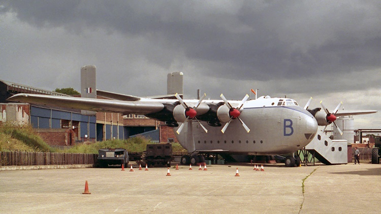 The aircraft was a high-wing cantilever monoplane with a fixed undercarriage. The large fuselage had a tailboom and tailplane with twin fins. The tailboom allowed access to the rear of the fuselage through removable clamshell doors. A 36 ft (11 m) main fuselage space was supplemented by passenger accommodation in the tailboom. The main cargo hold could accommodate 94 troops, with another 36 in the tailboom. In operation, it was regarded as "ungainly but highly effective" and was described by Air Chief Marshal Sir Robert Freer as "like something out of the Ark, but it was a superb supply dropper." A device called an Elephant's Foot could be fitted under the centre of the fuselage just forward of the clamshell doors when loading heavy items to prevent the aircraft from tipping back. The aircraft was designed for carrying large bulkloads and landing on rough or imperfect runways, or dirt strips. It could trace its design back to the GAL49 Hamilcar glider of the Second World War. When it entered service it was the largest aircraft in the Royal Air Force (RAF). It had a large cargo hold of about 6,000 ft3 (170 m3). Paratroopers in the upper passenger area jumped through a hatch in the base of the boom just in front of the leading edge of the tailplane. Paratroopers in the cargo hold exited through side doors. For more details including operational history and variants, click here.1 point
 -
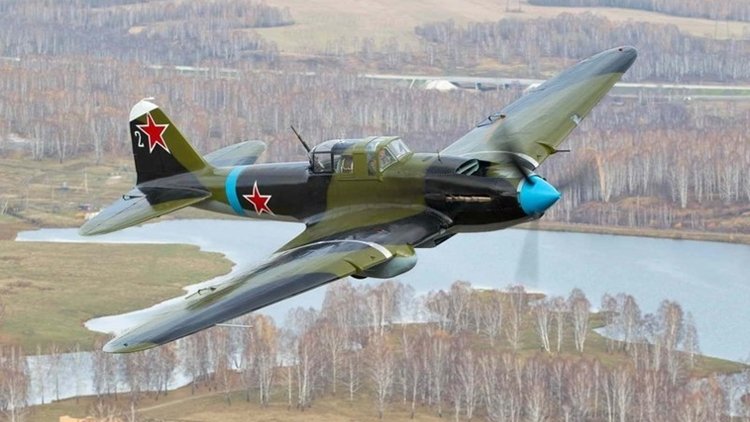 The Ilyushin Il-2 (Cyrillic: Илью́шин Ил-2) Shturmovik (Cyrillic: Штурмови́к, Shturmovík) is a ground-attack aircraft produced by the Soviet Union in large numbers during the Second World War. The Il-2 was never given an official name and 'shturmovik' is the generic Russian word meaning ground attack aircraft. The word also appears in Western sources as Stormovik and Sturmovik, neither of which give correct pronunciation in English. The Il-2 is a single-engine, propeller-driven, low-wing monoplane of mixed construction with a crew of two (one in early versions), specially designed for assault operations. Its most notable feature was the inclusion of armor in an airframe load-bearing scheme. Armor plates replaced the frame and paneling throughout the nacelle and middle part of the fuselage, and an armored hull made of riveted homogeneous armor steel AB-1 (AB-2) secured the aircraft's engine, cockpit, water and oil radiators, and fuel tanks. In early 1941, the Il-2 was ordered into production at four factories, and was eventually produced in greater numbers than any other military aircraft in aviation history, but by the time Nazi Germany invaded the Soviet Union on 22 June 1941, only State Aviation Factory 18 at Voronezh and Factory 381 at Leningrad had commenced production, with 249 having been built by the time of the German attack. For more details on development, operational history and 12 variants, click here.1 point
 -
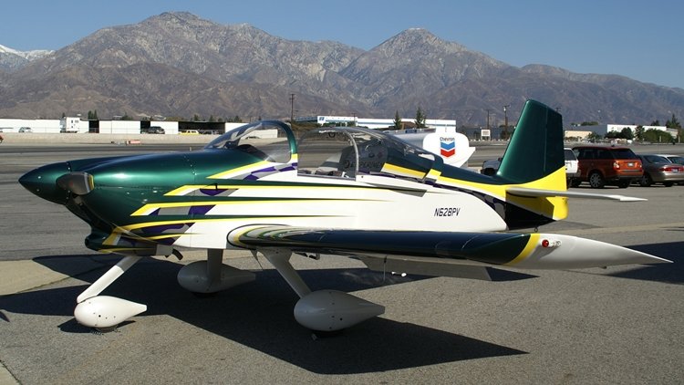 The Van's RV-6 and RV-6A are two-seat, single-engine, low-wing homebuilt airplanes sold in kit form by Van's Aircraft. The RV-6 is the tail-wheel equipped version while the RV-6A features a nose-wheel. The RV-6 was the first aircraft in the popular Van's RV series to feature side-by-side seating and the first to offer a nosewheel option. It was first flown in 1985. Over 2700 kits have been completed and flown. The RV-6 and RV-6A were replaced by the similar, but improved, RV-7 in 2001. Kit components are still available to allow builders to complete RV-6s under construction, but no new complete kits are available. Van's Aircraft designer, Richard VanGrunsven, designed the RV-6 series as a two-seat side-by-side development of the RV-4, which was itself a development of the single seat RV-3. Market demand motivated VanGrunsven to design the RV-6 and offer it as an optional nosewheel design. The original two seater RV-4 has been a remarkable success, but the tandem seating configuration was not considered ideal by many potential owners as it leaves the passenger isolated in the back seat. Many spouses of builders especially favoured the side-by-side configuration over the tandem arrangement. VanGrunsven worked diligently to create a side-by-side design with a generous 43-inch-wide (1,100 mm) cockpit that did not sacrifice the RV-4's handling, STOL performance and especially its high cruise speed. In the end the RV-6 prototype produced cruise speeds that are only 3 mph (5 km/h) slower than the RV-4 with the same engine. The first RV-6s had a forward hinged canopy design. This was a simple one-piece arrangement, but it made taxiing the aircraft with the canopy open more difficult. Later kits had the option of a rearward sliding canopy that could more easily provide ventilation on the ground. One RV-6A was modified for open cockpit flight with an enclosed rear turtledeck. The RV-6A version features steel rod landing gear with the nosewheel strut attached to the engine mount. The nosewheel is friction castering and the aircraft is steered with differential braking. The brakes are mounted conventionally on the rudder pedal toes. RV-6 RV-6A Specifications are for the RV-6 model.1 point
 -
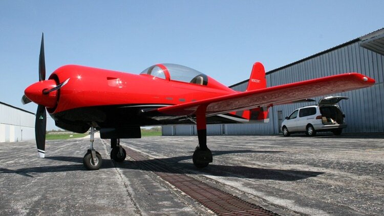 The Altitude Radial Rocket is an American amateur-built aircraft, produced by the Altitude Group of Overland Park, Kansas. The aircraft is supplied as a kit for amateur construction. The aircraft features a cantilever low-wing, a two-seats-in-tandem enclosed cockpit under a bubble canopy, fixed conventional landing gear or retractable tricycle landing gear and a single radial engine in tractor configuration. The aircraft is made from composites. The wing span and area as well as gross weight varies depending on the model. The Radial Rocket's recommended engine power range is 360 to 400 hp (268 to 298 kW) and the standard engine used is the 360 hp (268 kW) Vedeneyev M-14P four-stroke powerplant. As of 2017, six examples had been registered in the United States with the Federal Aviation Administration. Variants Radial Rocket RG Retractable tricycle gear model. It has a 26.8 ft (8.2 m) span wing, a wing area of 93.9 sq ft (8.72 sq m) and a gross weight of 2,575 lb (1,168 kg). Construction time from the supplied kit is 2000 hours. Two were reported flying by the end of 2011. (Specifications below) Radial Rocket TD Fixed taildragger gear model. It has a 25.5 ft (7.8 m) span wing, a wing area of 90.8 sq ft (8.44 sq m) and a gross weight of 2,550 lb (1,160 kg). Construction time from the supplied kit is 1900 hours. Four were reported flying by the end of 2011. Radial Rocket RG Radial Rocket TD1 point
 -
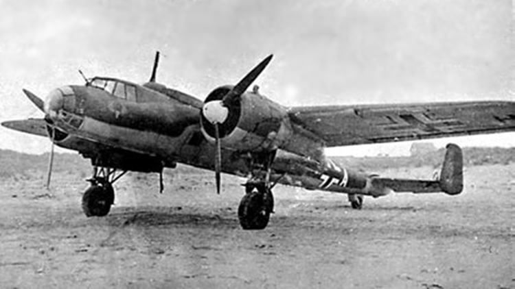 The Dornier Do 17, is a twin-engined light bomber produced by Dornier Flugzeugwerke for the German Luftwaffe during World War II. Designed in the early 1930s as a Schnellbomber ("fast bomber") intended to be fast enough to outrun opposing aircraft, the lightly built craft had a twin tail and "shoulder wing". Sometimes referred to as the Fliegender Bleistift ("flying pencil"), it was popular among its crews due to its handling, especially at low altitude, which made the Do 17 harder to hit than other German bombers. The Do 17 made its combat debut in 1937 during the Spanish Civil War, operating in the Condor Legion in various roles. Along with the Heinkel He 111 it was the main bomber type of the German air arm in 1939–1940. The Dornier was used throughout the early war, and saw action in significant numbers in every major campaign theatre as a front line aircraft until the end of 1941, when its effectiveness and usage was curtailed as its bomb load and range were limited. Production of the Dornier ended in mid-1940, in favour of the newer and more powerful Junkers Ju 88. The successor of the Do 17 was the much more powerful Dornier Do 217, which started to appear in strength in 1942. Some remaining Do 17s continued in various Luftwaffe roles until the end of the war, as a glider tug, research, and trainer aircraft. A considerable number were sent to other Axis nations, with few surviving the war. The last was scrapped in Finland.Number built: 2,139. The forward fuselage had a conventional stepped cockpit, with a fully glazed nose. Early variants were labelled the "flying pencil" owing to its sleek and continuous "stick-like" lines. As a result of the lessons learned in the Spanish Civil War, the cockpit roof was raised and the lower, or bottom half, of the crew compartment was a typical under-nose gondola or "Bodenlafette" (abbreviated Bola): this inverted-casemate design ventral defensive armament position was a common feature of most German medium bombers. The Bola was extended back to the leading edge of the wings where the lower-rear gunners position and upper-rear gunner position were level with each other. As with contemporary German bombers, the crew were concentrated in a single compartment. The cockpit layout consisted of the pilot seat and front gunner in the forward part of the cockpit. The pilot sat on the left side, close up to the Plexiglas windshield. One of the gunners sat on the right seat, which was set further back to provide room for the 7.92 mm (0.312 in) MG 15 machine gun to be traversed in use. The Do 17 usually carried a crew of four: the pilot, a bombardier and two gunners. The bomb-aimer also manned the MG 15 in the nose glazing and Bola-housed rear lower position. The two gunners operated the forward-firing MG 15 installed in the front windshield, the two MGs located in the side windows (one each side) and the rearward firing weapon. The cockpit offered a bright and panoramic view at high altitude. The standard ammunition load was 3,300 rounds of 7.92 mm ammunition in 44 double-drum magazines. For more extensive details of the development, design and variants, click here.1 point
 -
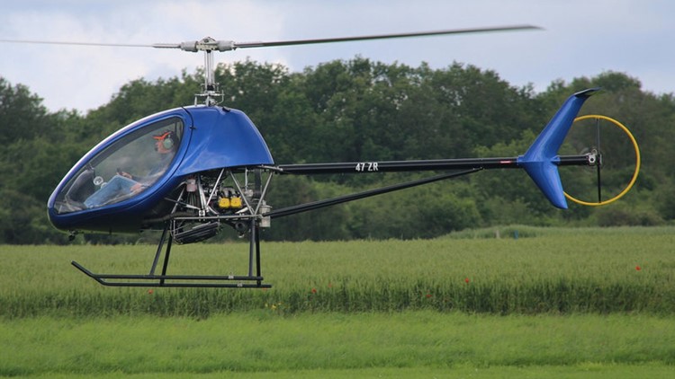 The aircraft is supplied complete and ready-to-fly-aircraft or as a kit for amateur construction. The H3 was designed for the flight training, utility and personal-use roles. It was designed to comply with the European Class 6 microlight helicopter rules, in particular the French Class 6 Microlight Category, at a gross weight of 450 kg (992 lb). It features a single main rotor and tail rotor, a two-seats-in side-by-side configuration enclosed cockpit with a bubble canopy, skid landing gear and a four-cylinder, liquid and air-cooled, four stroke 100 hp (75 kW) Rotax 912ULS engine, a Dynali-developed fuel-injected 110 hp (82 kW) conversion Rotax 912ULS-1 engine or a 115 hp (86 kW) turbocharged Rotax 914 powerplant. The aircraft's gross weight varies from 450 kg (992 lb) for the microlight category, with heavier weights available depending on installed power in other national categories, such as light-sport aircraft. With the Rotax 912ULS engine, the gross weight is 500 kg (1,102 lb), 550 kg (1,213 lb) with the Rotax 912ULS-1 and 600 kg (1,323 lb) with the Rotax 914. The aircraft fuselage frame is made from welded stainless steel tubing. Its two-bladed rotor has a diameter of 7.14 m (23.4 ft) and a chord of 18.5 cm (7.3 in). With the Rotax 914 engine the aircraft has a typical empty weight of 290 kg (639 lb) and a gross weight of 600 kg (1,323 lb), giving a useful load of 310 kg (683 lb). With full fuel of 60 litres (13 imp gal; 16 US gal) the payload for the pilot, passenger and baggage is 267 kg (589 lb).1 point
 -
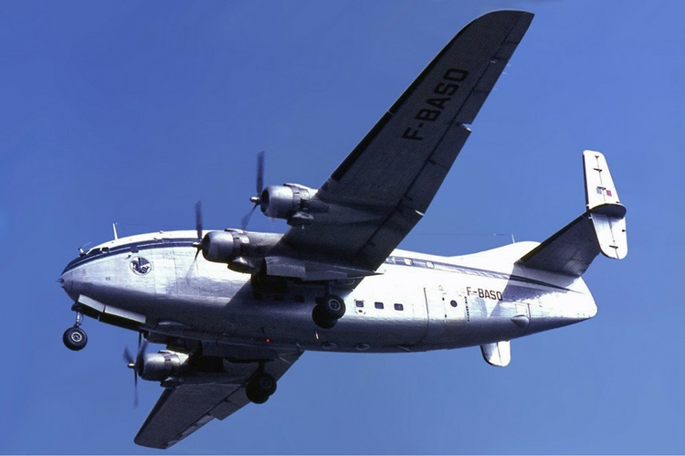 The aircraft were normally called the Deux-Ponts (Double-Decker) but it was not an official name. Bréguet began design work on the Bréguet 761 double-deck airliner even before the end of the Second World War, in 1944. It was decided that a medium-range airliner with seating for over 100 passengers would be built. The design envisaged using readily available engines with the aim of ease of manufacture and an early first-flight date. The design was known as Project 76-1. The aircraft was destined not to be the first French postwar design to fly, an honour which instead fell to the Sud-Est Languedoc, a civilianised Bloch MB161. The prototype Br.761, F-WASK, first flew at Villacoublay on 15 February 1949. The 761 featured a cantilever wing set at mid-height on the bulky fuselage. The retractable tricycle landing gear featured dual-wheel main units. The empennage had twin fins and rudders and a vestigial central fin. The prototype was powered by four 1,580 hp (1,180 kW) SNECMA 14R-24 radial engines. The Bréguets serving with Air France had up to 107 seats and an elevator between the two floors. The 763 first flew on 20 July 1951 and entered service with Air France during autumn 1952. The Air France aircraft had accommodation for 59 passengers on the top deck, and 48 on the lower deck, although the aircraft was capable of carrying 135 passengers in a high-density layout. During 1964 Air France transferred six Br.763s to the French Air Force. The air force also acquired the three pre-production Br.761S aircraft and four new Br.765 Sahara freighter aircraft with removable cargo doors. For information on the operational history and the five variants, click here.1 point
 -
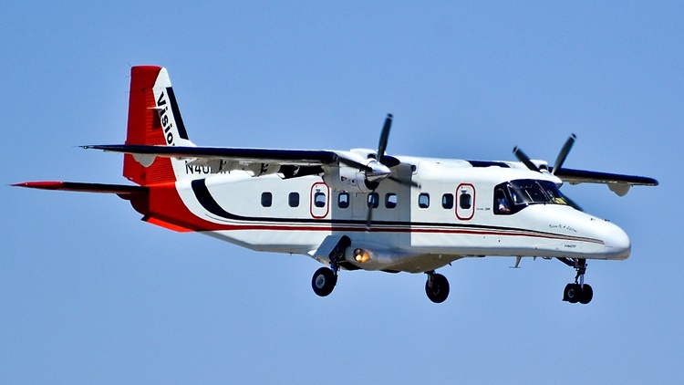 245 were built in Oberpfaffenhofen, Germany. In 1983, Hindustan Aeronautics (HAL) bought a production licence and manufactured another 125 aircraft in Kanpur, India. In July 2017, 63 aircraft were still in airline service. The Dornier 228 is a twin-engine general purpose aircraft, capable of transporting up to 19 passengers or various cargoes. It is powered by a pair of Garrett TPE331 turboprop engines. The Do 228 is commonly classified as a Short Takeoff and Landing (STOL)-capable aircraft, being capable of operating from rough runways and in hot climates. This capability has been largely attributed to the type's supercritical wing which generates large amounts of lift at slow speeds. The Do 228 is typically promoted for its versatility, low operational costs, and a high level of reliability – possessing a dispatch reliability of 99%. RUAG Aviation have claimed that no other aircraft in the same class may carry as much cargo or as many passengers over a comparable distance as fast as the Do 228 NG. (New Generation). The rectangular shape of the Do 228's fuselage section and large side-loading doors make it particularly suitable for utility operators, which is a market that Dornier had targeted with the type from the onset. According to Flight International, one of the more distinguishing features of the Do 228 is the supercritical wing used. The structure of the wing is atypical, consisting of a box formed from four integrally-milled alloy panels. Kevlar is used for the ribs, stringers, trailing edge and fowler flaps, and the wing's leading edge is conventional alloy sheet metal. Benefits of this wing over conventional methodology include a 15% reduction in weight, the elimination of 12,000 rivets, and lowering the per-aircraft manufacturing workload by roughly 340 man hours. Both the fuselage and tail are of a conventional design, but make use of chemical milling in order to save weight. For more details of the design and development of the 228 and 228NG, click here. Specifications below are for the 228NG.1 point
 -
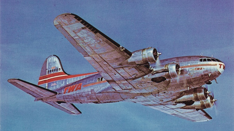 It was the first to offer a pressurized cabin, allowing it to cruise at an altitude of 20,000 ft (6,000 m), well above many weather disturbances. The pressure differential was 2.5 psi (17 kPa), so at 14,700 ft (4,480 m) the cabin air pressure was equivalent to an altitude of 8,000 ft (2,440 m). The Model 307 had capacity for a crew of six and 33 passengers. The cabin was nearly 12 ft (3.6 m) across. It was the first land-based aircraft to include a flight engineer as a crew member (several flying boats had included a flight engineer position earlier). In addition to its civilian service it was also flown as the Boeing C-75 Stratoliner by the United States Army Air Forces, who used it as a long-range cargolift aircraft. In 1935, Boeing designed a four-engine airliner based on its B-17 heavy bomber (Boeing Model 299), then in development, calling it the Model 307. It combined the wings, tail, rudder, landing gear, and engines from their production B-17C with a new, circular cross-section fuselage of 138 in (351 cm) diameter, designed to allow pressurization. The first order, for two 307s (named Stratoliners), was placed in 1937 by Pan American Airways. Pan Am soon increased this to six, and a second order for five from Transcontinental & Western Air (TWA) prompted Boeing to begin production on an initial batch of the airliner. Pan Am received its initial order and TWA received its order, but only one of the second batch of four Pan Am aircraft was delivered before war intervened and put a halt to civil aircraft production. For information on the operational history, conversion to C-75, and the five variants, and the individual histories of the 10 airframes built, click here.1 point
 -
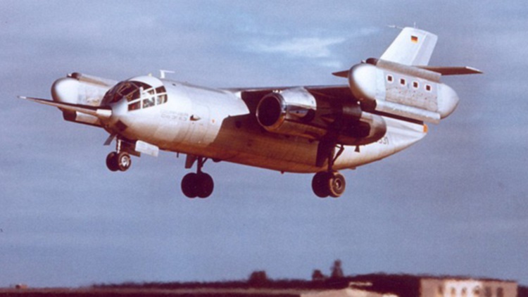 The Cold War gave rise to a number of fighter designs on both sides of the Iron Curtain that attempted to overcome the probability of sealed runways being destroyed in First Strike missions. These designs incorporated VTOL technology. While engineers were working on developing fighters, someone came up with the idea to apply the technology to military transport aircraft which could quickly deliver armed troops and equipment to hot spots. German engineers developed the Dornier Do31 for this task, and as the Cold War tensions eased, looked to applying the technology to civilian transport. For more details about the Do 31 click here, or watch the video below. This video tells the story of the D031.1 point