gregv
-
Posts
21 -
Joined
-
Last visited
Content Type
Profiles
Forums
Gallery
Downloads
Blogs
Events
Store
Aircraft
Resources
Tutorials
Articles
Classifieds
Movies
Books
Community Map
Quizzes
Everything posted by gregv
-
Hi Kai The 3300 I installed the steel spacer mod on was retired last year at 481hrs TTIS. No problems noted with the flywheel end at that time. The other 3300 I know of in NZ that had this mod had no flywheel bolt problems but ingested an exhaust valve (near enough to an airfield thankfully to make a successful forced landing) at around 1200hrs TTIS and they bought and installed a CAE engine. I think the airframe is a superb cross country cruiser (J200B) but psychologically was struggling with my perception of the engine's reliability. My 3300 never stopped, but I had problems with valve guides grabbing valves, recessed thick fin heads and just before removal, leak downs were increasing towards limits via leaking exhaust valves again. So I have installed a new 100hp Rotax 912 with CS prop. The 3300 might go on a project in the future. Probably one that isn't an aircraft. The second hand market for 3300 engines in NZ has mysteriously evaporated since November... It is possible I have switched one set of problems for whole set of news ones. Cowling is being modified now, test flight planned for Feb all going well. Greg v Northland, New Zealand
-
Missed the important bit above - all parts looked to be in good condition when we stripped the old carb down, all appear to be adjusted appropriately, correct float level (13mm from top of bowl).
-
Sorry about the slow reply. We stripped the old carb down and went over it carefully. The behaviour we were seeing suggested insufficient flow into the float chamber at full power, despite a normal result from fuel flow testing (tail down, using the electric pump) through the float valve. About 55L/min from memory. Have to take a closer look at the diameter of the float chamber inlet and any potential restriction next. Will post it when I get a chance - hoping for next week. Greg v
-
Some feedback. Again, thanks for all the suggestions from more knowledgable board members than myself. I stumbled across a 'new' second hand Bing carb for $300 (off a 3300A serial 1525, idle 35, needle 285, main 255). Bought it, fitted it - and problem solved. No loss of power at full throttle, EGTs are close enough to balanced between left and right bank, and they STAY down between 660-690°C at full throttle, fuel flow about 36-7L/hr. As soon as time allows, I'll strip the old carb again and check the inlet size into the float bowl. It MUST be the problem... Greg v
-
Thanks for the suggestion - the behaviour I have seen could reflect a restriction at that point so definitely worth knowing about. Engine is a solid lifter 3300A, #391. The needle jet is 2.85. Main jet is 2.55. Idle jet is 0.45. Std 'Economy' needle, post the problematic 'economy' kit I believe. I have a 'new' carb from a 3300A sn approx 1500ish on the way, so will probably try a straight swap first and see what we get. Again, thanks for all the tips guys, much appreciated. Greg v
-
Little embarrassed to say I didn't try choke, or carb heat - so its on my list when I test it this weekend, all going well. Not sure if the choke circuit would make much difference at full power on this carb design?
-
Agreed, but to have a relatively even spread of elevated EGTs suggests a leak between the carb and the intake plenum chamber. Triple checked the rubber joiner (no cracks, clamps done up tight), and the seal between the intake plenum and the bolted on aluminium 'adapter' is well sealed.
-
Thanks for the speedy replies! RD This is a standard carburreted J3300, type 94 Bing carb, 255 main jet, standard Jabiru needle with a single circlip slot. I agree, the behaviour seems to indicate fuel starvation at the carb, with the initial richening as the throttle opens, then the EGTs climbing as the mixture leans out due to a dropping float bowl level. No blockage in the carb intake that I saw on stripping the carb, but its coming out this weekend. I've got a replacement 'new' type 94 carb which I'm going to swap out I think. Tomo I've checked the tube back to the airbox and that isn't blocked or kinked. Using the electric fuel pump interestingly seemed to make no difference, both at take off and at full power in flight. The video was shot with the electric fuel pump on, I guess making the 'blockage at carb intake' theory the most likely. I usually climb out with the electric pump on. I'll let you know what I find. I'm sure this is something simple that is just staring me in the face but I can't find it!! I am liking the ability to monitor the CHT / EGT patterns though. The CHT monitoring especially was brilliant for sorting out the baffles over the rear cylinders to get the cooling right. The AerospaceLogic displays are small, tidy and easy to read. Only real downside was the price! Greg v
-
Hi all I've started the run in process on my 3300 (installed in a J200 airframe) following an early top end overhaul. I have an intermittent problem which looks like fuel starvation, but I can't track it down. In short, the engine surges slightly sometimes at full power. Worst on takeoff (!) and also repeatable occasionally at full power at altitude, though less noticable. not every take off, and not every day. Seems crazy but some days no problem, last week, very noticable and concerning at 200ft, so back in the hangar until I get a better handle on it. EGTs are generally a bit high - wondering if the probes being only 50mm from the exhaust manifold has something to do with it (due to old style pipe). The EGTs are interesting when the engine starts to surge and I don't quite know what to make of what it is telling me. I hope the video shows what I mean I have checked : - fuel flow - 50L/hour - seems adequate - no fuel pressure gauge yet - will have soon - fuel lines - replaced and clean from wing tanks through tank under passenger seat to firewall. - new filter - carb has been stripped, cleaned and appears fine - float bowel fuel level 13mm below level of bowl Anyone else seen this behaviour? Feels like a fuel issue - maybe the fuel pressure gauge will point me in the right direction... Greg v
-
Hmm. The 230 breaking its bolts in Tauranga was a new one wasn't it? Well, lets hope the ARP bolts live up to their advertised specifications...(ARP #741-1500, nominal tensile strength 180,000psi). Grade 8 bolts are supposed to be minimum 150,000psi tensile strength, with something like 60% of that used to compute shear strength... I've done what I reasonably can to minimise the risk of flywheel breakage without replacing the entire flywheel assembly. I'll post any problems that either engine with this mod develop - call it a study where n=2. Greg v
-
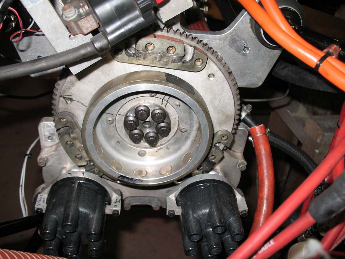
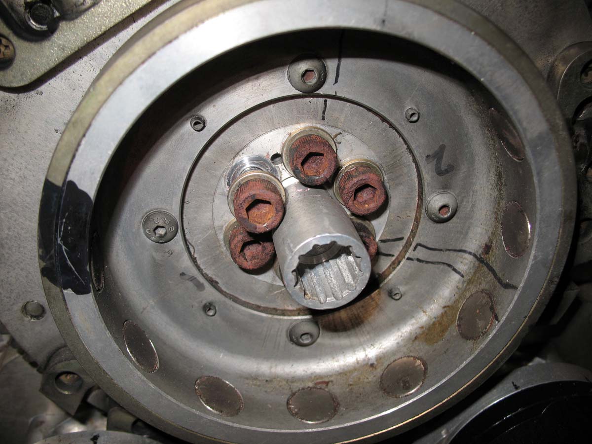
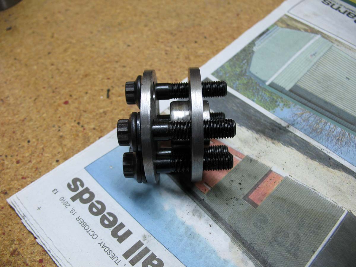
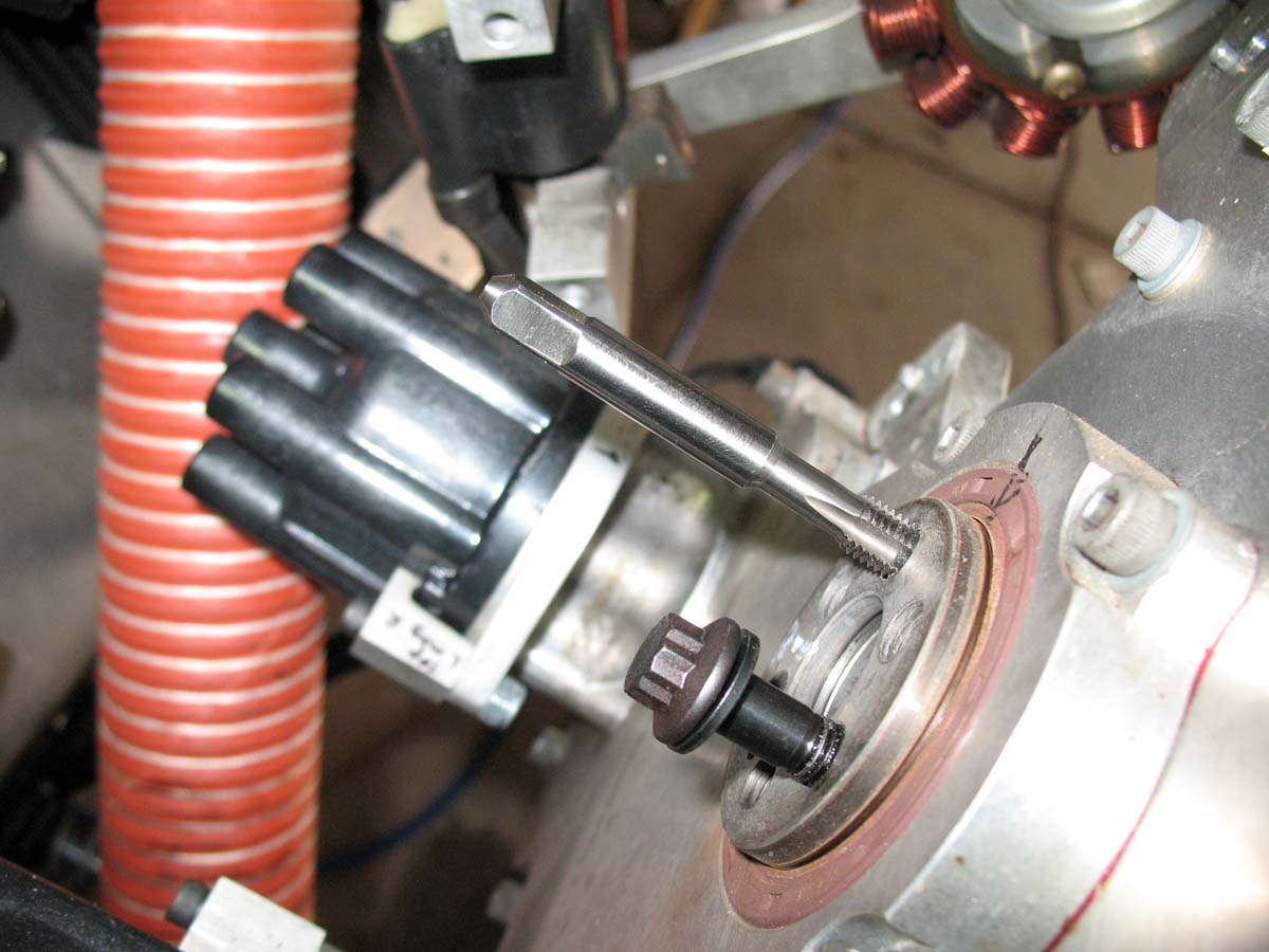
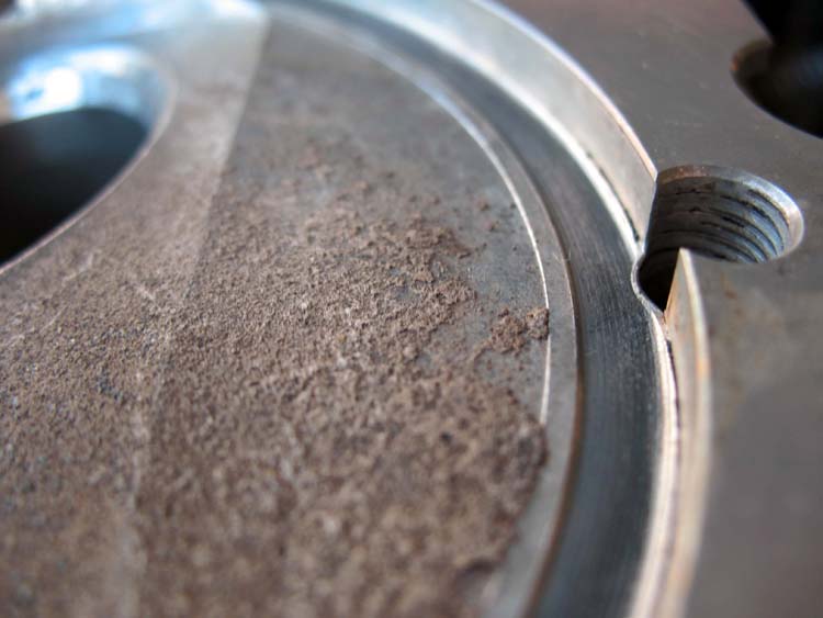
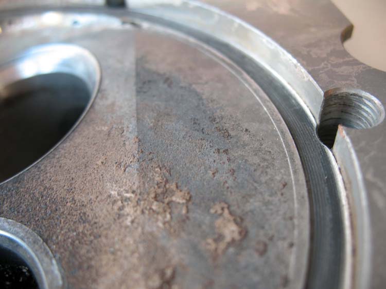
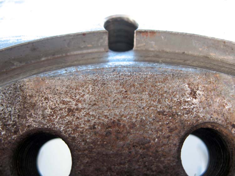
I've asked plenty of questions of late, and added little. Thanks for the helpful comments from members of this board. All have been very helpful in the top end rebuild process I am now near completing. I thought I'd post a few photos of the flywheel spacer modification I have used. In short, my assessment is that flywheel bolts break because the 'friction joint' between the crankshaft, the ali spacer and ali 'flywheel' gets loose and the bolts subsequently get stressed and break. Maintain the friction between the parts by maintaining bolt preload and the problem is solved. Dowels won't stop this from happening. The new steel centred 'starfish' flywheel on newer engines removes the relatively soft aluminium centre which the flywheel bolts tended to recess into, losing their preload and loosening the sandwiched parts. Old flywheel centre is pictured below with Unbrako 5/16" 1-1/4" long cap screws tighened up against the ali flywheel. Two were loose, and all were recessed into the flywheel by up to 0.3mm. I machined up a steel replacement spacer, but dispensed with the vacuum drive extension. I also machined a 4.5mm steel disc, and replaced the bolts with ARP brand 5/16" 1-1/2" long bolt (to counter the new compression disc and provide a few more threads into the crankshaft). The crank bolt holes were cleaned out and checked for adequate depth. Replacement steel spacer with compression disc and new bolts The aluminium flywheel is now sandwiched between two steel discs. The bolts are spec'ed to to tightened up to 50+ft/lbs into steel. We settled on 45ft/lb as a compromise figure. With the vacuum pump drive no longer sitting in the hole in the alternator spider, I can use a mirror to check the witness paint on the bolt heads during regular inspections. This idea was developed by a local Jab owner who generously spent many hours with me going through the rationale for why these bolts break and how he thought one could prevent it - basically get rid of most of the soft aluminium in the sandwich of parts. We'll see how things go... Greg v

-
Have you noted your EGT's to be higher than those specified in the Jab manual, being closer than the 100mm (or 120mm, depending on which manual you look at) specified by Jabiru? Greg v
-
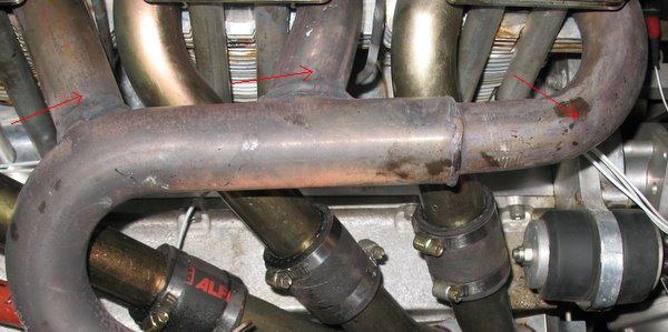
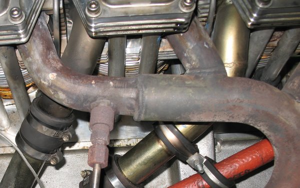
Hi all I'm sure this has been covered somewhere at some time in the past, so apologies for repetition. I'm nearing the end of a top end overhaul of my solid lifter 3300 (#391) at 400 hr TTIS. Problem appears to be chronic overheating, evidenced by primarily by cylinder head recession on the exhaust side of all heads and stuck rings in all cylinders at tear down due to excessive burnt oil deposits. I am installing better monitoring (6 cyl CHT monitor is going in this weekend) and am undecided on EGT. Currently I have one EGT probe as installed by the builders in pipe for number 6 only. I would like to add at least one more on the left, but it seems to me putting it further down the pipe where a mixture of all 3 cylinders is seen would be better. I'd obviously have to shift the right side to match to make it useful. My question relates to a 6 cylinder EGT monitoring solution. How close can they go to the exhaust outlet? Obviously closer = hotter. Anyone installed 6 cyl EGT monitoring on this style of exhaust pipe? I'll have to recheck the measurements but from memory I would only be able to get 50mm away from the exhaust flange on all 6 before hitting the common part of the pipe. Also any comments on EGT probe type? I was considering this as a easy solution (http://www.aerospacelogic.com/store/index.php?dispatch=products.view&product_id=75) as it all comes in a box and if I install it carefully, at least the measurements will be somewhat internally consistent. Any issues with the clmap type EGT probes compared to the welded on type that is currently fitted to my number 6 pipe (in photo below)?
-
I ordered a new set of throughbolts from the factory 4 weeks ago. They arrived with the new 12 point nuts (ARP) and throughbolts with slightly longer threads than the ones I am changing out that should give a 1-2 threads at each end. The new overhaul manual does say that you can use the ARP nuts on the old throughbolts though. Greg v
-
Thanks Ralph. The factory now provides ARP nuts as standard with new throughbolts, and they have a smaller diameter, hopefully avoiding the cylinder distortion caused by larger diameter nuts. I have new ones here ready to go in. Stan Hyde at Feilding reportedly had two lots of through bolts supplied with undersized threads that stripped when torqued up, so replaced those throughbolts with ARP units, though they would have been metric, I think there was some machining involved. Greg v
-
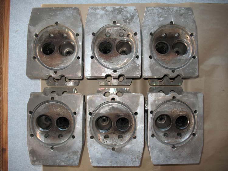
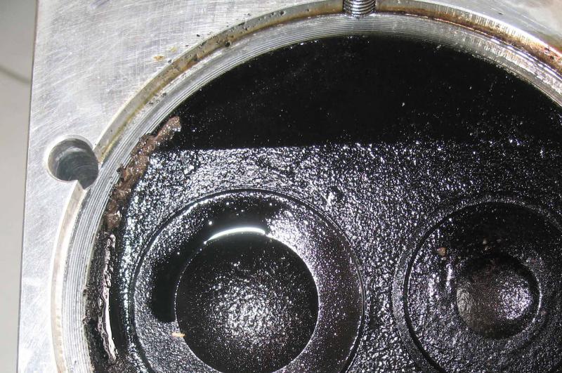
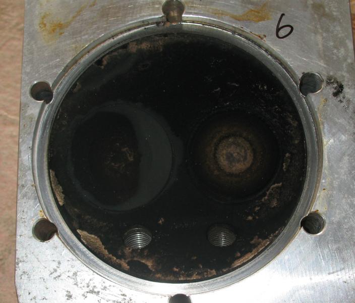
As promised, some more images as things slowly progress. I guess the question comes down to this - with the cylinder head crush at the level in the photos below, what would be the potential issues with honing the cylinders, replacing rings and valves, and putting the thing back together? It seems clear I need to get my temps down given the amount of carbon / oil residue that bound the rings up, so looking at 6 cyl CHT monitoring as a minimum. My temps have been CHT max at climbout 280°F, usually 265-70°F cyls 5 and 6. EGT at factory position right exhaust manifold 670-690°F cruise, 620-630°F at wide open throttle, oil temps between 70-95°C depending on outside air temp. Thanks again for the helpful comments so far. [ATTACH]13235.vB[/ATTACH] [ATTACH]13232.vB[/ATTACH] Cylinder 1 exhaust side [ATTACH]13234.vB[/ATTACH] Cylinder 6 plug side [ATTACH]13233.vB[/ATTACH] Cylinder 6 exhaust side
-
Thanks for the helpful advice so far. I'll try and attach some photos from disassembly of the heads hopefully showing the problem area- I'll take some better images when I get the heads back later this week. Connection is patchy what with the earthquake today...and that was just in Wellington Airport! Who knew Christchurch Information directed all jet traffic in NZ... Jabiru Engine support have emailed telling me there is no Leeb hardness number available for the aluminium heads used in my engine. Moot point really - the cylinder has crushed the heads so they are too soft for whatever torque I had them at (24ftlb cold, but maybe I need to calibrate the torque wrench again!) [ATTACH]13180.vB[/ATTACH] [ATTACH]13179.vB[/ATTACH] Greg v
-
My 3300 (33A-391 - 402 hr TTIS) started throwing excessive amounts of oil out the breather recently, so out with the leak down tester (thanks for all the helpful tips from forum members on getting this right) to discover a significant drop in cyl 5 compared to 4 months ago. Broken second compression ring found stuck in its groove in cylinder 5, with mild barrel scoring and a bronze coloured piston skirt presumably from excessive blow by. On inspection, every other cylinder also had at least one stuck ring (no others broken), with plenty of hard carbon deposits in the ring grooves. The engine is in a J200 airframe (#60) with standard air ducts and gull wing deflectors in between cylinders. Assuming the rings stuck primarily because of overheating, it looks like I'll need to do some work to increase airflow to the heads. CHTs on #6 and #5 (the only two I monitor) were generally running around 280°F or less (measured between the sparkplug washer and head). Less than manual limits, but too high for engine top end longevity it seems. I sent my cylinders away for check of wear limits and a hone as per the manual specs, and the guy doing the job has noted that 'the cylinders seem to be working themselves into the aluminium head'. He has asked for the Leeb hardness number for the heads, which I have duly asked the factory for. Is this what I have seen mentioned before as head crush? Is this common in 3300 engines? I have to admit I didn't notice this on disassembly but then I wasn't looking for it either. Head bolts were checked at 24ft/lbs cold at oil change, though I guess they could have been tighter and I wouldn't have known. Any comments or previous experiences with this would be gratefully received. I'll get some photos up, and post how things turn out. Anyone know whether there is an acceptable wear limit with respect to this? Greg v
-
New Zealand CAA AD for Jab 2200/3300 engines This is the AD released today by NZ CAA giving 5/16" flywheel attachment screws in the 2200/3300 a 500 hour finite life. Apologies if this has been posted elsewhere. Greg v JABENG.pdf JABENG.pdf JABENG.pdf
-
Good point, and thanks!
-
Hi all. Complete newbie question here, but what have others found to be the best method to immobilise the prop on a 3300 when performing a leak down test? Was always easy on a motorcycle - sticking it in gear with the rear brake on! Any suggestions / experiences / sage advice gratefully received. Greg v Northland, NZ.