

gwillimm
-
Posts
62 -
Joined
-
Last visited
Content Type
Profiles
Forums
Gallery
Downloads
Blogs
Events
Store
Aircraft
Resources
Tutorials
Articles
Classifieds
Movies
Books
Community Map
Quizzes
Posts posted by gwillimm
-
-
Dose any one know what air field top gear used tonight.
Thanks Mick :confused:
-
well done
Well done fly girl:clap:

-
Humm
Well when the Jabiru engine shop told me the thrust is taken from the propelor flange on a areo plane not the flywheel as a car they lost me,
I agree
The ONLY thing to consider would be the direction of rotation. Which end of the engine you take the drive from is irrelevant.
The way the offset works is to cause the piston to 'rock", because of the pressure acting on the crown. The piston wants to rotate on the piston pin axis. This puts the top part of the skirt against one side of the cylinder wall and the bottom part against the opposite side, and helps to eliminate the "clack" when the piston moves over TDC, under load.
From Nev
Thank you
Legally you should assemble your enging in accordance to the Jabiru manual.
Yours in flying
Mick:rotary:
-
Welcome From Cowra
Welcome aboard.Good to see some locals flying around.
Yours in flying
Mick
-
PPL test
Gooday Tomo I converted to GA about 3 years ago PPl test not to hard but Meteorolgy bit was confuesing. Anyway best of luck don't let the flying school bleed you to much. It should be about 6 hour converition .:thumb_up:
Funny I do about 4hours GA and 250 hours RAA per year. The training was good but sick of CASSA and there Parasite fees.
Yours in flying
Mick
-
Jab CHT from manal
Hopes this helps.
Yours in flying
Mick
Run in Period
Oil 80 100 120
Outside Air Temp -17oC to 25oC 15oC to 35oC Above 35oC
(1o to 77oF) (59o to 95oF) (Above 95oF)
Normal Operations
Oil W80 W100 W120
Outside Air Temp -17oC to 25oC 15oC to 35oC Above 35oC
(1o to 77of) (59o to 95oF) (Above 95oF)
2.6 Cooling System
Free air cooled. Ensure that baffles are correctly fitted & located.
The required pressure drop across the cylinders at 1.3 Vs in take off configuration is 4.3 cm (1.7") water gauge, minimum.
2.7 Operating Speeds and Limits
Maximum continuous speed 2750 RPM
Maximum 3300 RPM ISO STD Conditions
Idle Speed: 650 RPM
Oil Pressure: Normal Operations Min 220 kPa (31 psi)
Max 525 kPa (76 psi)
Idle Min 80 kPa (11 psi)
Starting & Warm up Max 525 kPa (76 psi)
Oil Temperature: Min. 15 oC (59oF)
Max. 118 oC (244of)
Continuous Temperature: 80 - 100 oC (176o - 212oF)
Max. Cylinder Head Temperature: 175 oC (348oF)
(reading on the sensor spot
of the hottest cylinder)
Continuous 150oC (302o F) Max.
-
Motor running well
Gooday all after a lot of research us and other LAME when you draw up the cranckshaft, direction the pistion offset we fitted the pistions with the notch to the rear.
Thanks for all your feedback. :hittinghead:
Yours in flying
Mick:rotary:
Look at the pistion direction humm
Contrails ! Inside a Jabiru
Photo Pete Krotje
Anatomy of the Jabiru 3300
Jabiru engine lovers will enjoy this little "journey inside a Jabiru".
Those Jabiru 3300 and 2200 pictures were provided to Contrails by Pete Krotje from Jabiru USA Sport Aircraft, and Jabiru owners, and are published here with their kind permission.
The 4-cylinder Jabiru 2200 technology is quite similar to that of the 3300.
Jabiru 3300 6 cylinder tear down
Bottom end
Note how the engine is secured vertically on the bench with two bolts through the propeller flange. The Loctite 515 tube is for sealing the crankcase.
Near the top, the mechanical fuel pump pushrod protrudes from the crankcase.
Further down are the pushrod holes and and oil orifices to cylinder heads.
At the bottom is the oblique oil pump pickup tube with its skewed end.
The fully machined crankcase splits vertically.
At the top of the camshaft, in front of the #6 piston, the fuel pump eccentric and its pushrod passes through the right crankcase half.
This model has solid lifters. The oil return holes machined in each lifter housing are clearly visible.
The top cylinder has one of the through-bolts holding the crankcase half and the cylinder base flange.
At the bottom is the oil filter adaptor with its thread and the oil pressure relief valve nose, washer and retaining ring.
The main oil gallery runs down the length of the left crankcase half at the level of the cylinder head lubricating holes.
Crankcase
Matching crankcase halves are fully machined from solid light alloy. The machining is fine.
A serial number can be made out in the #1 piston passage in the right crankcase half. See also the oblique oil pickup tube.
The crankcase has 7 bearings. The #1 bearing shows the recessed thrust bearing washer housing. Note the positioning dowel at each through-bolt passage. Sealing is with O-rings in grooves machined in the dowel bores.
Note the waisted through-bolts (10 long, 4 short, 2 very short), and the intricate oil passages to the main bearings.
Looking closely at the lifter housings, the pressure lubrication holes and oil return holes are visible.
The camshaft bearings seem to be splash lubricated.
Moving parts
Camshaft
The camshaft installed in the left crankcase half.
The 7 journals and 6 pairs of cams are clearly visible.
At the rear near the timing pinion, the fuel pump eccentric is located between the two #6 cylinder cams.
Also note the two thrust bearings machined in the camshaft near the pinion.
Crankshaft
The hollow crankshaft is machined out of solid 4140 chrome molybdenum alloy steel. It features 7 main bearings (48 mm diameter). There is a double bearing for the propeller.
The steel shell bearings are of automobile type. The generous oil holes in the crank pins and main bearings are visible.
Lubrication of the big ends is ensured by oblique channels drilled from main bearings # 2, 4, 5, 7, the bearing shells of which have a groove and hole. The #1 bearing shells have no hole, as the oil is fed via the hollow crankshaft main bearing.
The crankshaft seems very light and its finish is outstanding.
Hollow 45 mm diameter crank pins have plugs closing the oil circuit.
Thrust faces are machined at the front of the crankshaft and the front face of the #1 crank throw. They bear on thrust bearings housed in recesses in the crankcase.
Each crankshaft end takes a lip seal. Those seals are removable without splitting the engine.
The propeller flange is removable to give access to the front crankshaft seal.
Pistons
The slipper type pistons come from General Motors Australia.
The very short pin is floating and maintained by circlips in re-machined grooves in the bosses.
The classical 3-ring set includes two cast iron top rings and one expander-type scraper.
Note how the piston passages in the block are narrow, ensuring better crankcase rigidity.
Connecting rods
The I-section connecting rods are machined from 4130 alloy steel.
The big end caps are tapped for 1×5/16 UNF screws, so disassembly implies removing the pistons and splitting the crankcase.
Matching big end caps are positioned with two 3×14 dowels [1].
The steel shell bearings [2] (45 mm diameter) are of automobile origin.
Top end
Cylinder heads
The heads are machined from solid aluminium alloy.
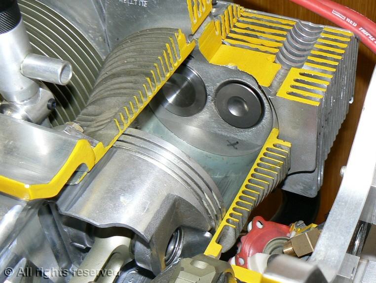
The combustion chambers are wedge shaped, with the spark plugs located on the thick side.
Note the squish surface (see below) with an "X" mark.
The wedge shape gives a very compact combustion chamber.
This arrangement results in parallel valves, with inlet and exhaust ports on the same side.
The head shown here is from a Jabiru 2200 4-cylinder engine.
The different diameters of the shrunk in seats are visible : smaller exhaust on the left, larger inlet on the right.
One can clearly see the turbulence generating squish surfaces below the spark plug holes and above the ports.
Please note that the finning is larger on the exhaust side, as thermodynamics dictates.
Valve gear
The picture shows the valve gear components.
The parts are the same as in the Jabiru 3300 6 cylinder engine.
Below the head are the valves with their single coil spring (40 mm long), spring seat washer, spring retainer and split collets.
In the forefront are the two manually adjustable rockers (solid lifters) and their 12 shaft.
Rocker pushrods are visible on each side.
Valves and guides
The valves are manufactured in England for Jabiru.
Stem diameter is 7 mm, and head diameters are 33 mm exhaust, 41 mm inlet.
The original valve guides are manufactured from aluminium/bronze, and have an oil hole.
Maximal allowable valve/guide tolerances : inlet 0.10 mm , exhaust 0.12 mm.
Timing gear and accessories
Rear engine plate
The rear plate is machined from a light alloy plate. We can make out the trace of the timing gear housing, sealed with Loctite 515, as well as its two positioning dowels.
On the crankshaft end, the 6 tapped holes for the flywheel screws, and the small bore of the pinion indexing pin.
In the forefront, the large 44 tooth camshaft gear, the thinner pinion above is the distributor drive gear (30 teeth).
Near the s/n two timing marks are showing in white.
In the corners, the 4 silent blocks mounting lugs are integral with the rear plate, which also shows the starter motor aperture.
Timing gear
The gear housing is machined from a light alloy plate. The timing gear lip seal (50×65×8) is pink.
In front of the seal, the 22 tooth timing gear which slips onto the crankshaft end. We can see the 6 screw holes, and the 3 6×24 dowel bores, as well as the indexing pin maintaining the pinion on the crankshaft during assembly.
On each side on the housing, the two pinions (30 teeth) are riveted to the distributor shafts. Behind are the distributor cap mount plates, the left one showing its lip seal (15×24×7).
Flywheel
The flywheel has 3 assemblies of 3 15×7 rare earth magnets and pole plates, as the the engine has 6 cylinders (engines fires 3 times per revolution) .
In the middle, the alternator rotor has 12 cylindrical magnets, which have attracted some screws.
The internally splined part is the light alloy vacuum pump drive.
Alternator
The spider stator mount standing on its 4 L-shaped mount blocks.
The black sleeve coming out of the spider protects the alternator leads.
12 pole stator on its spider mount. The two ignition coils are screwed to the 4 L-blocks through their pole plates.
Induction manifold
The 6 lower induction pipes are inserted into a fully machined two part plenum.
The manifold assembly is attached under the sump at the rear of the engine.
The rubber carburetor coupling is visible on the right.
-
flying is a addition
Gooday Dave
Well you got the addition. It just gets worse.
Our club had a open day at Cowra on Sunday Humm, did about 4 hours flying, bit flown out at the moment.
Took up one of our members and flew to his place at Greenforpe and landed on his property in a paddock, then flew around the area and back to Cowra. Then a nother member for practice, and a new member who hadn't flown a Brumby before.
At the end of the day flew out to a mates place near Orange to catch up, intresting strip to land on, up hill and pritty routh. then flew home.
But it was a good day, Weather CAVIC
Yours in flying
Mick
-
Well done,
Learning has just started.
Yours in flying
Mick
-
Good on ya flygirl it just gets better.
Yours in flying Mick
-
'Stakes
Catch 20 rabbit skin into fillits die the meat red over night.
Invite friends around for free meal.
Drink heaps of grog.
Friend won't no the difference.
If they say the meats tough blame the butcher.
Love the rock
Mick
-
curcuts curcuys curcuts
Gooday Dave you can never get enouth! humm. You will get to the stage when you will breeze it on every time, how cool. Remember a good curcut is a good landing.
What are your down wind checks?
Are you in the 160 or the 230 jab?
Have you joined the flying group?
Email me when you have a open day and i will come over for a fly.:thumb_up:
Yours in flying
Mick:rotary:
-
The weight of the BRS is included in the MTOW of the aircraft.
You need to recalculate the weight & balance of the aircraft once fitted.
Depends on the brand but the weight is about 15 kg's.
Mick
-
X wind landings
Gooday Dave good to see you flying.
Cross wind landings are cool, lf I have the option i will land x wind, its good practise.
One of the secrets of flying is "you fly the plane" don't let the plane fly you.
If its not doing what you want to fix it.
Are you in the Bathurst flying club?
All the best with your learning
:thumb_up:Mick
-
Just flying
Ha Dave good to see you into curcuts, remember a square curcut gives you a good landing. One day it will just click and you wonder why it took so long to get it wright.
All the Best,
love the flying.
Mick
-
First solo
Ha love learning i have never forgotten my first solo in a jabiru j2 about 8nm fron the' stip 'engine fail ' hum' got it down in a paddock ok,
never for got whot my instructor saidAviate, Navagate and don't call a maday its too much paperwork.
Humm it was years ago.
He is not instructing any more.
probly good thing.
Always expect the unexpected
Mick :smooch::smooch::smooch:
-
Gooday all i am in the prosess of top end over hall on my jab 3300 humm.
I have a question ?
Jabiru use a holden piston, the holden motor rotates in the clockwise direction the jabiru rotates in a anty clockwise, thus should mean on a Jabiru the pistion notch on the piston crown should be fitted to the rear.
,
Offset is always to the major thrust side of the piston, as the Jabiru motor rotates the oppsite direction the pistion notch should face the rear. 'Not the front' as stated in the manual.
Quote' from Jabiru manual
Note: Arrows on inside of pistons point in direction of rotation. Oil Rings and
pistons and bore well. Notch on the piston crown faces the Propeller Flange.
When i arsked Jabiru engine shop they told me in short that the thrust is from the propeller on a plane and a car it is from the flywheel and according to them the manal is correct.
I for the thrust is from the power stroke ???
"humm" :hittinghead: I dissagree.
All the reserch i can find states that,
"Most engines today utilize pistons with an offset pin bore. That is, the pin
bore is "moved" a specific distance from the centerline of the piston. In gas
engines the offset is always to the major thrust side of the piston. The
piston thrust side is the part of the piston perpendicular to the pin bore
that carries the majority of side loading during the power stroke.
The primary reason for pin offset is to prevent the piston from slamming into
the cylinder bore after the connecting rod journal passes top dead center.
This problem is referred to as piston slap. The desired scenario for piston
movement is to gently rock from side to side within the bore. This rocking
motion eliminates slap. "
by Hunter Betts
Can any one else shed some light on this
Thanks Mick
-
Corvair
Gooday John there is a bloke in Victoria who is running the Corvir enging in a aircraft and he is quite knowledgeable. I will forward his email address and he should be able to help you.
Happy Flying
Mick
-
Love learning
Gooday Dave
Gee good weather we have had this week. Have you been flying?
Hows the flying going?
Dose your instructor give you home work?
Its realy good to prepare for the lesson this will help with learning, ask what your going to do next lesson then study for it.
How many hours have you logged up?
Its realy good to her how you are going.
Thanks Mick
-
Training how cool
Gooday Dave
God I enjoy the learning and gess what you never stop learning. yep how cool.
Tell us about your preflight what do you check?
How do you find your instructor?
What do you like about the jab?
Which theory books do you use?
Are you having trouble with anything?
You can get a lot of infomation from this forums there are heaps of people who can help.
Yours in flying
Mick:clap:
-
Welcome
Welcome good to see more people from Central west on board.
What do what do you fly
Catch you round in the air.
Mick
-
Still getting infomation
Thanks every body for your replies But is there some one out there who has the rotec system fitted to there plane and are you happy with it.:hittinghead:
Thanks Mick
-
Gooday
Gooday Dave
Its good to see more people learning to fly, the only problem is the addiction 'humm'
Good see you learning at Bathurst, what a good part of the world.
let us now how the training is going.
Yours in flying
Mick
-
planes Planes planes
Gooday lexman
If your going to travel around AUS perhaps a J200 Jabiru, heeps of room in the rear for gear and still in wait envalope, good cruse speed 120 kts '2 miles a minut'. Good all round aeroplane. Aus made big plus.
That would be my secand choice of planes. :thumb_up:
Why do you want folding wings? What ever you decide make shore you hire one or find somewone with one and go on a trip before you buy one.
A test flight is not enouth time.
Have you started flying yet:rotary:
Bathurst or Orange is a good place to learn they Both have RPT. And there training area is close by.
Catch up soon
Mick


 Welcome aboard.


 :thumb_up:


Hello fellow aviators
in Just Landed - Welcome
Posted
Welcome
Gooday Douglas

Welcome ,,, love the spitty can you tell us more about it and some photos inside and out please.
Yours in flying
Mick