

Ross
-
Posts
729 -
Joined
-
Last visited
Content Type
Profiles
Forums
Gallery
Downloads
Blogs
Events
Store
Aircraft
Resources
Tutorials
Articles
Classifieds
Movies
Books
Community Map
Quizzes
Posts posted by Ross
-
-
J170 vs J160
According to the POH, what is the Stall speed of each aircraft with full flaps deployed?
Regards
-
Engines
I suspect you are unlikely to get an answer to your question about a Jabiru motor without quoting the full engine number, whether mechanical or hydraulic tappets, whether it has been factory overhauled and if so what replacements for wear have been done and what upgrades if any have been fitted.
Is service history of the engine available?
How did it do the first 500 hours??
A bloke I know actually admitted running his motor for a kit plane without a prop or cowls in his garage for a few minutes!!
I would not comment, but those are some of the questions I would need to know to get an opinion from more experienced people than I am.
Regards
-
Thermocouples
It was many years ago, about 40, in the Instrument section of the Combustion department at Australian Iron & Steel Pty. Ltd. (BHP) at Port Kembla during my brief experience in that department with little experience under the direction of experienced Instrument Fitters that we made thermocouples used around the various production furnaces such as coke ovens, ingot reheating, slab reheating, blast furnaces, open hearth furnaces etc if I remember correctly. The actual very high temperatures inside the melting furnaces such as the open hearth furnace were more difficult being measured by focusing the radiation rather than the hot gases or molten steel from inside the furnace up a tube and onto a number of small thermocouples in a circle arranged in series I think to produce a bigger voltage which was compared against a standard voltage produced by a special long life battery in the instrument.
We used two wires, something like a bare inch or a bit less of each was twisted together then heated with an oxy acetylene torch until the end of the pair melted together in a small ball on the end of the pair. The size of the ball did not seem to be critical. The two wires were of Iron Constantan and Platinum after 40 years memory ago?? Platinum is worth more than Gold.
Gold about $A1,219/ounce,
Platinum is about $US1,600/ounce or over $US 57 million/ton
Nowadays there are plenty of suppliers with thermocouples made up to suit a multiplicity of uses and range of temperatures and instruments to go with them. The instrument is really a special sensitive voltmeter calibrated in degrees C or F.
There is plenty of information on the internet on the subject of thermocouples i.e. two dissimilar metal wires welded together exposed to continuous heat produces an electric voltage or current related to the temperature of the junction. There are various combinations of wire types types suited to different temperature ranges also they can be insulated with ceramics to be inserted into a metal hole in for example a carburetor body to check on icing or used bare in exhaust flues or cylinder heads.
The carburetor, CHT and EGT in our RAAus aero engines are well within the range of simple thermocouples.
See the following site for an introduction.
There are probably many small firms and large ones involved in these types of instruments in Australia.
Thermocouple - Wikipedia, the free encyclopedia
I am not an expert, in fact not even up to date on what is available.
Regards
-
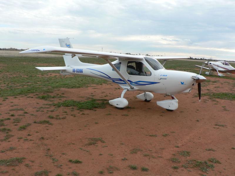
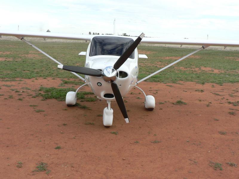
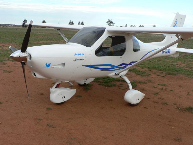
I had a close look at a very nice J160 with 3300 ccs sitting up the front visiting Leeton's Brobenah airstrip last year at a fly in for a couple of days.when will they put the 6 cyl motor in the J170???I have a number photos if you are interested but not under the bonnet.
Rod Stiff told me in a personal phone call a few years ago that the 2200 and 3300 motors share the same engine mount.
If I remember correctly what was said by the pilot owner builder, it required a bit of restraint on the amount of throttle used on takeoff otherwise it tended to be rather vertical!

Does it have standard J160 wings-I do not know. I would expect that it would have reduced fuel, luggage, passenger carrying capacity to be legal.
-
A local friend is building a Sonex kit which comes with a very nice looking fuel tank;
some kind of plastic fuel tank moulded into a complex shape which looks very rugged, not fibre-glass.
I have no information on it but it looks very good - the material might be worth researching.
Regards
-
 1
1
-
-
In relation to air locks in fuel lines the smaller diameter fuel lines are more likely to carry air bubbles along the line rather than allowing an air bubble to rise back to the tank in a sloping or vertical line due to the bigger effect of the meniscus in a smaller bore hose or pipe.
You can see this effect in clear tubes by standing a few short lengths of them on end each of different sized diameters in a dish of fuel.
The fuel will rise up the smallest diameter tube the longest distance - this will be the tube size that gives the most problems with air locks.
The bad effects of friction and meniscus rapidly reduce once you get to about 1/4 inch diameter tubing or larger with petrol.
-
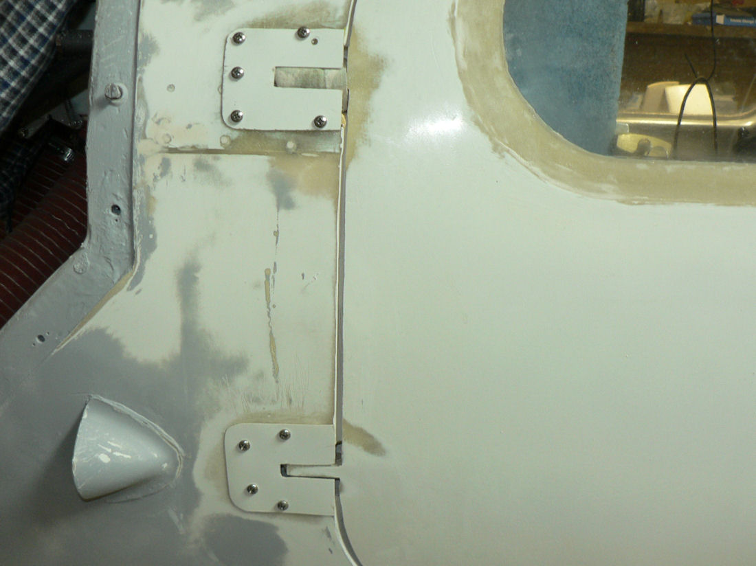
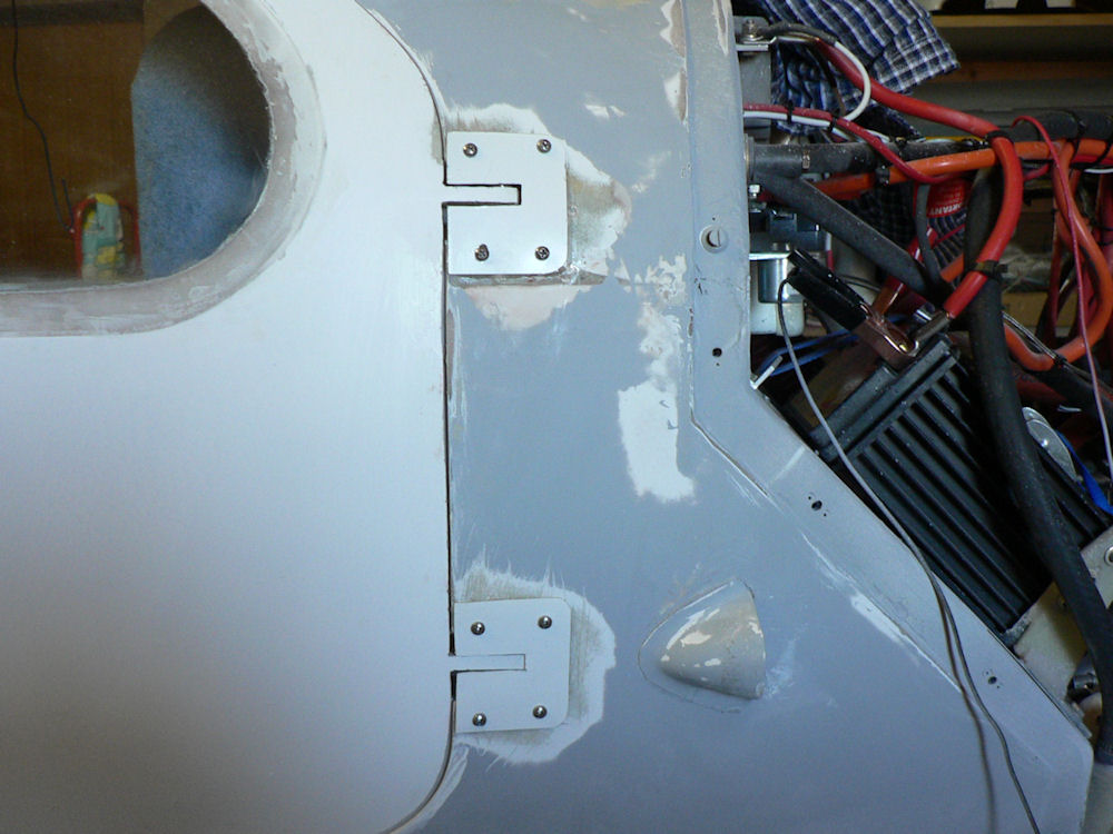
20091104 Cover fuselage door hinge recesses old style door hinges
Trimmed off existing wide cover off back of door hinges brackets as it needs an excessively sized space to clear the fuselage in the fuselage hinge recess.
Cut out four new covers from spare material to blank out the hinge recesses.
Cut slots in the covers to suit the thickness of the door hinge brackets.
With the doors in place, fitted slotted cut out covers with self tappers while checking clearance by swinging the doors.
Due to sloppy hinge pins & holes, large clearance was needed to allow for door hinge bracket clearance in the slot.
Once clearance is OK sanded fuselage in hinge area back to fiberglass - cleaned up sanded area of fuselage & new covers with acetone.
[ATTACH]9049.vB[/ATTACH][ATTACH]9050.vB[/ATTACH]
Applied "5 minute Araldite" to new covers and matching positions on fuselage, fixed with self tappers.
Checked door clearance as each cover is done.
Wiped off excess araldite with acetone rag.
Allowing to cure
Once the araldite has cured the self tappers will be removed, the holes filled, and fill applied around the covers to smooth them up.
With these external covers over the hinge recesses it should be easier to reduce air flow into the cabin.
-
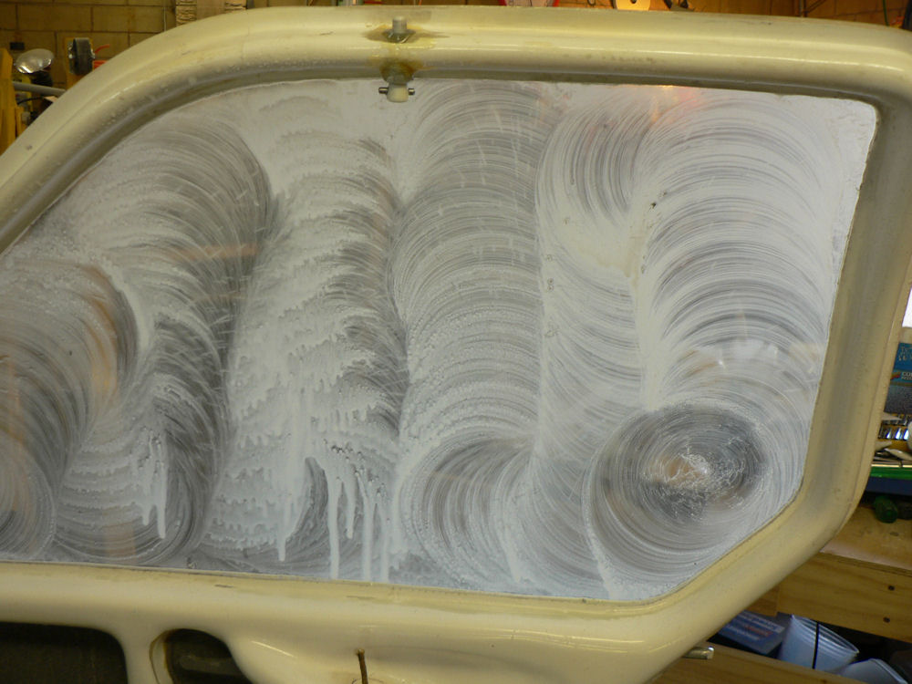
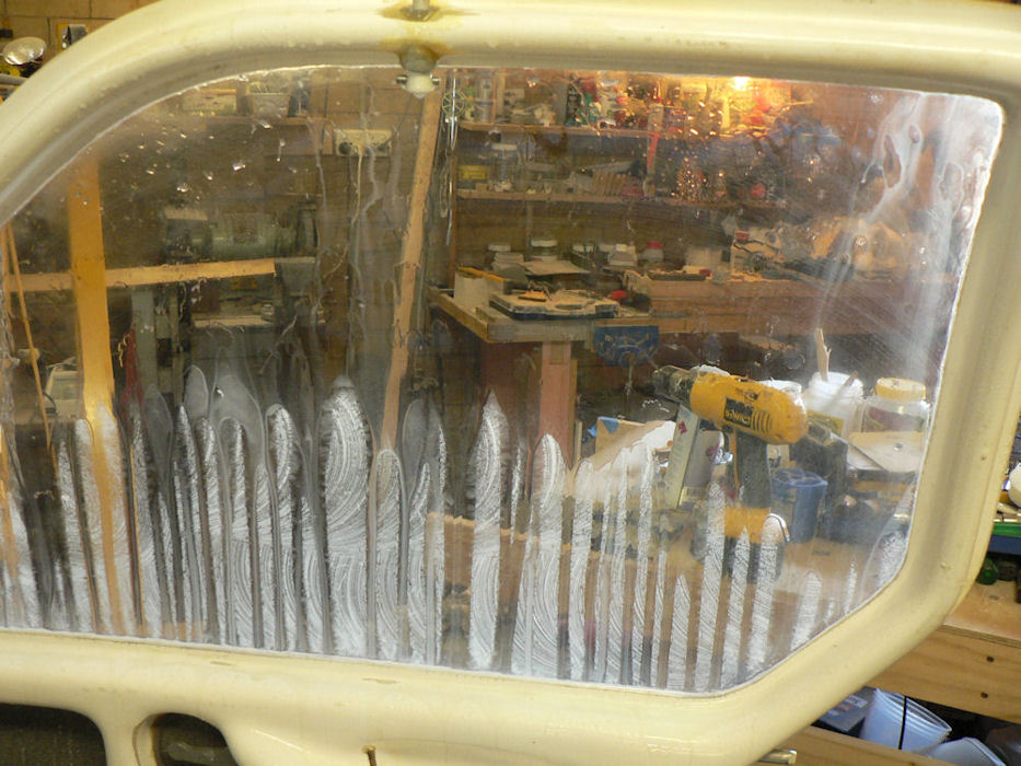
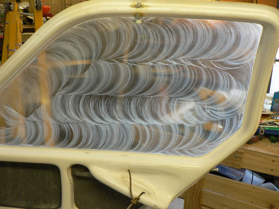
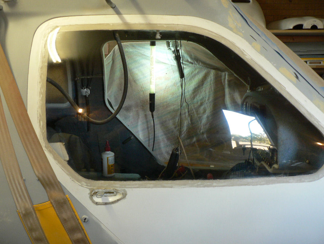
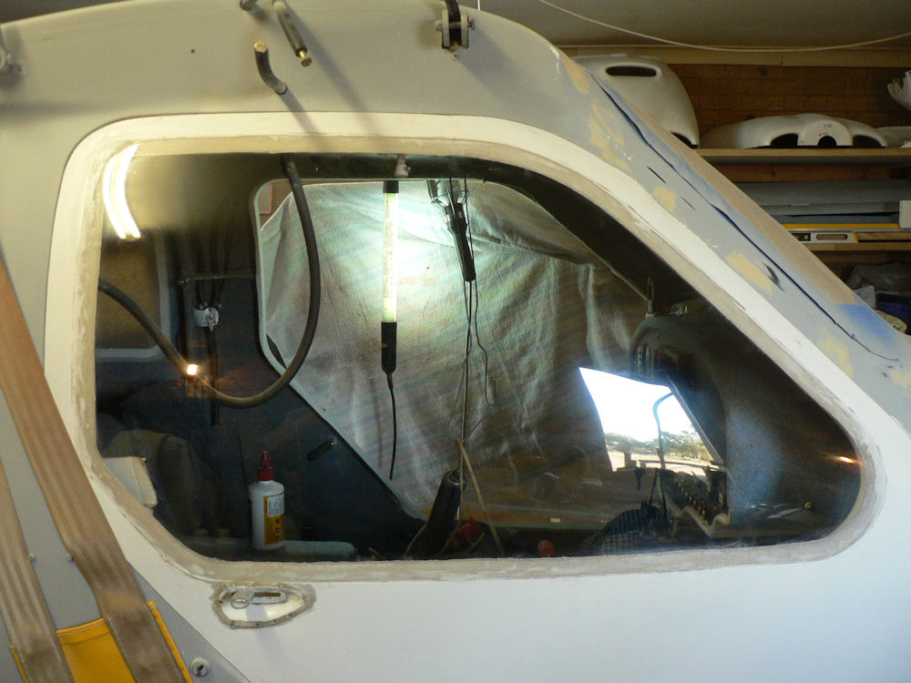
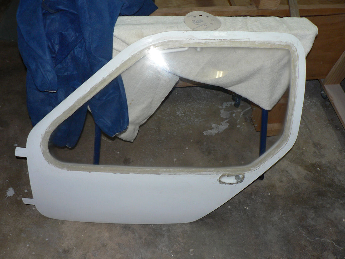
20091020 Door window polish (starboard door)
The starboard door was temporarily mounted on the fuselage to facilitate handling & inspection during the window polish.
The door was tied so that it could be opened & pushed in the polishing process w/o damaging the hinges.
Both sides of the starboard door window was polished as done for the port door window.
The photos from inside show a couple of the stages,
first one is after the first liquid polish,
second one half way through a wash and clean up between polishes,
the third one is final polish on the inside of the window.
[ATTACH]8928.vB[/ATTACH][ATTACH]8929.vB[/ATTACH][ATTACH]8930.vB[/ATTACH][ATTACH]8931.vB[/ATTACH]
[ATTACH]8932.vB[/ATTACH][ATTACH]8933.vB[/ATTACH][ATTACH]8934.vB[/ATTACH][ATTACH]8935.vB[/ATTACH]
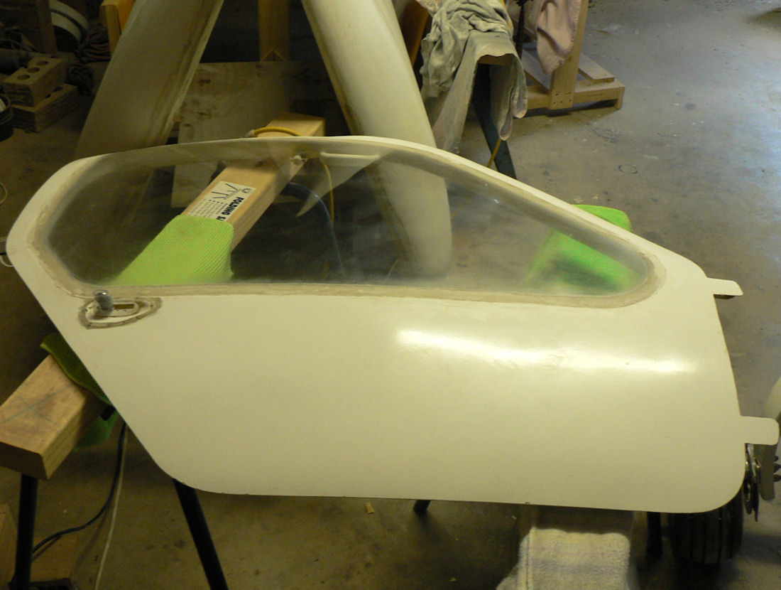
The rest are some shots after some of the polish passes on the outside of the window.
The reflection of the open outside garage door behind me in the bottom right hand side of the last five photos is gradually getting less of a halo around it as the polish on the window is getting better.
-
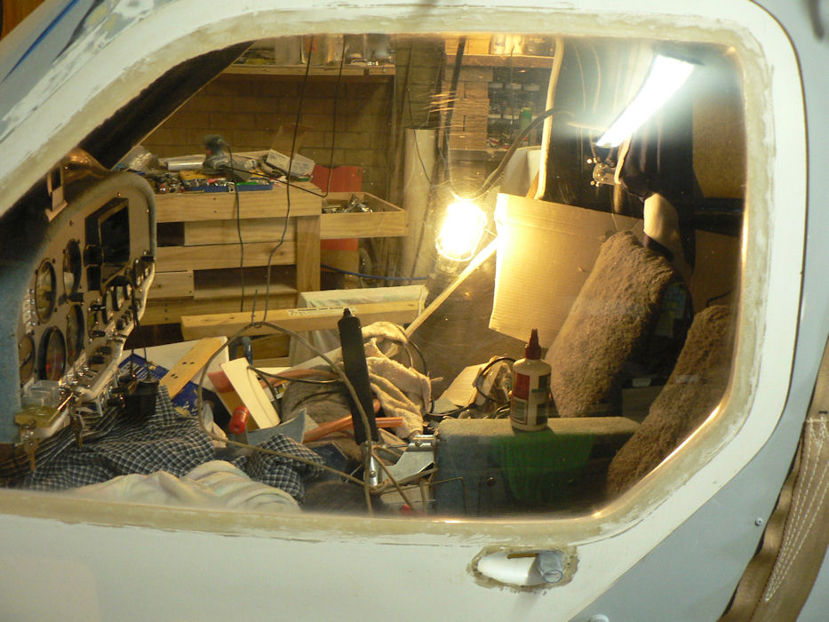
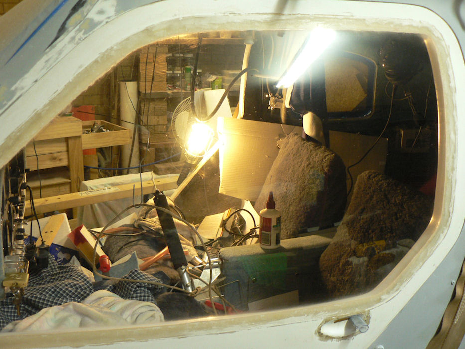
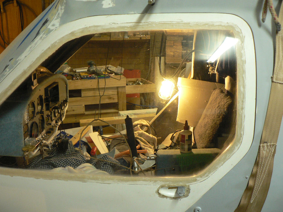
20091019 Door windows Polish
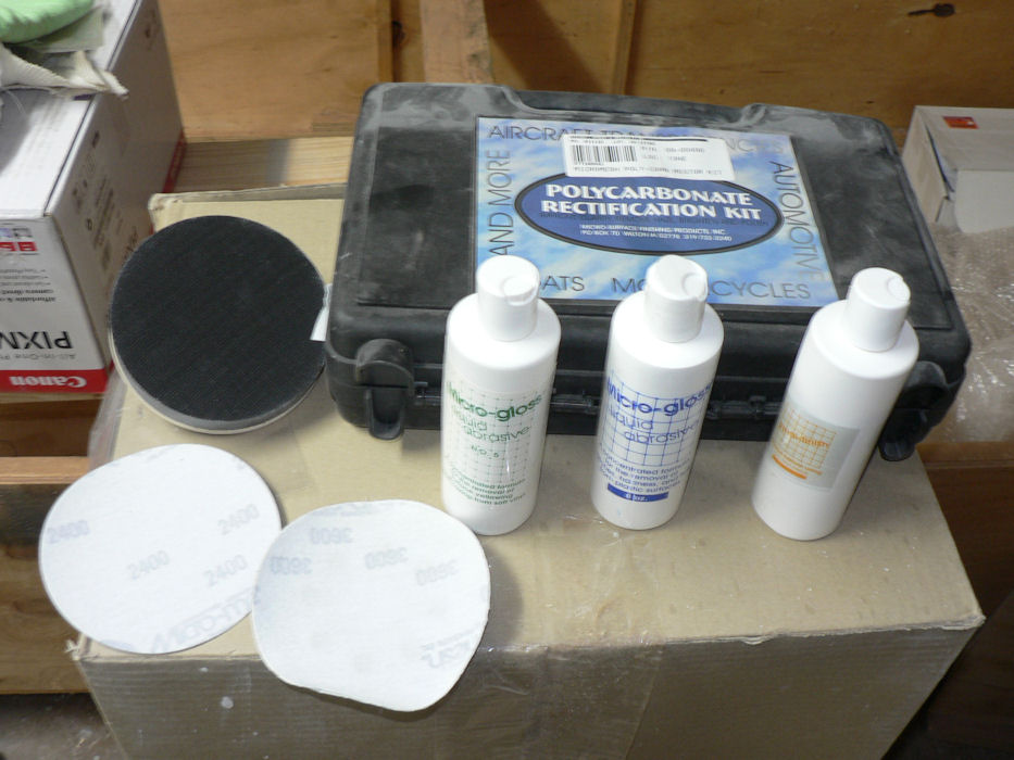
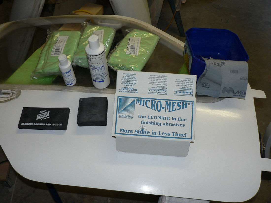
After temporarily fitting the port door and seeing that the window that I previously "polished" looked disgusting with lots of shallow scratches and even some paint spots, I had another go at it with the "polycarbonate Rectification Kit". That was a step up from what I had been using so far.
The first photo below shows most of what is in the kit. It included two sticky 5" sanding disks at 2400 and 3600 grit, and three different bottles of liquid polishing liquid together with a sticky 5" disk lambs wool applicator, and a sticky 5" sticky disk sponge applicator, a number of micro fibre cloths and a couple of flannel cloths. It also has a sticky disk holder with a spindle to allow it to be used in a normal drill chuck.
I supplemented that with my battery powered drills and a 240 volt orbital sander with a 5" sticky holder. A water spray bottle from the local supermarket was a very useful addition during the polish process.
[ATTACH]8896.vB[/ATTACH]
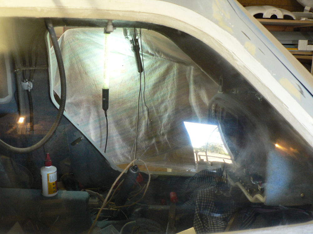
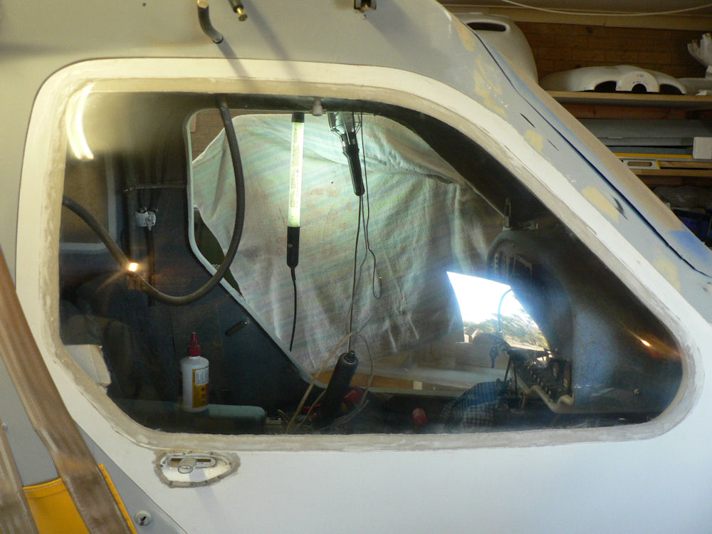
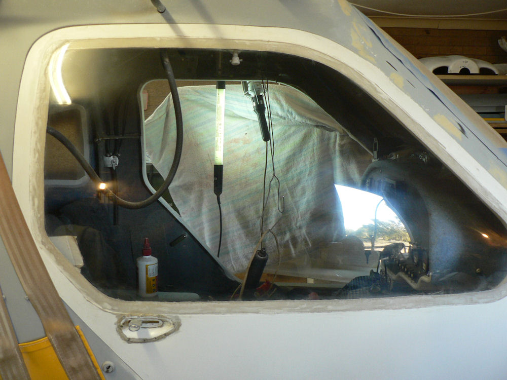
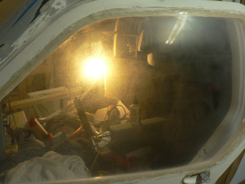
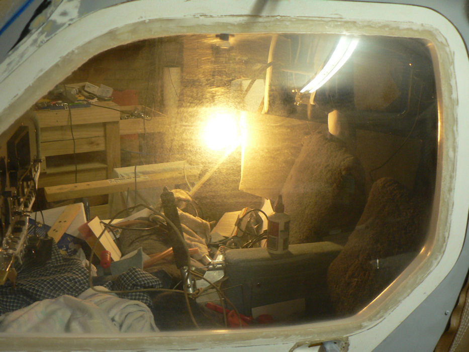
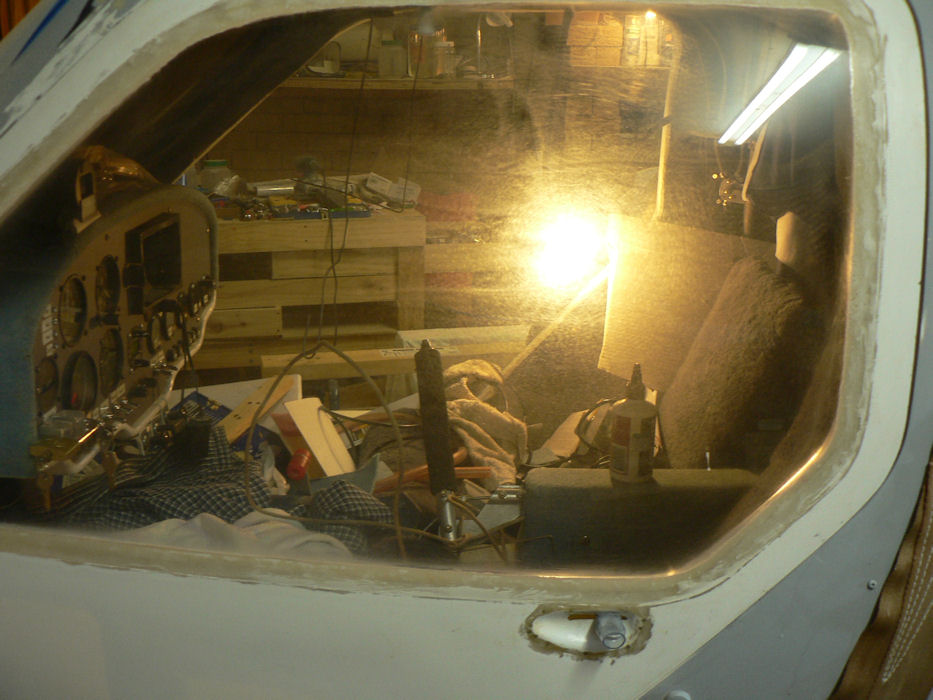
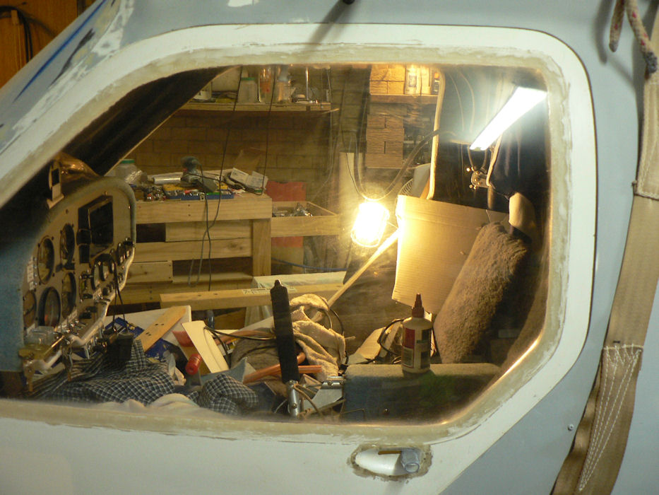
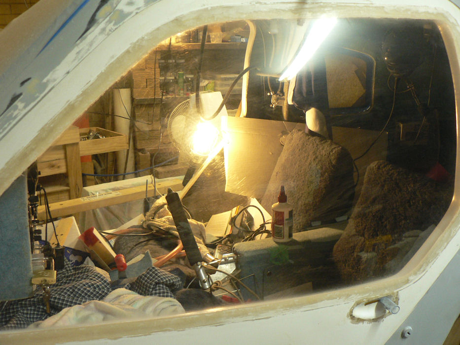
The photos below show the changing clarity of the polycarbonate after successive passes with the polishing process. The back light in the middle or left of the photos is an extension trouble light in the cabin. The bright spot on the upper right of the photos is a reflection of the neon lights in the ceiling above the A/C cabin.
[ATTACH]8897.vB[/ATTACH][ATTACH]8898.vB[/ATTACH][ATTACH]8899.vB[/ATTACH][ATTACH]8900.vB[/ATTACH][ATTACH]8901.vB[/ATTACH][ATTACH]8902.vB[/ATTACH][ATTACH]8903.vB[/ATTACH][ATTACH]8904.vB[/ATTACH]
Each pass started with a spray with water on the polycarbonate, then the first pass was a couple of goes with the 3600 grit using the drill to hold it with each run at right angles to the previous run. Once the grit was finished the window was washed and cleaned and then sprayed with water ready for the first liquid polishes which was applied with the lambs wool applicator again at right angles for each run. That liquid polish was repeated with a wash in
between polishes.
The next liquid was used for another couple of polishes with the same procedure of spraying and washing in between.
The last liquid polish was applied with the sticky sponge on the end of the electric drill.
The gear was all washed in a light detergent and hung up inside the house to avoid dust on the micro fibre cloths.
Both the inside and outside of the window was done. I spent about four hours on that window. It is not perfect but a big improvement.
-
Commenting on the post from Alan of FNQ.
He comments on the angle of the added deflector tab under the rear of the engine.
I would assume that it acts like an aerofoil section and would stall if it were attached with too great an angle to the bottom of the engine compartment.
So it would probably cause turbulence there and even result in higher pressures immediately downstream of it thus reducing the airflow through the engine compartment..
So Alan's more effective added tab that is at a flatter angle than the others makes sense to me
It would be interesting to know what those angles were!
-
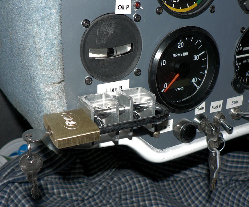
20091017 Fit security to ignition switches.
But first had my aviation fix at Narrandera with a couple of touch and goes and then a short flight to Leeton, Brobenah then return to Narrandera. It took a while to get organised as I did not know the arrangements for the aircraft, a Jabiru 230c, with the new owners now in possession. They had bought out Wally Rudin the previous CFI who was operating at Narrandera.
I am not sure at this stage how far I have to go with security.
So far this a/c has lockable doors, a lock on each door;
keyed main switch which operates a relay to turn off the battery power for the starter motor and all instruments in fact all connection to the battery except for the key switch.
Lockable bar for both ignition switches locking the battery independent ignition switches with a padlock. The engine can run with the main (keyed) switch turned off
Today's effort was to fit the lock to the ignition switches which had not been allowed for in the original panel layout.
Made up two aluminium channels with drilled holes to take the threaded portion of the ignition switches.
Drilled through side of channel to take long bar of a long padlock - relieved the far hole to allow for some curvature in the padlock.
[ATTACH]8882.vB[/ATTACH]
Had to remove an original panel screw situated between the switches and slot the ignition switch holes to allow the switches to be closer together to accommodate the length of the padlock.
Fitted another panel screw further around the panel below and to the right of the ignition switches. The screw is held by a retained nut riveted to the fibre-glass support.
-
I was under the impression that Jabiru alternators had been upgraded to a higher amperage output. Some pilots with new Jabiru motors might comment.
I think my older 2200 motor has an 8 amp alternator but I am yet to start it!
-
My J160 kit was number 14 and I presume they are scaled up versions of the LSA55 with some obvious changes.
One of the mandated jobs that had to be done by the kit builder for my kit as specified by Jabiru was to reinforce the wind screen pillars on each side of the windscreen and also down the backside of the door openings.
These reinforcements consisted of a thick strip of FRP alongside each windscreen pillars with extra glass layers on top and multiple layers of glass strips from the back of the door openings across to the next rearwards whale bone in either two places I think or maybe three. The effect on the windscreen pillars was to convert them into a more rigid closed triangle section with the windscreen lip along one corner of the trianglular section.
All these reinforcements would all probably contribute to the stability of the dimensions of the windscreen space under varying loads.
-
Are the pilots that are getting blockages in their carburetor jets using fuel with added ethanol?
It occurs to me that fiber glass fuel tanks with internal baffles, if they have them, would be particularly hard to slosh completely with tank sealant.
Any exposed glass would be subject to degradation from the fuel and it would probably end up in the small carburetor jets.
In my J160 kit #14 the original sealant was not suitable for use with fuel containing ethanol.
The hole saw cutout from one of the holes cut into one of the wing fuel tanks had an area about 40 mm diameter that was missing a layer of tank sealant making me very nervous about the integrity of the fuel tanks.
I do not know if the manufacturer had two lots of sealant applied - if so it may have been OK but there was still the area near the new holes in the tanks.
This was one of my incentives for sloshing my wing tanks which hopefully would allow the use of mogas if necessary and also seal around the additional fittings that are fitted by a kit builder, the tank filler hole and the drain hole.
There are plenty of old Jabs out there in Australia with wing tanks that are not suitable for use with ethanol added fuels.
-
20091007 Polish port door window.
The port side door window (the one below!) did not need nearly as much cleaning up as the starboard side door window so I only used the Micro-Gloss liquid without using the abrasive cloth.
Applied liquid to the window then spread and rubbed across the window generally working at about 45 degrees to each polishing pass.
Once the liquid had dried up while polishing continued to polish with a clean microfibre cloth until the window was clear.
[ATTACH]8849.vB[/ATTACH][ATTACH]8850.vB[/ATTACH]
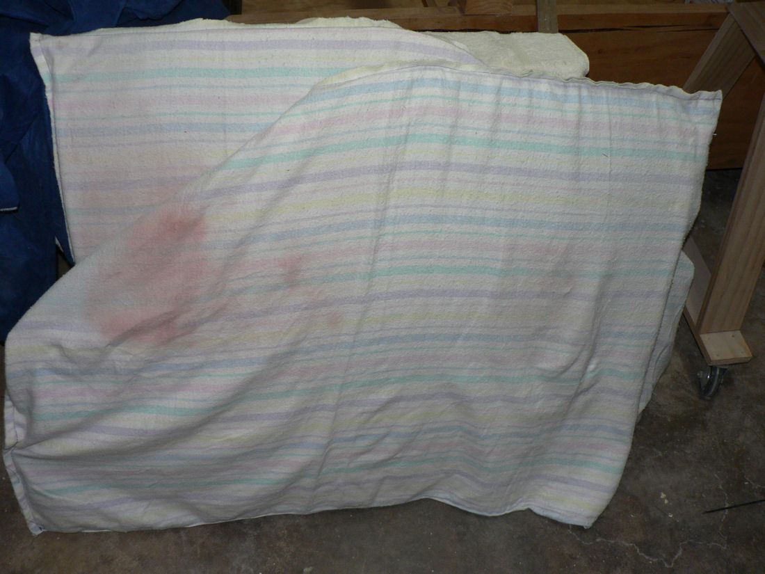
Talked my better half into making up two sets of covers for the doors out of old fleecy lined sheets which I had already been using for padding on top of saw horses. Should have done it ages ago.
Shall have to edit the previous post - it was the starboard door - two r's in starboard for right side.
-
20091005 Door Windows polish
A bit of hind sight advice here - "a wonderful thing".
All the scratches and mess on the door windows was basically my fault in not taking due care to prevent it.
Some suggestions.
The doors are a very awkward shape for holding and working on while inserting their windows. It probably would be well worth while to make up a frame to hold each door in a horizontal attitude for each way up securely while inserting and flocking in the windows.
Covering each door catch handle with a piece of plastic tube first might prevent any damage from that source on the windows.
The door frame holders could also help to store the doors with little risk of damage. Needless to say I had not done either of these suggestions - hence the need to buy kits to clean up the windows - probably al least $170 so far.
Located the scratches on the starboard door then used a series of wet & dry abrasive cloths ranging from 1,500 grit to 6,000 to gradually abrade the area around each lot of scratches. I kept the abrasive cloth wet during the following processes.
Making sure to work at least 45 degrees to any scratch mark that is being removed start with the coarsest cloth, 1500 grit, abrade the surface at an angle to the direction of the scratch until it disappears note that the cloth is making its own set of scratches but not as deep as the original scratches.
Use successively finer cloths to remove the previously coarser scratches until the last cloth is used. Wipe off the residue from each process.
Then applied Micro Gloss liquid abrasive onto a micro fibre cloth and apply it to the window. Rub it all over the previously cloth treated area. Keep rubbing in the Micro Gloss liquid until it disappears. If necessary apply more coats of Micro Gloss to get rid of any residual cloudiness from the abrasive cloth process.
The pictures show most of the contents of two repair kits.
[ATTACH]8843.vB[/ATTACH][ATTACH]8844.vB[/ATTACH]
The small bottle of Micro Gloss abrasive came with the abrasive cloths plus two small cotton linen cloths (not shown here) for applying the polish.
The other kit had the larger bottle of Micro Gloss abrasive liquid and four green microfibre cloths.
-
One of the forum members claimed something like that fibre glass tanks that are not completely lined with pure epoxy and possibly an appropriate tank sloshing agent will break down their fibre glass.
This makes it fairly difficult if the tanks have internal baffles which would probably be the case.
I am not sure if somebody said a similar message at the recent L1 meeting at Temora.
Regards
-
20090927 Sloshing the wing fuel tanks with Kreem
This job was actually done some weeks ago and I had taken photos during the operation but had apparently forgotten to write it up and also deleted the pics.
Bob Payne assisted me in this job as it's a bit difficult to upend wings on your own.
These wing tanks as supplied were originally sloshed with an agent unsuitable for use with fuel containing ethanol. So I decided to slosh them over the top of the existing sealant with Kreem as supplied and advised by by Jabiru at the time. I am led to believe that later model fuel tanks are now sealed to cope with fuel with added ethanol.
All the fuel line fittings from both wing tanks were removed and replaced with brass plugs from the local engineering supplies shop.
Sat each wing tank in turn on a pair of saw horses.
Mixed up a batch of Kreem diluted with acetone and poured it into the wing through the refuel hole and replaced the fuel cap.
Sloshed the Kreem/Acetone solution around the wing by rolling the wing back and forth and over a number of times and also turning it end over end a number of times.
After some time the outer end was raised, the drain plug was removed and the Kreem/Acetone mixture drained into a plastic jug.
This was repeated for the second wing.
Then it was repeated again for both wings using the remainder of the Kreem with a higher dilution rate of acetone.
I will probably do this again with a higher volume of Kreem solution.
I still have the header tank to do.
Hint for cleaning out jugs etc. Pour remainder of Kreem solution into airtight containers and then seal the lids to prevent it evaporating and going solid.
Do not attempt to wipe out the jugs with a rag - just let it cure.
Once it is cured get a knife under an edge and peel it off like a pair of gloves.
************************************************** *****
Today
Fairing for Rudder Cable exit.
Made up a fairing for rudder cable exit to rudder from aluminium sheet.
The first attempt was a failure with the cable not centered under the fairing. Old Drill holes will be filled, undercoated and sanded.
The first attempt is shown together with the final version fitted but it will be removed, smoothed cleaned up and painted ready for installation.
The fairing will be attached using SS screws fitted after fuselage painting to allow it to be fitted and removed without damaging the final coat on the fuselage.
*********************
I had an extra photo that I could not get rid of despite deleting it from the inserted pic list in the text. It still appeared at the bottom of the post.
I eventually highlighted all of the the post and copied it with a Control-C command except for the unwanted picture.
Then created a new post session and pasted the copied data into the new post and then saved it.
Then went and deleted the previous post with the extra picture that kept reappearing.
-
We need an instructor here to explain what happens in a tricycle undercarriage aircraft like the Jabiru with the nose wheel linked to the rudder pedals.
Think about it. Most landings have a small crosswind component so where has the rudder pedals got the front wheel pointing when you touch down on the mains only hopefully in any sort of a crosswind or nil x-wind. What doesn't help the learner is that you usually cannot see the rudder pedals or an indicator telling you where they are.
The aircraft is almost a land vehicle with the mains on the ground and now being steered by the rudder. Where is the front wheel pointing now in the X-wind with only the mains on the ground.
So where have the rudder pedals got to have the front wheel pointing when it eventually touches down.
No one ever spelled out to me exactly what happens at this vital point in landing a tricycle undercarriage a/c and it took me a long time to work it out as I did most of my early flying in gliders most of which were tail draggers.
-
20090730
Got back from Sydney on Friday 24th in time for the Christmas in July Fly In at Brobenah for the Luskatyn Tigers who had also flown in earlier in the year. Apparently we had saved up more than enough cold weather for them. By Saturday night I had lost my voice and all I could do was watch and listen. I did not make it back to the strip on Sunday so only got a few pics.
[ATTACH]8487.vB[/ATTACH][ATTACH]8488.vB[/ATTACH][ATTACH]8489.vB[/ATTACH]
The particular one here, a very special J160 with a 3300 looks a very nice a/c and I saw it take off quite a few times.
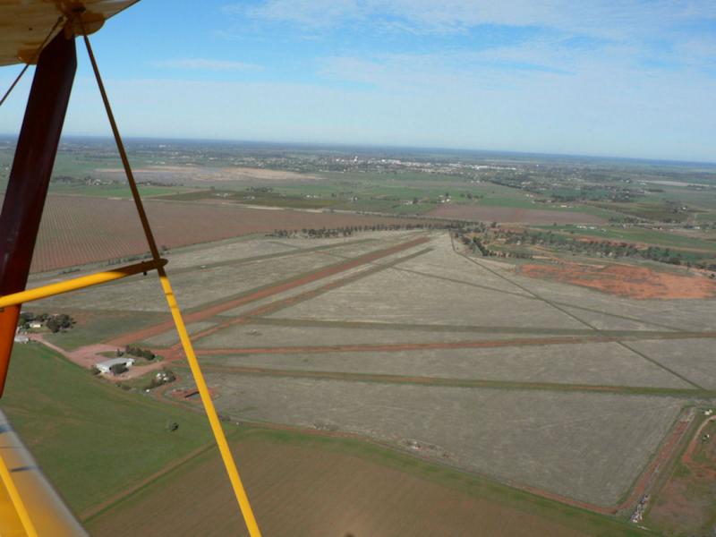
I was offered a ride in a Tiger which I gratefully accepted and managed to get a pic of Brobenah (Leeton) airstrip(s) in the pic with the town of Leeton about 5 km away in the background. The white blob in the middle of the town is one of the water towers that feature in the town. Now I know why I am building a kit plane with an enclosed cabin with a heater!
[ATTACH]8490.vB[/ATTACH]
For those that know the strip the Aviators Club House is just in the bottom left hand side of the pic with its attendant hanger just missing out. Just over the road the previously bare paddock is now covered with thousands of walnut trees (I think), about three or four metres high.
Part of the local car club track is in the bottom right hand corner and the big red area in the middle right side is the now covered up rubbish tip which is no longer in use. A new much greener one is located due east of the town.
Basically all the grey looking area is the airfield with part of it out of the picture on the left and on the right, about 600 acres altogether.
-
Thanks Decca but I still feel there are a great many people out there who have many more miles of knowledge and experience than I so I love this site where sometimes we can extract a bit more of that information and experience and get it spread around a bit more without having to learn it the hard way.
The J160 build has stalled a bit lately due to a few personal negatives that all ganged up on me at once but there have been some pluses which will ease the problems.
The J160 is really not that far from completion in terms of numbers of jobs to do on it, but some of them may take some time. Every time I add a bit more fill & rub it back it seems that it needs some more filling - at least on my last trip to Wagga I found where my paint supplier had moved to and managed to get a very smart mixing stick from them which allows you to make up a batch of paint or filler in any one of a number of finished depths of the final paint mix.
All you need to go with it is a container with vertical sides so that the intervals on the paint ruler relate to the correct volume ratios. I also got a new tin of filler in a non leaky container making it easier to handle and so I can also slop it around a bit more extravagantly which might make the process a bit faster.
I was verbally assured that the painted on ratio marks are supposedly proof against the paints and thinners for which the mixing stick is designed.
The mixing measure stick is a pretty obvious idea once you have seen it. I was tempted to photograph it and post it here but I would probably be breaking copyright if I did so. The ruler is supposed to be proof against the solvents for the paint mixes nominated on its scales.
But I think that I might make up a metal or wooden model that has steps on it for each component of the mix - so you don't have to read a line covered in paint -
just fill it to the top of each step for each component - then fill it to the next step for the next component etc. The trouble with this approach is that you need a different stepped stick for each total volume size that you might want to use. I am initially thinking of using a strip of thin aluminium which is nicked with three Vs at each set of depths required.
Part of their mixing stick for example that copes with Universal 2K Primer has marks for the Universal 2K Primer, the Activator and the surfacer thinner in ratios of 4:1:2 and for these ratios actually has seven (7) sets of those which range from a minimum mixed depth of 35 mm up to a maximum mixed depth of 245 mm.
It also has another scale with a ratio of 4:1:3 in seven depths up to a maximum depth of 280 mm.
The last component of those ratios is the thinner which you obviously can increase or decrease without altering the ratios of your base paint and its activator depending on the needs of your spray gun and the job.
The only drawback is that I had to organize a few vertical sided containers so that the scales give correct volume ratios. But vertical sided Milo tins with the tops cut out or left on if you have enough of them would do the trick.
These two part paints once they are mixed up go off in maybe less than twenty minutes depending on the temperature of the paint. The time to go off can be extended by cooling the paint, slowing down the chemical reaction!
I had my flying fix last Saturday with a few check circuits with Wally Rudin in the J230 at Narrandera then another hour by myself of local flying Narrandera Leeton Brobenah and a couple more touch and goes to finish off. Despite there being plenty of small cumulus clouds it was a beautiful day for flying.
-
Take all of the following with a grain of salt.
I was not a gliding instructor, and had relatively low experience in gliders. I am not flying gliders now.
My memory flying gliders is getting a bit vague but for the Club Libelle I was pleasantly impressed by its trailing edge dive brakes compared to "convential" types which extended generally above and below the wing as described by others below.
In the Club Libelle, a fibreglass single seater with a best glide of about 1/35 if my memory is correct, the dive brakes as one surface extended below and above the wing trailing edge thereby having some flap effect with its attendant drag and a very significant speed limiting effect when fully extended. The extension of the surface above and below the wing balances some of the forces on the flap handle making it easier to fine tune its application as you come in to land.
The change in stall speed with fully extended dive brakes was about two knots whether it was raised or lowered I can't remember.
The Club Libelle was an entry level single seat fibre glass sail plane with medium performance for its day, not equiped with flaperons, therefore no negative flap equipment and did not carry water ballast.
The very effective dive brakes reduced the risk of being sucked into a cloud by a very strong thermal as one could pull full dive brakes and put it into a very steep dive and the airspeed would be limited to about a constant 80 knots.
I have experienced a plus 20 knot indicated on the VSI in a glider you can imagine what airspeed you might have to get up to to wash that off without using dive brakes.
One school of thought was that the quickest way down was to spin the aircraft and I once worked out that a spinning L-13 Blanik, a twin seater aluminium glider with a glide ratio of 1/32 at best glide speed would have a VSI of 80 knots vertically down if held in a spin. Blaniks were known to be able to get into flat spins if incorrectly loaded.
For the Club Libelle:
I think its VNE was about 108 knots.
Was the max rough about 90 knots or lower?
Its best glide speed was about 45 knots which was pretty close to the stall when you were in rough air with a fluctuating air speed.
It scared the hell out of me one day when thermalling (circling in rising air) fairly low to find myself without warning with the windscreen full of a very good picture of the surface below the aeroplane. But it recovered fairly quickly that time and I am still around.
PS: Decca please explain reflex flaps for mugs like me.
I liked the Blanik flaps (whatever they were called) that ran out when extended helping to lower the stall speed but they were prone to a lot of wear and tear.
-
I felt fairly safe pulling over a 2200 Jab motor by hand because it needs +300 RPM to fire the fuel in the cylinder according to the Jabiru engine manual.
However an instructor was not impressed and said that it could fire from a piece of still glowing carbon on the head or the top of a piston which is a possible scenario for a flying school operation with multiple flights with short delays between each flight.
I suppose that is fairly unlikely if it has been in a cold hanger all night and this is the first engine start.
The 300 rpm magic speed may be affected up or down by the clearance between the permanent magnets on the flywheel and the coils mounted on the engine frame.
Personally on a Jabiru motor I would rather spin the engine with closed throttle and no choke with the starter motor to get oil pressure with the ignition switches off.
Then for a cold motor situation, mags on, choke on, throttle closed, activate starter as soon as the motor fires close the choke.
If the idle is set high on a Jab motor the choke will be ineffective.
Of course as one of the others indicated if either of the grounding wires to either coil breaks a connection then that is the same as that ignition switch being turned on with the additional problem that the only way to stop the motor then is to turn off the fuel with the master tap and wait until the carburetor runs out of fuel.
I saw that happen once with a powered Aerochute where the wiring system for the earthing switch can be damaged or compromised by a heavy landing.
-
The Jab service bulletin shifting of the cable should help.
An additional point not mentioned in the SB was that at the level one course at Temora this year one of the instructor guys said that he has rejuvinated a number of "stuffed" Jabiru starter motors by simply removing the O rings in the outer casing of the starter motor.
Apparently the O rings were causing a reduction in the available volts and amps available to power the starter.
The other little gem that my Kit Fox flying brother has used on hapless Jabs with good effect was to boil up a Jug of hot water and pour it over the cylinders.
Other people have used hair dryers.
Batteries also have a bit more life when not stone cold but would take a fair bit of time to warm them a few degrees because of their large mass.
People in North America have been known to have an electric blanket on the floor of their garage under the engine bay of their cars to give them a non freezing start in winter.


External power connector
in Jabiru
Posted
Leads
I can imagine an aircraft with a busted U/C leg sitting in a pool of Avgas with two live connections to the battery under the cabin floor or very near it.
