

Ross
-
Posts
729 -
Joined
-
Last visited
Content Type
Profiles
Forums
Gallery
Downloads
Blogs
Events
Store
Aircraft
Resources
Tutorials
Articles
Classifieds
Movies
Books
Community Map
Quizzes
Posts posted by Ross
-
-
get more earth
For detail see the service letter on the Jabiru website
It might also pay to check the gap between the permanent magnets on the flywheel and the coil which according to my construction book should range from 0.010" to 0.012" or 0.25 mm to 0.30 mm.
-
17-09-2008
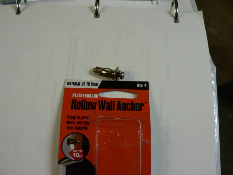
A little job today - the previously installed headphone hanger on the roof of the cabin in the luggage area was attached with two self tappers and these were were pulling out.
So replaced them with a couple of "Hollw Wall Anchors"
[ATTACH]6529.vB[/ATTACH][ATTACH]6530.vB[/ATTACH]

-
15-09-2008
Jabiru Engine Flywheel Attachment JSB 012-1
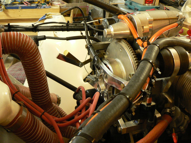
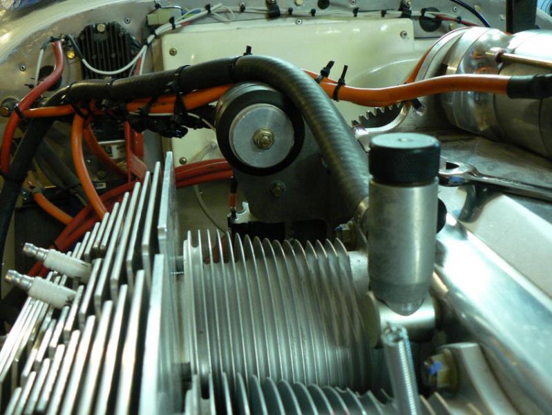
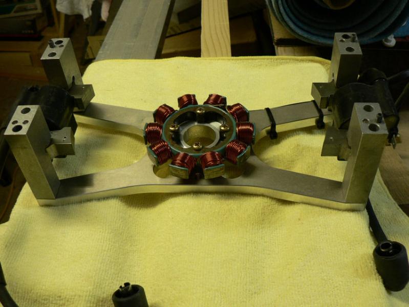
Replaced the alternator stator back in place with the mounting plate stand-off roll pins lined up with the matching holes in the engine backing plate.
Then gently tapped the alternator mounting plate with a light soft hammer on each corner until it was seated on the engine backing plate with the alternator stator back inside it's ring and each roll pin in both of their matching holes.
Reinstalled the alternator mounting bolts with Loctite 620 on the threads after cleaning them with Loctite 7471 and tensioned them to the backing plate through the standoff brackets.
Reinstalled the port top engine mounting fittings and bolt after doing the stand-off bolts.
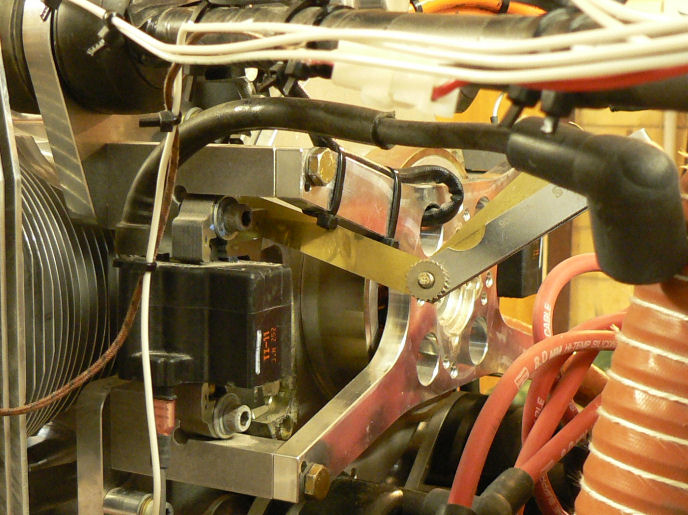
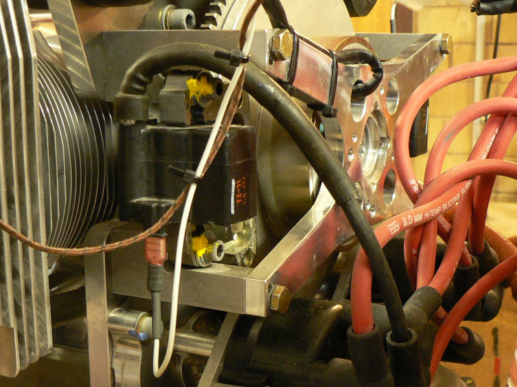
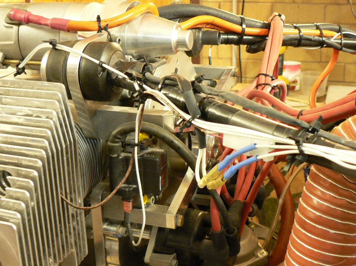
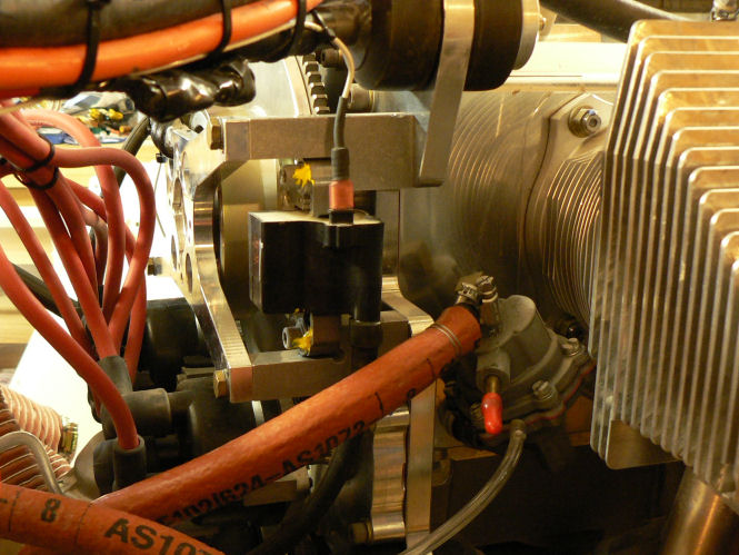
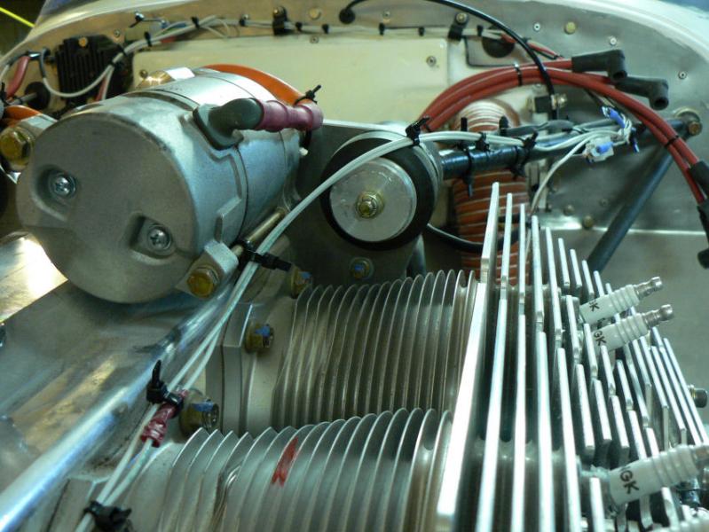
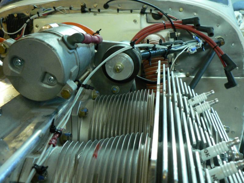
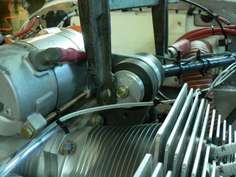
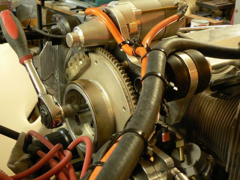
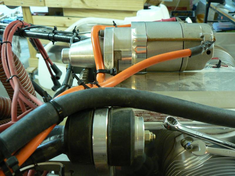
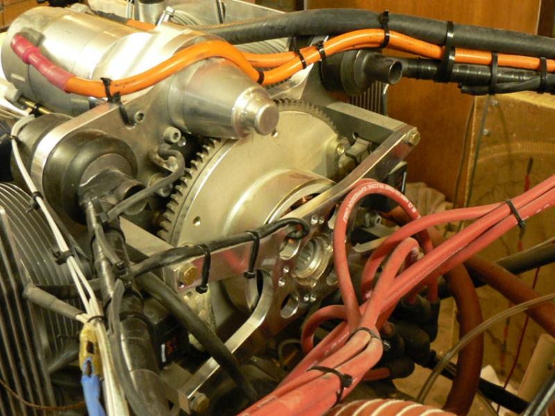
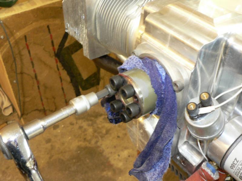
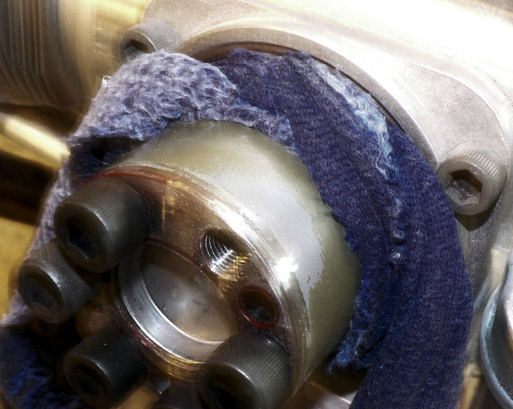
It was found that the port side ignition coil was just fouling one of the permanent magnets on the flywheel. It could be rotated but was just touching the magnet as they passed.
So in turn each pair of ignition coil mounting cap screws were loosened off to allow the coils to magnet gaps to be adjusted and set.
Because of the heavy magnetic pull of the magnets on the iron cores of the coils the non magnetic soft feeler gauge needs to be inserted in the required gap space before the coil is allowed to move towards the magnet.
A soft feeler gauge also allows the gauge to conform more closely to the curved space between the magnet and the ignition coil body.
As I only have one such gauge (two would be preferable) the end of the coil without a feeler gauge blade was only slackened enough so that it could rotate when the other end was adjusted.
So it took a couple of tries to get both ends of each coil gap to magnet within the allowable range from 0.010" to 0.012" or metric 0.25 mm to 0.30 mm gap.
[ATTACH]6512.vB[/ATTACH][ATTACH]6513.vB[/ATTACH][ATTACH]6514.vB[/ATTACH][ATTACH]6515.vB[/ATTACH][ATTACH]6516.vB[/ATTACH][ATTACH]6517.vB[/ATTACH][ATTACH]6518.vB[/ATTACH]
Once the gaps were set the cap screws were tightened up, checked again then marked with "Torque Seal" to make any looseness obvious on visual inspection.
All the disconnected leads were reconnected to the distributors, wiring harness and the removed cable Zip ties replaced to secure the wiring.
To make it easier to rotate the engine and check the gaps and make sure there was no fouling of the magnets or coils a spark plug was removed from each cylinder which was replaced at the end of the adjustments.
-
14-09-2008
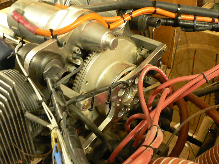
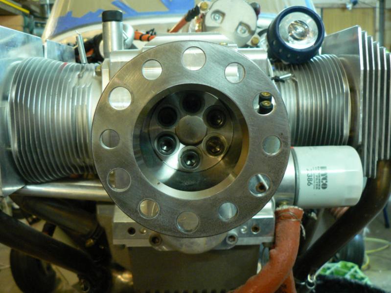
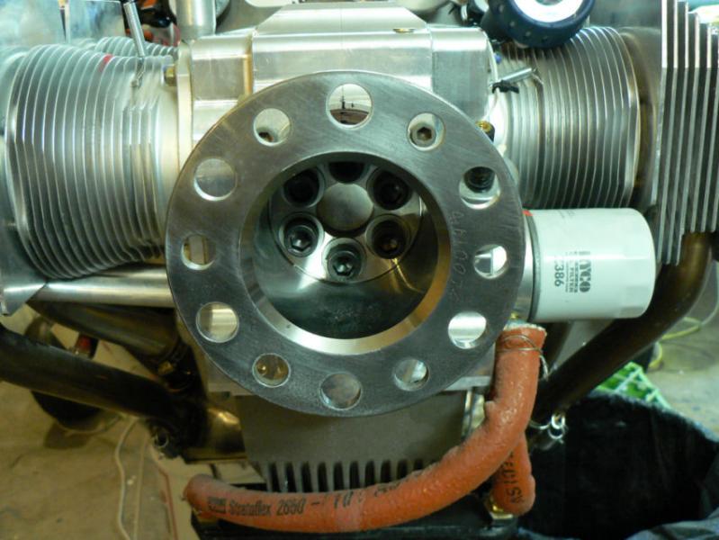
Jabiru Engine Flywheel Attachment JSB 012-1
The engine I have is a 4 cylinder Jabiru 2200A model, serial #1906 with zero hours TTIS.
According to the service bullletin this motor should have and has mechanical tappets and should have and has upgraded Cap Screws from 1/4" UNF to 5/16" UNF holding the flywheel to the crankshaft with no dowels (which became standard from the factory a few editions later on together with hydraulic tappets).
According to Jabiru, this motor may remain in service until a major overhaul is due at 2,000 hrs TTIS at which time the motor is to be modified to to include dowels for securung the flywheel on the proviso that it is inspected now to make sure it has no brocken or loose cap screws, has 5/16" UNF cap screws in the flywheel, the tension is raised to 24 lb feet and a different application of Loctite is done on each cap screw.
I have also discovered today that later models now have a steel flywheel instead of the current one which looks like aluminium.
Disconnect the alternator wiring from the loom going to the firewall & rectifier.
Disconnect the ignition circuits from both coils as well as the HT leads to both distributors.
Snip off a number of cable ties to facilitate cable movement.
Disconnect the port upper engine mount to gain access to one of the alternator mounting bolts.
Removed the alternator by undoing the 4 attachment bolts that hold the star shaped alternator mounting plate & the stand offs which were bolted and located by roll pins into the engine backing plate behind the flywheel near each of the four bolts holding the mounting frame.
Replace the port side top engine mount so the engine mount does not get distorted.
The alternator has to be gently prized from its location using a piece of wood carefully so as not to distort or damage the altenator mounting frame.
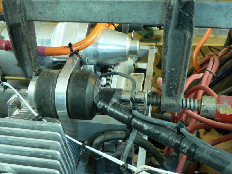
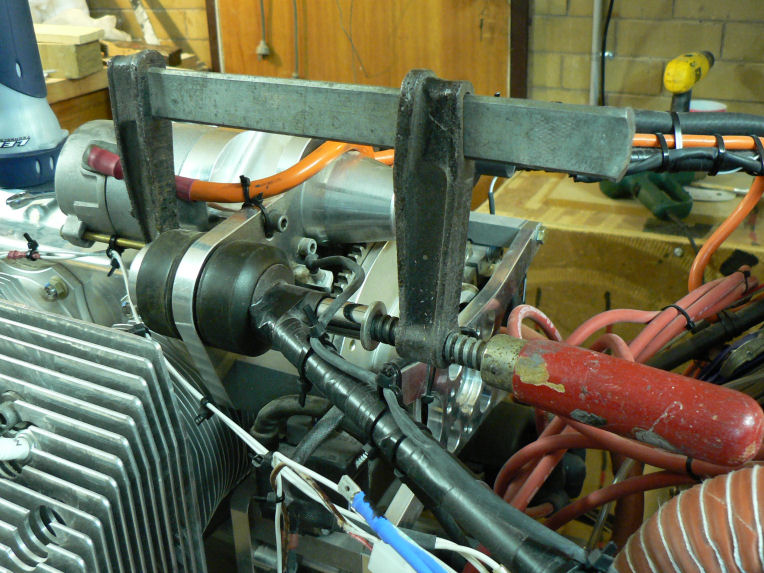
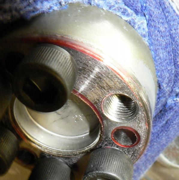
Once the alternator has been extracted against the pull of the magnets and the friction of the locating roll pins, the six Cap Screws with Bellville washers holding the flywheel to the end of the crankshaft are exposed to view and prove to be correct as being 5/16" UNF for this particular engine serial number.
The tension needs to be checked at 24 lb. feet for 5/16" UNF cap screws but cannot be checked reliably because they are Loctited in place.
So for each cap screw, one at a time, the following proceedure was done:-
Each cap screw was heated for one minute with the hot air gun which was sufficient to be able to extract the capscrew without damage occuring.
Each cap screw was sprayed with Loctite 7471 as well as the corresponding tapped hole in the end of the crankshaft.
The thread of each cap screw was steel brushed to remove old loctite and then sprayed again.
The cap screw was run back into the tapped hole then removed and the hole blown out with compressed air and the cap screw cleaned again.
The cap screw then had Loctite 620 added to the tip of the screw and up near the shank.
The cap screw was reinserted & tensioned to 24 lb. feet.
Once each of the cap screws had been inserted, tensioned and marked with black textra they were all heated and checked for tension again at 24 lb. feet.
[ATTACH]6498.vB[/ATTACH][ATTACH]6499.vB[/ATTACH][ATTACH]6500.vB[/ATTACH][ATTACH]6501.vB[/ATTACH][ATTACH]6502.vB[/ATTACH]
[ATTACH]6503.vB[/ATTACH][ATTACH]6504.vB[/ATTACH][ATTACH]6505.vB[/ATTACH][ATTACH]6506.vB[/ATTACH]
The original cap screws were all under tension with no brocken ones otherwise they would have all needed to be removed with the flywheel before inspection and replacing all the cap screws and possibly the flywheel as specified in the service bulletin.
Continued to-morrow after a few jobs.
-
13-09-2008
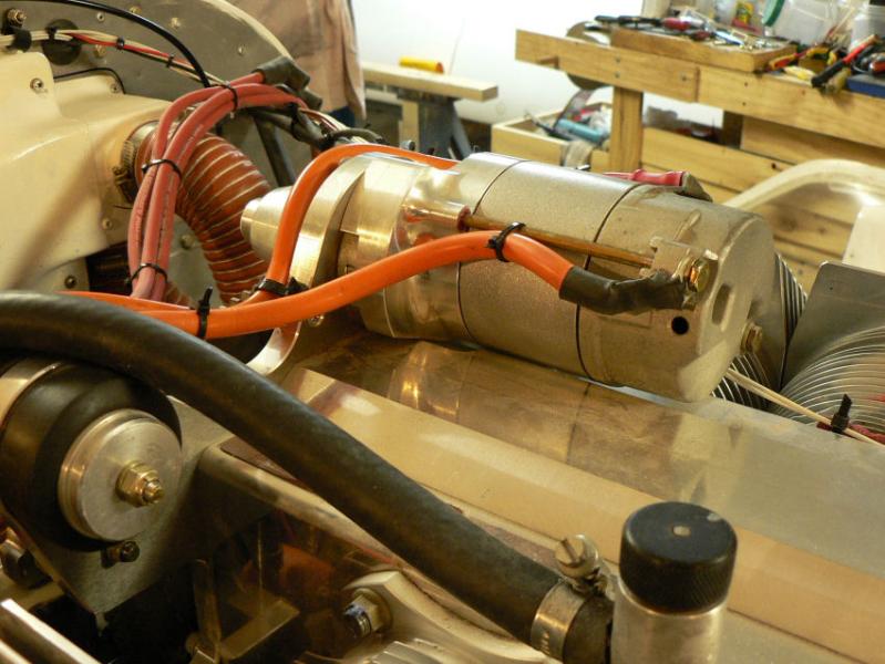
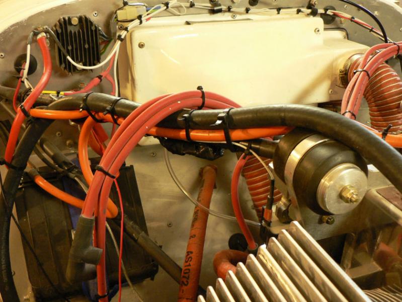
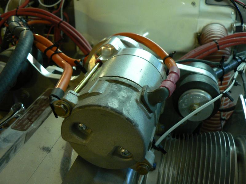
Starter Motor Earth Cable JSL 005-1
The earth cable for the starter motor was removed from the ring gear end of the starter motor to the propeller end of the starter motor by using the starter motor through bolt as the earth connection to the cable.
The cap screw from through the engine backing plate was cleaned up and replaced back into the motor through the backing plate into the motor with a suitable washer and a small amount of Loctite 243.
The contact against the back of the starter motor was cleaned to make a good earth contact.
After being removed to attach the earth lead, a long through bolt was reinserted through the earth cable with a suitable washer and Loctite on the thread.
The cables were tied down again with zip ties.
[ATTACH]6494.vB[/ATTACH][ATTACH]6495.vB[/ATTACH][ATTACH]6496.vB[/ATTACH][ATTACH]6497.vB[/ATTACH]
The new arrangement should result in less electrical resistance in the stater motor wiring circuitry.
-
13-09-208
Prop Flange Cap screws JSB 022-1
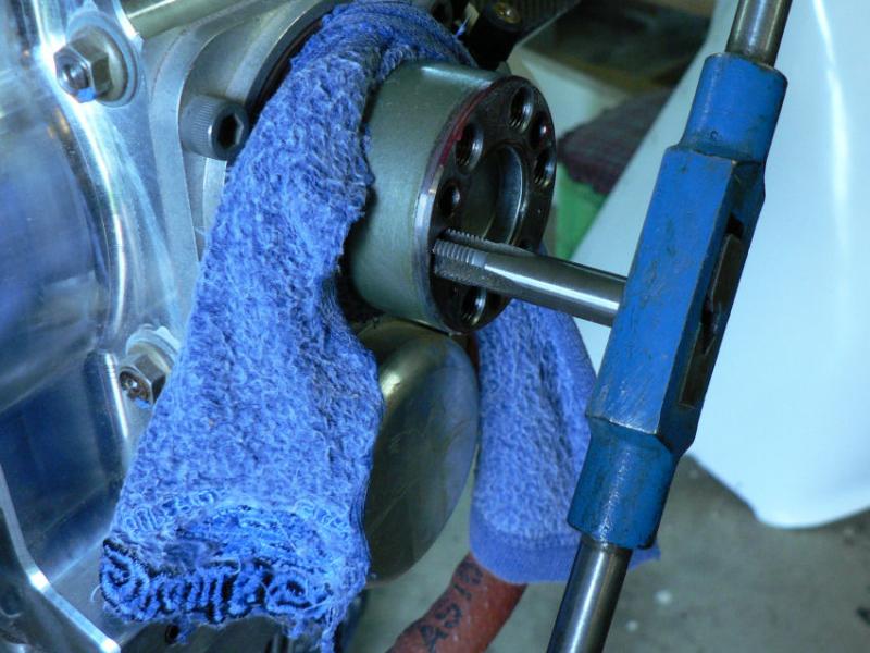
The tapped holes in the crankshaft were sprayed out with Loctite 7471 then cleaned out again with the 3/8" UNF hand bottom tap to the bottom of the threads.
The threads were then washed out again with Loctite 7471.
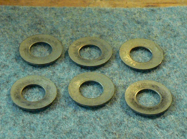
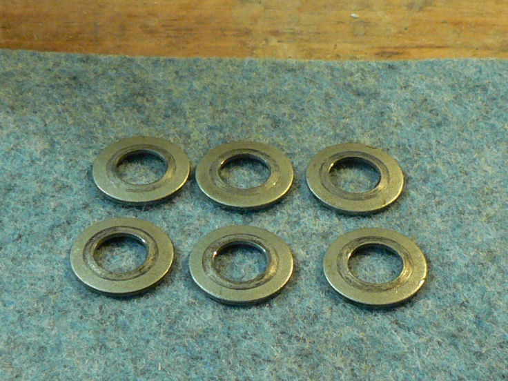
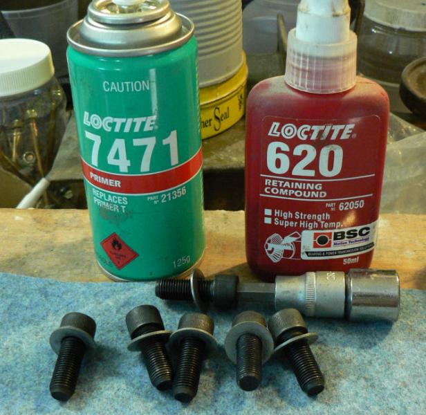
The six new 3/8" UNF x 1" long cap screws were cleaned with Loctite 7471 as were the faces of the crankshaft, the propeller flange and both sides of the Bellville washers.
After the cap screws and the holes had dried out the screws were assembled with the Bellville washers and some Loctite 620 (about a large match head size) applied inside the tapped holes and on the top of the thread of the cap screws.
The six cap screws and Bellville washers were inserted by hand using the socket set through the propeller flange into the crankshaft.
[ATTACH]6490.vB[/ATTACH][ATTACH]6486.vB[/ATTACH][ATTACH]6487.vB[/ATTACH][ATTACH]6489.vB[/ATTACH][ATTACH]6488.vB[/ATTACH][ATTACH]6491.vB[/ATTACH][ATTACH]6492.vB[/ATTACH][ATTACH]6493.vB[/ATTACH]
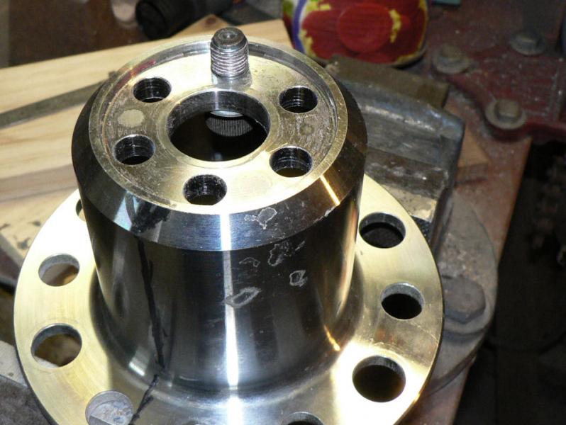
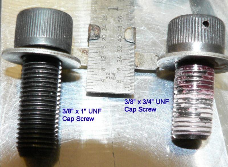
Pic 1 shows the difference between the old and new set screws both with Bellville washers under the head with a piece of wood inside the flange to hold the screws up.
They were then tensioned immediately in stages through 20 lb.feet, 25 lb.feet and 30 lb.feet working in a diagnal pattern around the flange to prevent distortion of the flange. As my tension wrench is calibrated in Newton Metres I had to do the calculation for the conversion before starting the cap screw tensioning.
-
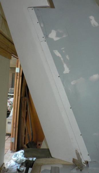
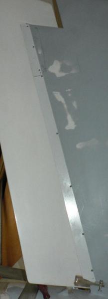
11-09-2008
Moved down to the other end of the A/C as the prop flange connection has been making me feel nervous.
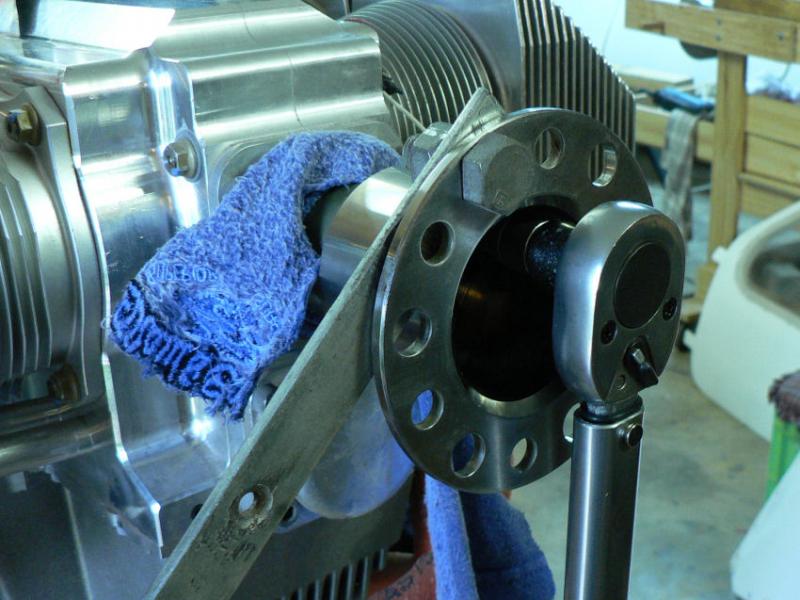
Removed the spinner and the propeller.
Wrapped a cotton rag around the crankshaft just in front of the front crankshaft oil seal and soaked this rag with water to keep the heat from damaging the oil seal.
Applied some heat to the outside of the prop flange.
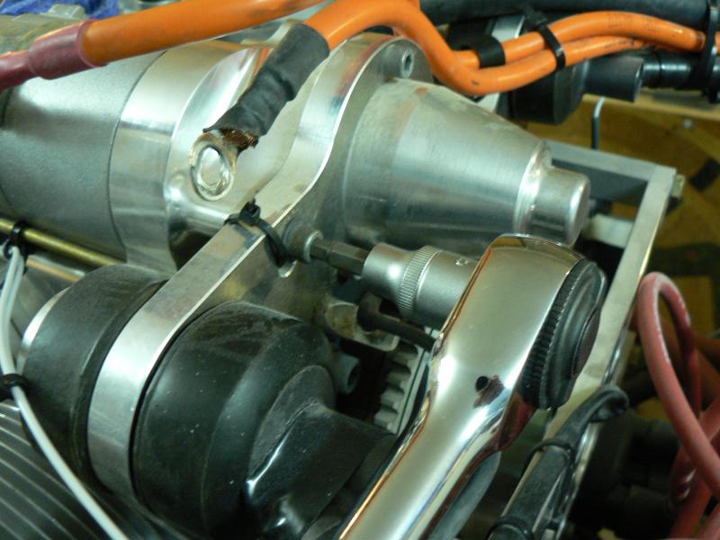
Then heated the cap screws from inside the front of the prop flange with the hot air gun until the cap screws could be loosened with a ratchet spanner plugged into the top of the cap screws.
Tried small increases in heat until the screws would come out to avoid using too much heat which might damage the front crankshaft oil seal.
Removed the prop flange which had 3/8" UNF x 3/4" long caps screws Loctited into the tapped crankshaft.
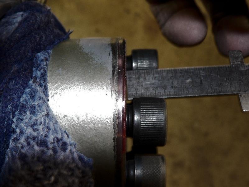
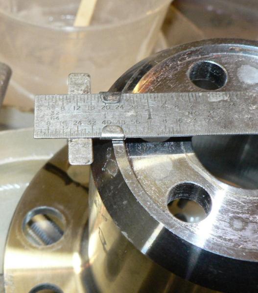
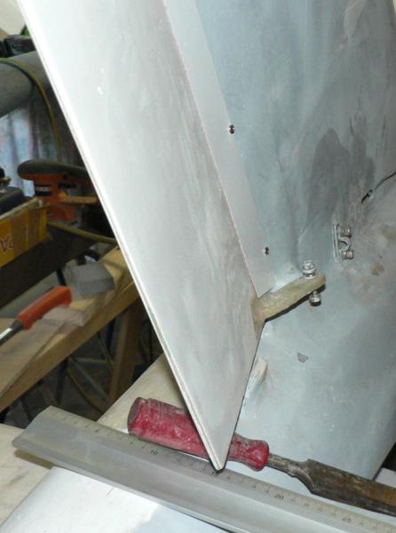
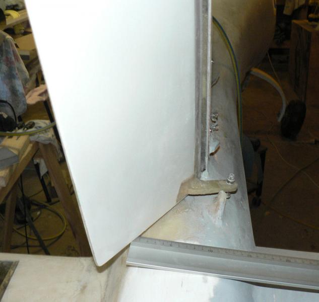
Measured the thickness of the prop flange where the cap screws go through it, the length of the screws, the thickness of the Bellville washer used on the screw, the amount of lost thread in the top of the tapped hole in the crankshaft and the lost thread on the end of the cap screws.
When you allow for loss of effective thread at the start of the tapped hole and on the end of the 3/4" long cap screw it is apparent that the amount of full engaged thread when using 3/4" long cap screws is marginally less than that set in the Service Bulletin JSB 022-1 dated 28th July 2008 for the "Propeller Flange Attachment". It quotes 9 mm or 0.354" of full thread engagement.
The flange including Bellville washer is about 8.3 mm thick.
Take that from a 18.7 mm long cap screw leaves 10.3 mm which looses about another 2 or 3 mm of effective thread putting it under the 9 mm set in the service bulletin
Ran a 3/8" UNF Bottom tap into all six tapped holes in the end of the crankshaft to clean out the Loctite 620 and then blew them out with an air hose.
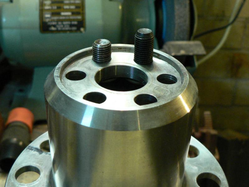
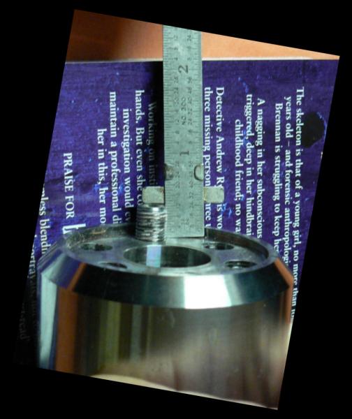
The holes are one inch deep and a 3/8" x 1" long UNF cap screw can be screwed in until the thread stops it leaving about 3/32" clearance between the head and the crankshaft face.
The flange plus the Belville washer is about 8.3 mm or just over 5/16" thick so that if 1" long cap screws are used with a Bellville washer instead of 3/4" cap screws there should be about 7/32" clearance under the cap screws before they bottom in the threads in the tapped holes in the crankshaft.
Grinding off the slight taper on the end of the cap screw would probably not increase the clearance as that part of the cap screw can probably go slightly deeper than the end of the fully tapped thread because it is a smaller diameter than the root of the thread.
See the longer cap screws being tried out and measured for clearance in pics 2, 3, 4 and 5.
[ATTACH]6471.vB[/ATTACH][ATTACH]6472.vB[/ATTACH][ATTACH]6473.vB[/ATTACH][ATTACH]6474.vB[/ATTACH][ATTACH]6475.vB[/ATTACH][ATTACH]6476.vB[/ATTACH][ATTACH]6477.vB[/ATTACH][ATTACH]6478.vB[/ATTACH]
So using 3/8" x 1" long UNF Cap screws should give a more secure attachment of the prop flange.
I will still apply Loctite 620 as per the Service Bulletin after cleaning out the Loctite 620 with Loctite 7471 activator (primer) on both the cap screws and the tapped holes in the crankshaft.
-
09-09-2008
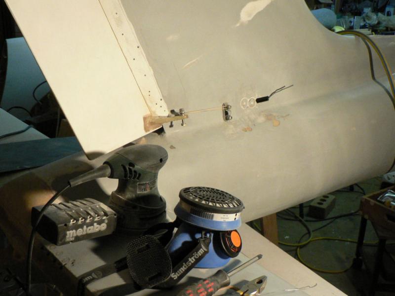
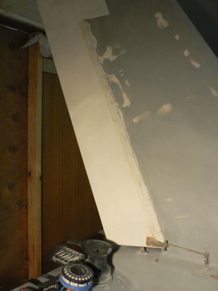
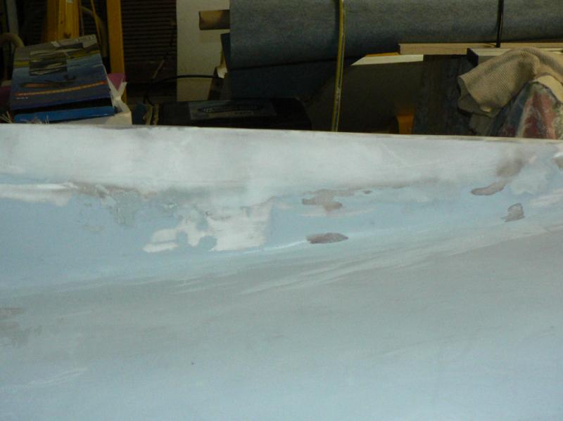
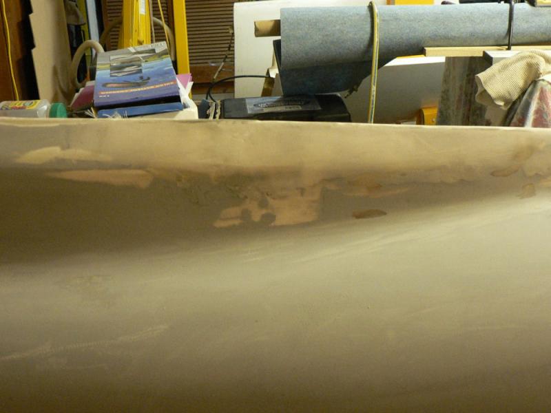
Scraped the the high spots off the micro-ball epoxy fill used on the rudder gap cover both on the starboard outside of the vertical stabiliser and on the inside of the channel at the aft end of the vertical stabiliser.
Then used the orbital sander on the cover strip and join area of the vertical stabiliser.
[ATTACH]6449.vB[/ATTACH][ATTACH]6450.vB[/ATTACH][ATTACH]6451.vB[/ATTACH]
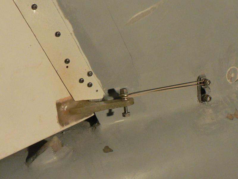
The light rubber band will still hold the rudder against the stop. Because the rudder hinges are on the port side of the rudder and the mass balance weight on the top of the rudder, the rudder tends to sit at almost full left rudder when not connected to the rudder cable.
Epoxy Micro-ball fill is difficult to use on a vertical surface as it remains plastic for so long before curing in the cool temps we are experiencing in late afternoons and nights. If it is used very stiff there may not be enough epoxy available in the mix to give good bonding with the underlying surface.
So I will need to use the two part bogging undercoat to make a good base for the top coat in this area.
-
08-09-2008
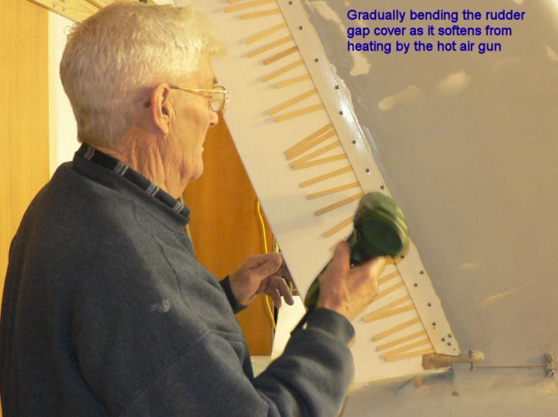
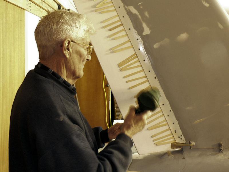
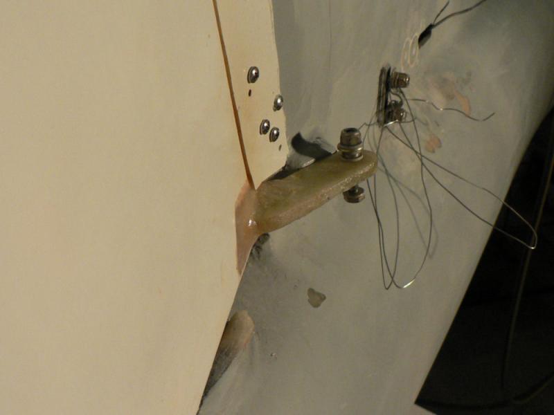
Fitted rudder to check rudder clearance against new gap cover strip.
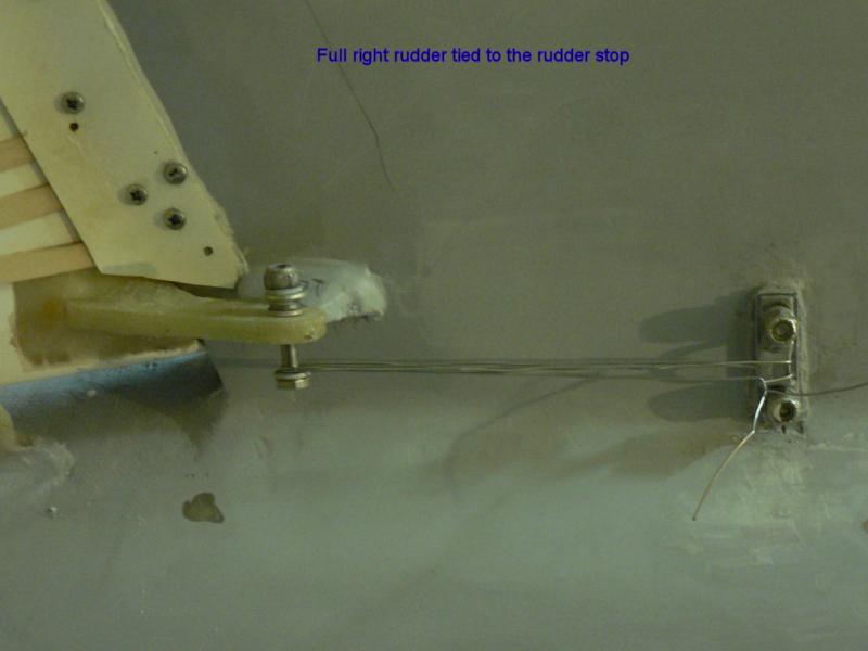
Applied hot air from hot air gun to cover strip as it was moved over against the rudder stop at "full right rudder" position.
Once that was achieved with rudder touching the cover strip - tied the rudder with lock wire against the stop.
[ATTACH]6432.vB[/ATTACH][ATTACH]6433.vB[/ATTACH][ATTACH]6434.vB[/ATTACH]
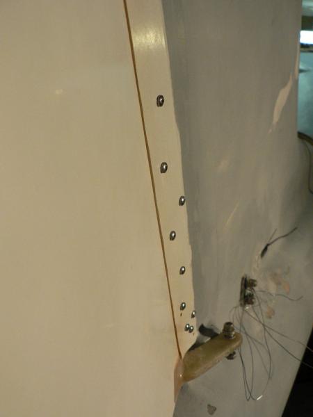
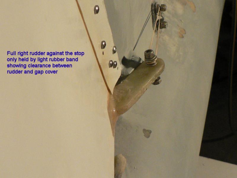
Applied more heat to the cover strip and inserted mixing sticks (paddle pop sticks) as spacers between the cover strip and the full right rudder position.
Allow the cover to cool and set in position with mixing sticks maintaining clearance.
Removed mixing stick spacers.
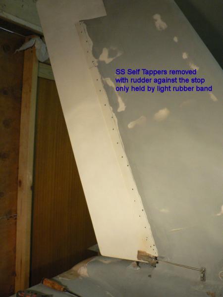
Rudder now will hold full right position using only a light rubber band to hold it against the stop.
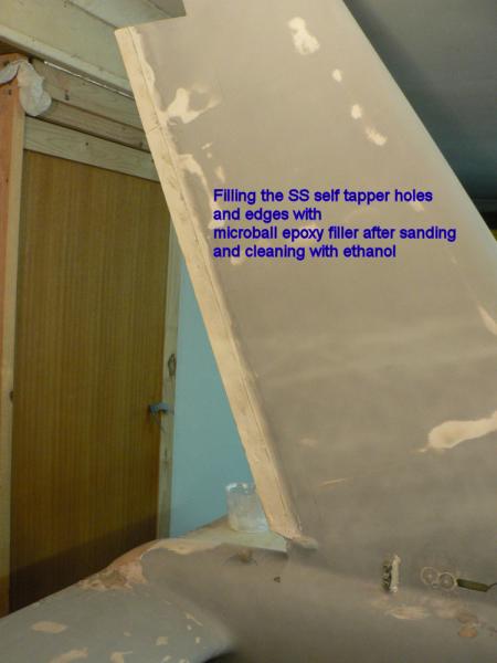
Removed the SS self tappers.
[ATTACH]6435.vB[/ATTACH][ATTACH]6436.vB[/ATTACH][ATTACH]6437.vB[/ATTACH][ATTACH]6438.vB[/ATTACH][ATTACH]6439.vB[/ATTACH]
Cleaned up around the self tapper holes using orbital sander and then ethanol.
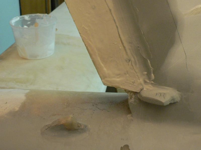
Mixed up micro-ball epoxy filler and filled self tapper holes and along leading edge and trailing edge of join of cover strip to vertical stabiliser.
[ATTACH]6440.vB[/ATTACH][ATTACH]6441.vB[/ATTACH][ATTACH]6442.vB[/ATTACH][ATTACH]6443.vB[/ATTACH][ATTACH]6444.vB[/ATTACH]
Allowed to cure with heater to keep the temp up. Winter is not quite over in our garage.
-
07-09-2008
Removed the strip over the gap by removing the SS self tappers used to hold it in place and prepared the surface for epoxy by removing the paint and the gel coat using an orbital sander with #240 grit sand paper.
Also removed the red seal cloth from back of fibre-glass cover strip material before sanding back the leading edge of it back to a thin edge to match up with vertical stabiliser surface.
Then cleaned up the surfaces with ethanol on a cotton rag.
Made up a batch of epoxy flock to attach strip to vertical stabiliser.
Applied flock to vertical stabiliser join area as well as the strip.
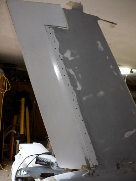
Used SS self tappers to hold strip in place and inserted additional SS self tappers to hold the strip firmly in place.
[ATTACH]6420.vB[/ATTACH][ATTACH]6421.vB[/ATTACH][ATTACH]6422.vB[/ATTACH][ATTACH]6423.vB[/ATTACH][ATTACH]6424.vB[/ATTACH]
Wiped off excess flock with rag soaked in ethanol.
Had to use heater to keep the temperature up for curing the epoxy.
-
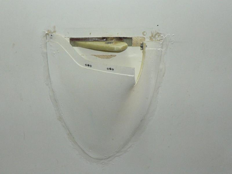
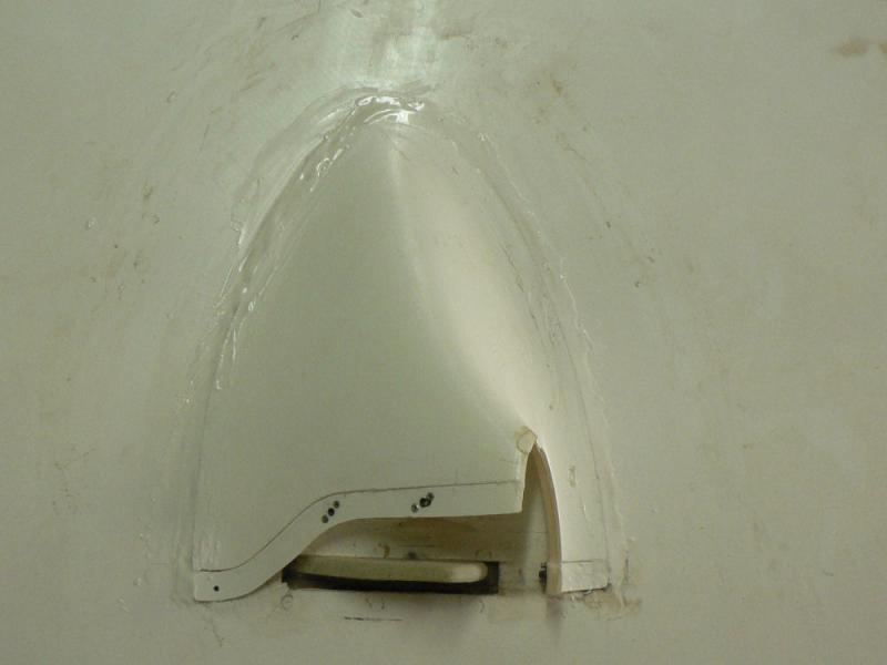
6-09-2008
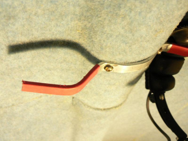
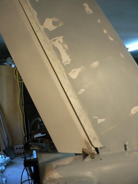
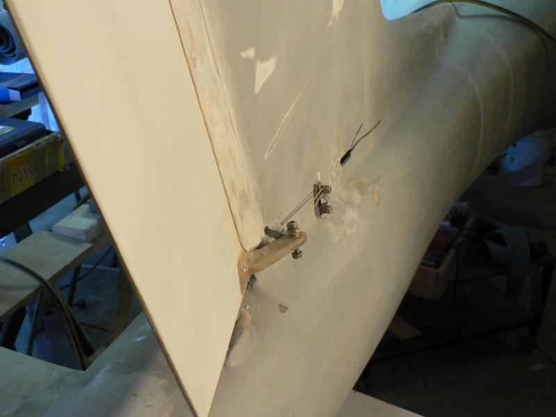
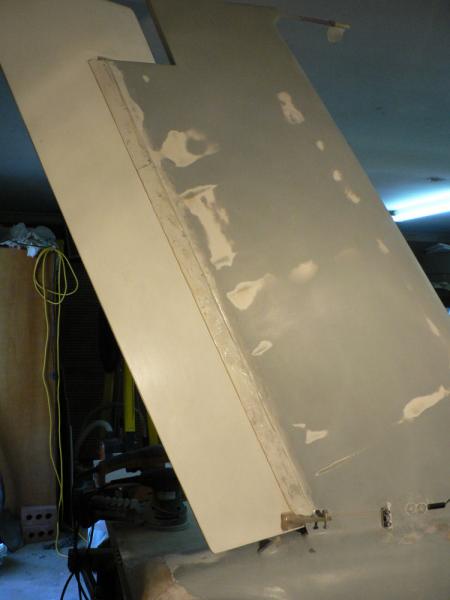
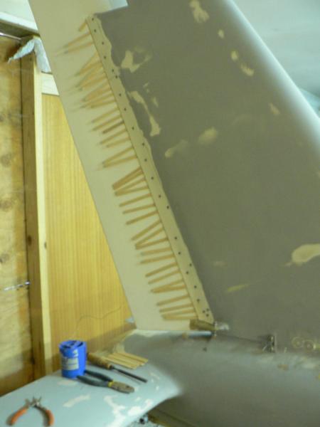
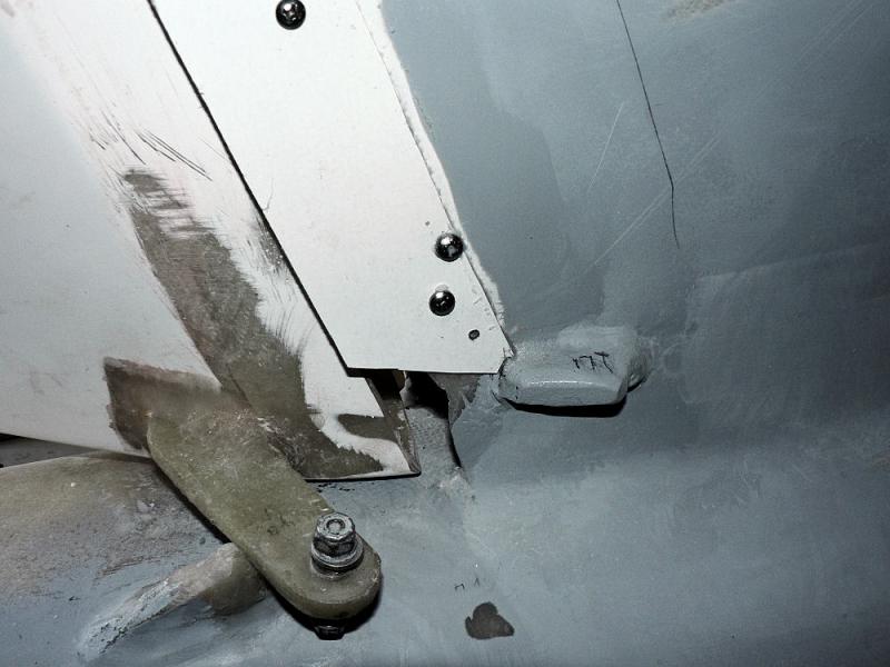
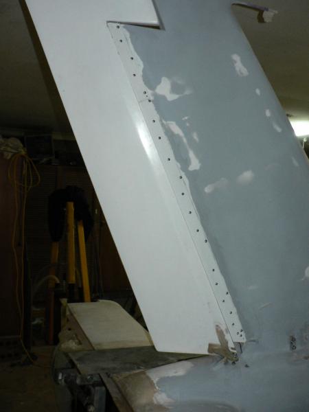
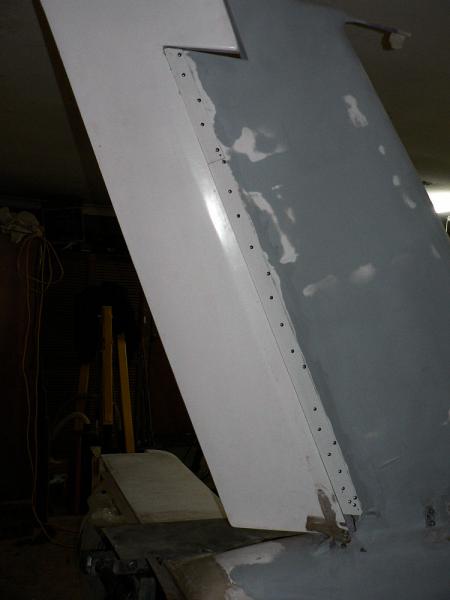
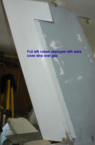
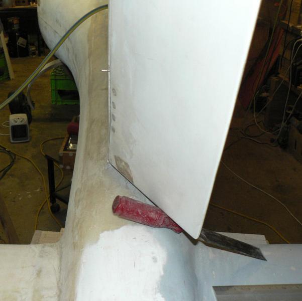
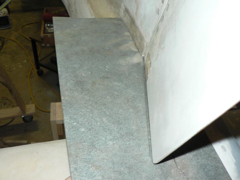
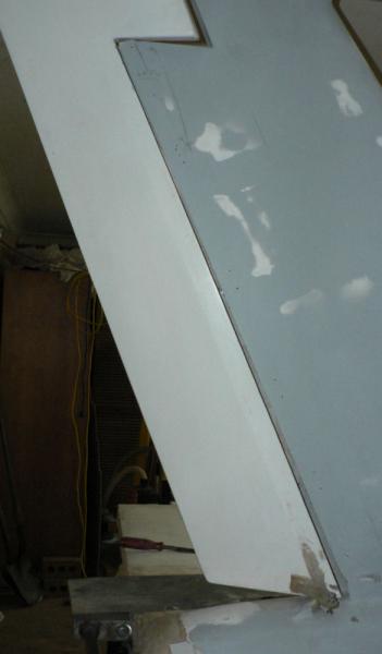
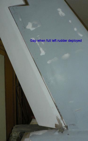
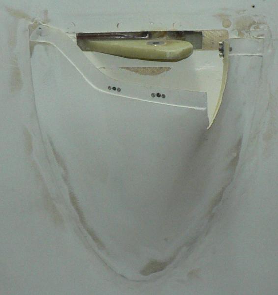
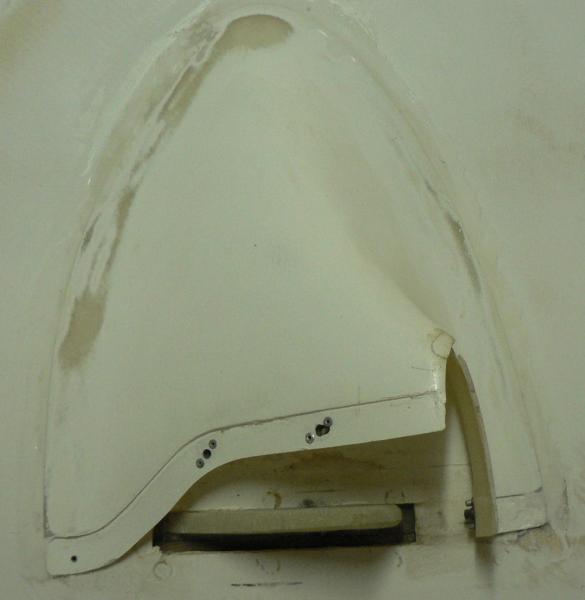
There is a gap between the rudder and the vertical stabiliser when full left rudder is deployed.
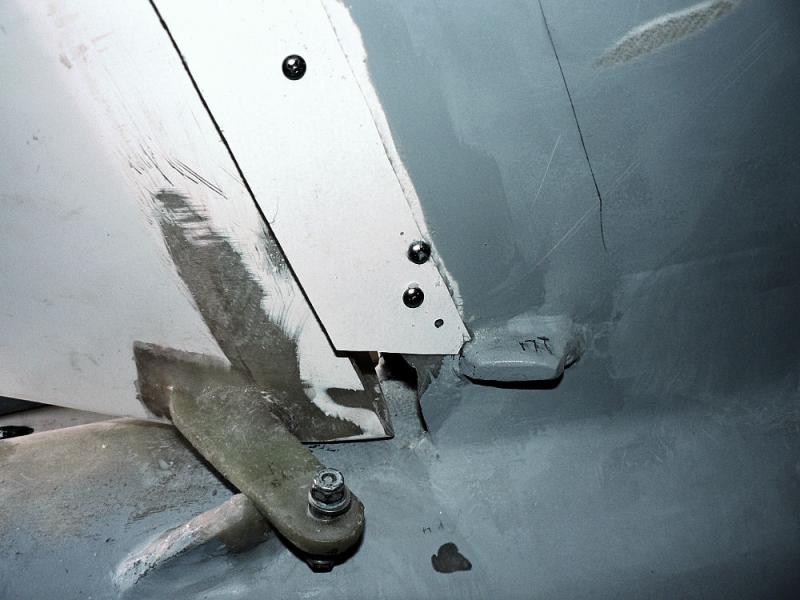
Prepared a strip of fibreglass to attach to RHS of AFT end of vertical stabiliser on opposite side of rudder hinges to close this gap when left rudder is fully deployed.
[ATTACH]6406.vB[/ATTACH][ATTACH]6407.vB[/ATTACH][ATTACH]6408.vB[/ATTACH][ATTACH]6409.vB[/ATTACH][ATTACH]6410.vB[/ATTACH]
The area under the strip will be stripped back to the fibreglass and the strip will be shaved down towards the leading edge and will be bent out slightly on its trailing edge after it is epoxied in place to clear the rudder when full right rudder is deployed.
[ATTACH]6411.vB[/ATTACH][ATTACH]6412.vB[/ATTACH][ATTACH]6413.vB[/ATTACH][ATTACH]6414.vB[/ATTACH][ATTACH]6415.vB[/ATTACH][ATTACH]6416.vB[/ATTACH]
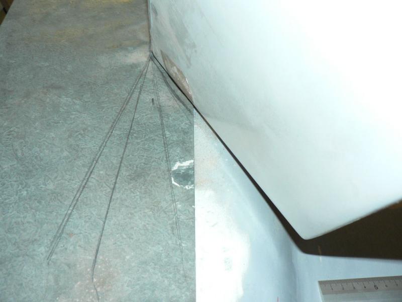
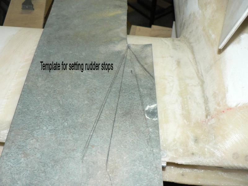
The last two pics show the gap with full left rudder before fitting the extra strip.
The rudder gap was aggravated by the necessity to move the rudder aft so that full right rudder could be deployed as the RHS of the leading edge of the rudder was being limited by the depth of the vertical stabiliser channel.
-
4-09-2008
Used a rotary random orbital sander with #240 grit self adhesive sandpaper with vent holes. The the sander is fitted with an exhaust bag to "collect" the dust.
Wore a face mask as essential equipment during any sanding.
[ATTACH]6394.vB[/ATTACH][ATTACH]6395.vB[/ATTACH][ATTACH]6396.vB[/ATTACH][ATTACH]6397.vB[/ATTACH][ATTACH]6398.vB[/ATTACH][ATTACH]6399.vB[/ATTACH]
The bogging undercoat will be essential to finish off these areas around the tail group and the strut fairings on the underside of the wings.
Any further machine sanding at this stage will be too deep on the existing fill.
-
3-09-2008
Changed my mind and decided to give the cable guide access patch another layer of epoxied microball fill.
Also filled around the edges of the strut fairings on ech wing.
All areas were prepared by sanding & cleaning up with acetone on a rage.
[ATTACH]6381.vB[/ATTACH][ATTACH]6382.vB[/ATTACH][ATTACH]6383.vB[/ATTACH][ATTACH]6384.vB[/ATTACH][ATTACH]6385.vB[/ATTACH][ATTACH]6386.vB[/ATTACH][ATTACH]6387.vB[/ATTACH]
Will have to keep looking at it because in the big fills the fill will keep flowing out until it has set.
-
One point I do remember of that first and only winch launched solo flight in the Nimbus with it's 18 or 19 metre wing span was thinking about three quarters of the way up the launch that the seat was too far back.
I spotted the seat adjustment on the RHS which you unclip and allow the seat to slide forward - the only trouble was that I was foregetting that the attitude was about a thirty degree climb or felt like it so as soon as I released the catch the seat with me on it immediately slid to it's most rearward setting.
Now I could not even touch the rudder pedals!
Shortly afterwards I released the winch cable after I had pushed the nose over releasing some tension on the winch wire and immediately heard the sound of the audible rising air indicator VSI so banked into a left turn then watched the ball on the slip and skid indicator slide from one side to the other without making any pauses near the middle. I eventually got the seat back in the right place and gave myself a rapid lesson in coordinating the rudder and aileron and eventually could keep the ball close to the middle.
I must have been extremely lucky that day because at the end of each 360 degree turn in that thermal (no matter where the ball was residing) which the aircraft had encountered as soon as we released from the winch despite my flying the a/c had gained about 1,000 feet in altitude. Four turns was enough to fly to Yanco and return and land after a very large circuit at over 100 knots with height to spare - there was a line up of members waiting to fly it!
There were many flights in less efficient a/c where I had to tap the altimeter lightly to see if we were gaining any height - as all glider pilots know basically a glider is always descending (loosing energy) when not being towed or pushed by an engine, a tug or a winch so the trick is to find air that is going up faster than your sink rate in that air.
Normally engine vibration in GA or RAAus A/c is enough to keep an altimeter moving that would stick for 20 feet or more in a glider w/o some encouragement.
Regards
-
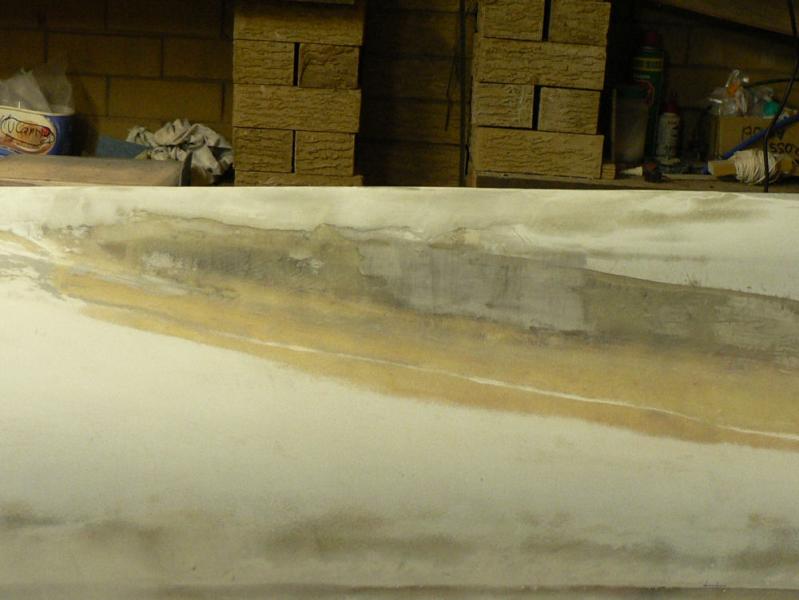
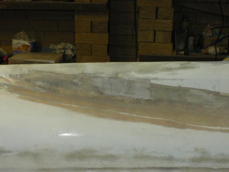
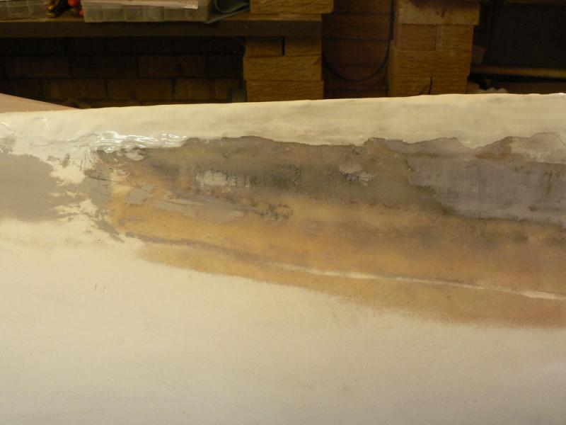
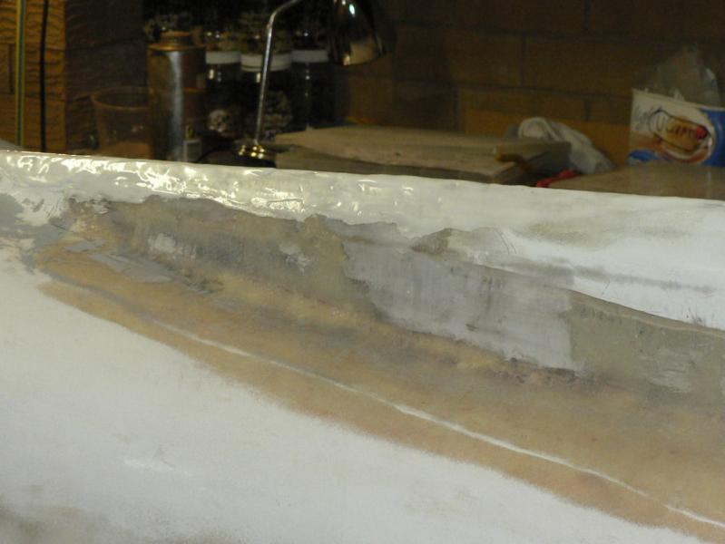
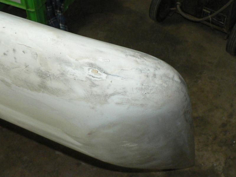
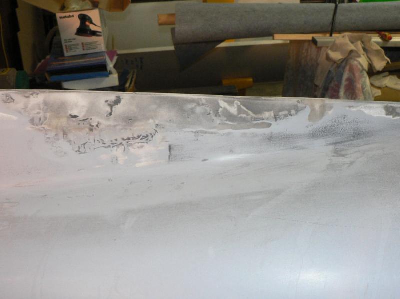
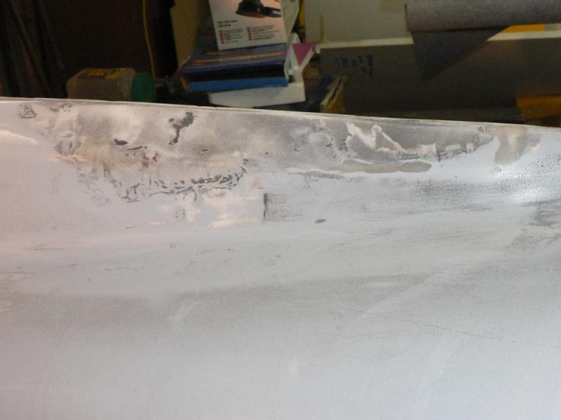
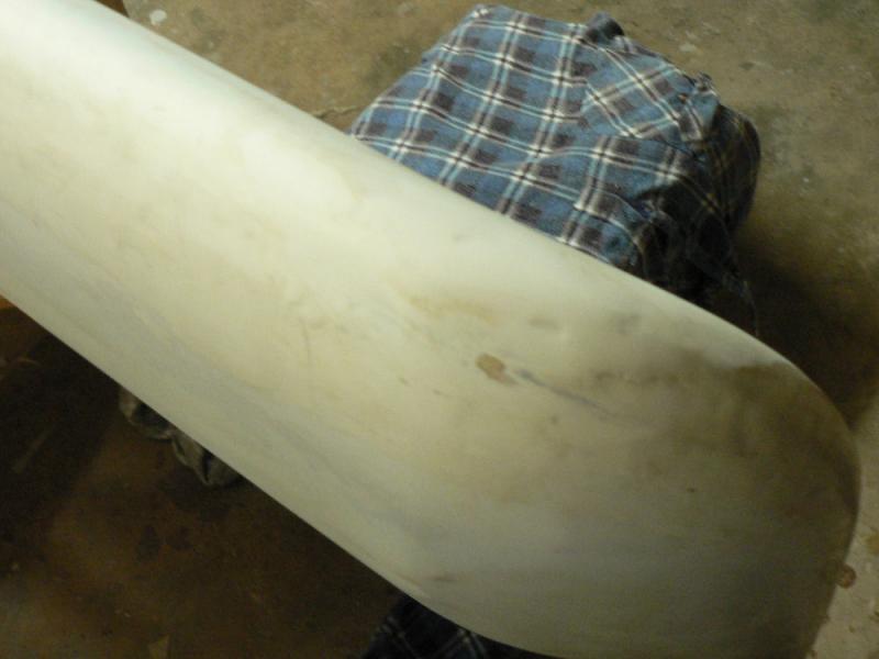
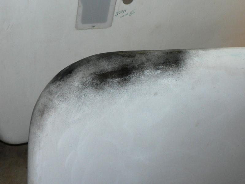
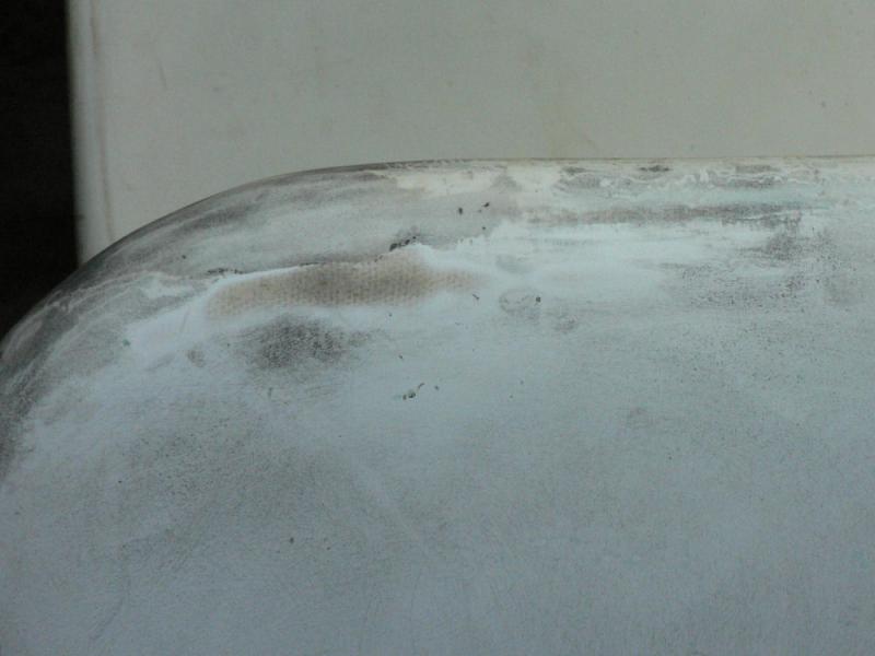
2-09-2008
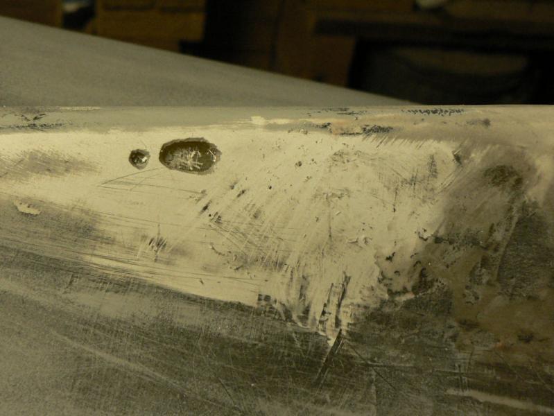
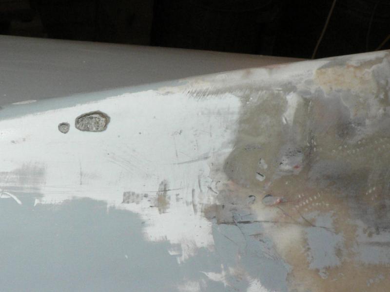
Continued to rub down cable access cover area on pilot side.
When enough done decided to remove spot spray from pressure pak can in low areas with a pocket knife. Found two of those spots were actually cavities in the gel coat with a paint like coat of gel coat across the top. Excavated them out and scored inside the cavity with the pocket knife to provide a key for eventual filling with epoxy micro-ball fill.
Rubbed and scraped some more then cleaned up both sides using Acetone on a thick cotton rag to get the last of the pressure pak paint off.
Rubbing back any more without applying more epoxy fill or paint undercoat would result in damaging the fibreglass.
Despite a couple of relatively deep low points decided both sides will fill OK with the two part bogging undercoat applied with the low pressure spray gun as some areas around the vertical stabiliser to fuselage join will require probably at least three or four layers of undercoat.
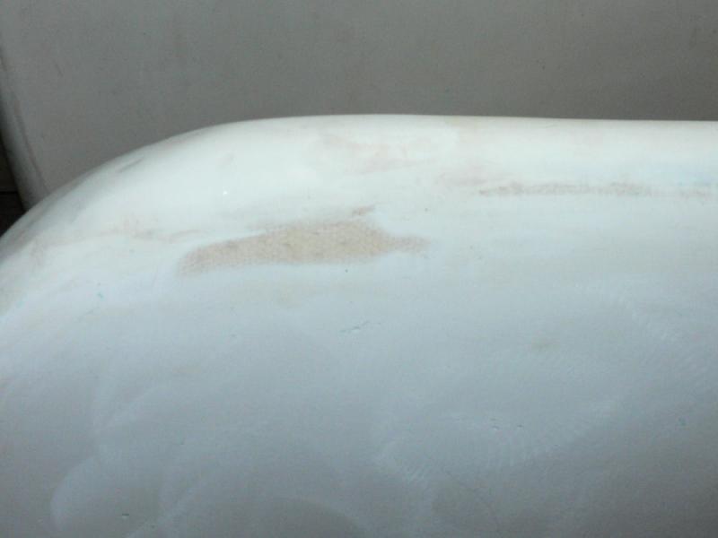
[ATTACH]6370.vB[/ATTACH][ATTACH]6371.vB[/ATTACH][ATTACH]6372.vB[/ATTACH][ATTACH]6373.vB[/ATTACH][ATTACH]6374.vB[/ATTACH]
The last pic is of the passenger side after cleaning up with acetone.
Could still partly fill those small depressions before applying the paint especially the two cavities in the gel coat.
-
More follow up from the owner of the LSA55.
His new parts from Jabiru arrived on Monday and he has returned the borrowed parts to their owner.
I quote below from his email.
I cut the old Jabiru oil filter open yesterday. Quite a lot of what looks like aluminium swarf. When the rivets broke, they rubbed between the rotor spindle and the aluminium distributor housing, so that's where that came from. It all seems to have stayed on the right side of the filter. Checked compression, all still on 175 /173 PSI (I don't have a leak down), valve settings all OK, and oil pressure hasn't changed.
-
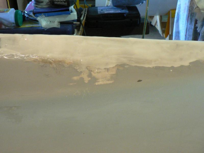
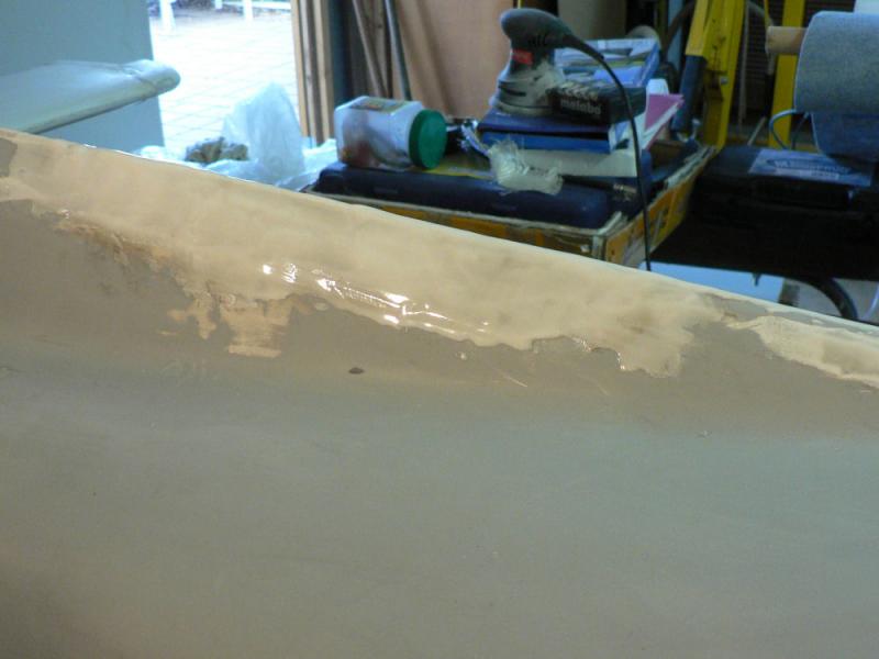
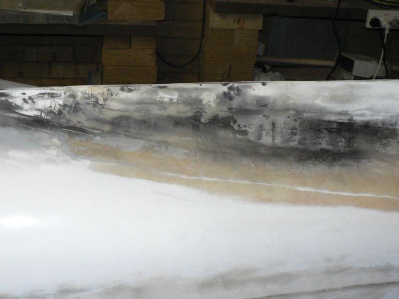
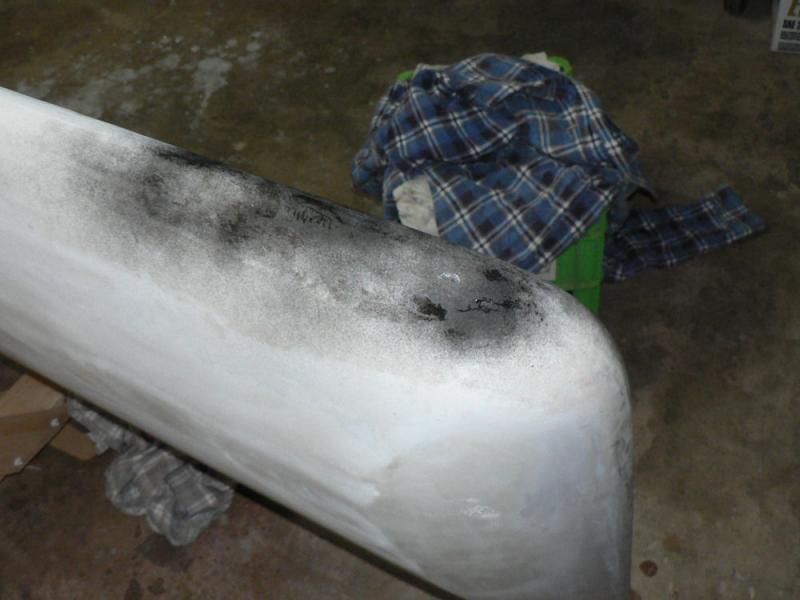
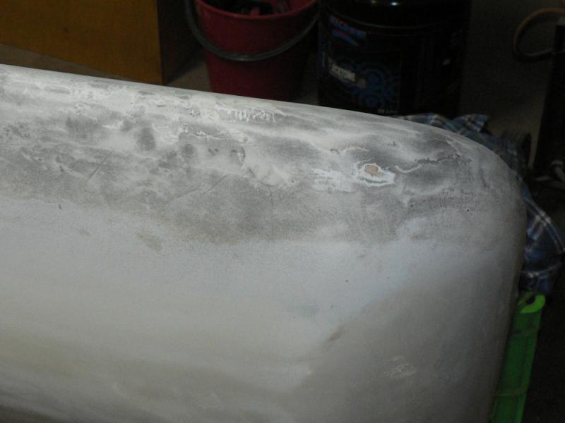
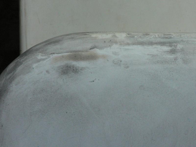
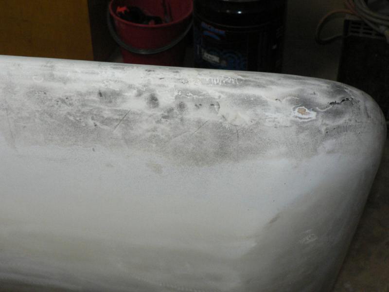
01-09-2008
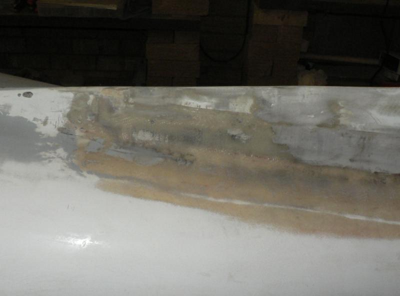
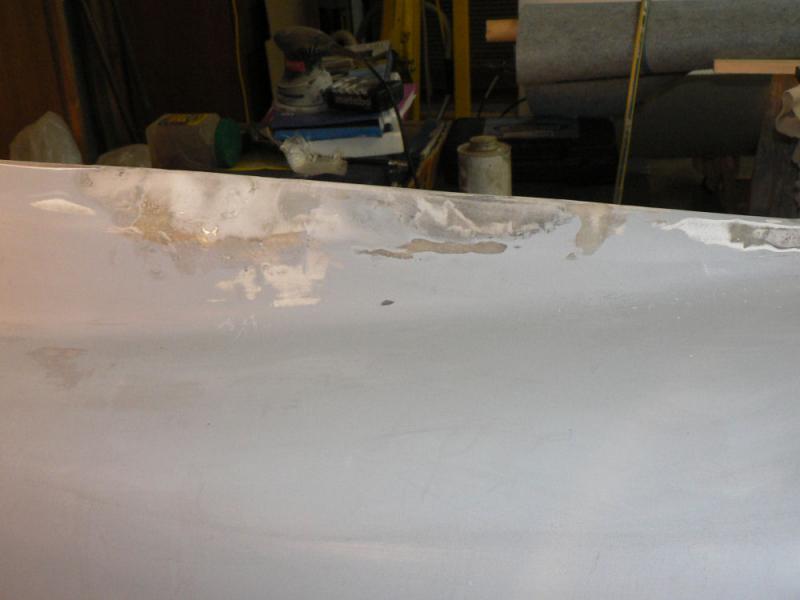
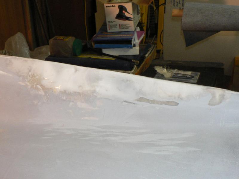
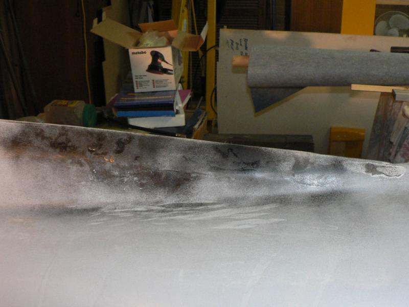
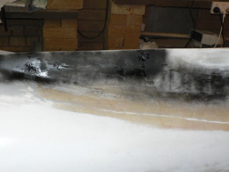
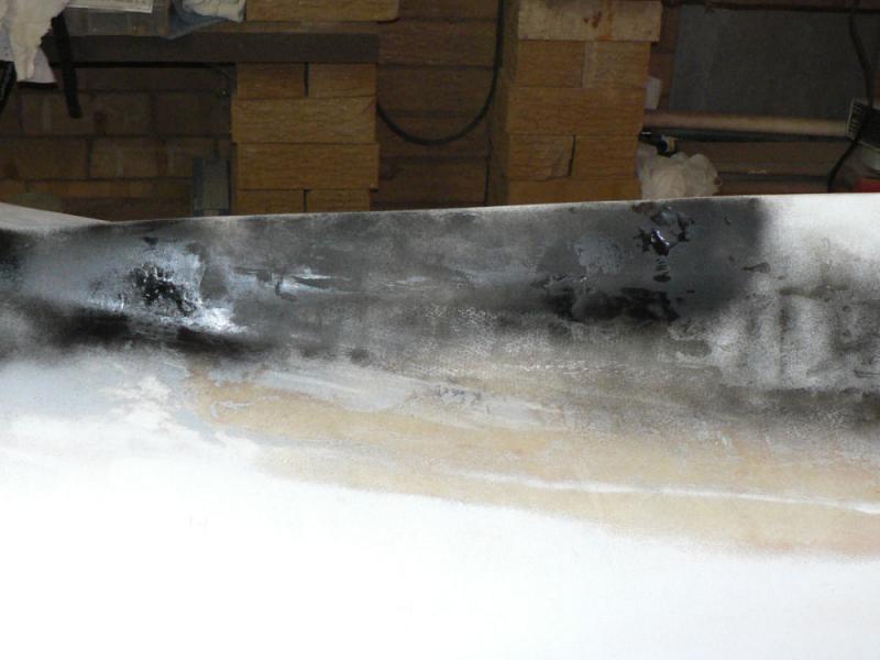
Used orbital sander with #400grit sandpaper to rub down the fill areas on the cable guide access holes and the wing fill for the damaged fill on the wing tip as done on the 9-08-2008.
After the rough fill was initially rubbed back with the orbital sander it was then sprayed lightly with black satin paint in a pressure pak.
It was then rubbed back some more by hand and using the orbital sander using the paint to expose high spots and low spots.
I only did one side of the top of the cable guide access fill as I had the spray can too close when applying the first lot and it also possibly appears to be a bit rougher than the other side. I will have another go at it tomorrow.
At this stage most of the photographed areas can probably be spot spray painted with the two part bogging undercoat and repeatedly rubbed back until it presents a smooth base for the final coat.
The pics show most of the fill surfaces after orbital sanding, then after a light coat of black paint, then after combinations of orbital sanding and hand sanding.
[ATTACH]6354.vB[/ATTACH][ATTACH]6355.vB[/ATTACH][ATTACH]6356.vB[/ATTACH][ATTACH]6357.vB[/ATTACH][ATTACH]6358.vB[/ATTACH][ATTACH]6359.vB[/ATTACH]
[ATTACH]6360.vB[/ATTACH][ATTACH]6361.vB[/ATTACH][ATTACH]6362.vB[/ATTACH][ATTACH]6363.vB[/ATTACH][ATTACH]6364.vB[/ATTACH][ATTACH]6365.vB[/ATTACH][ATTACH]6366.vB[/ATTACH][ATTACH]6367.vB[/ATTACH]
The waste had to be rubbed off with a rag periodically as it was confusing the issue getting ground into non sprayed areas. Maybe I should have used the air hose instead of the rag.
-
I know that Jabiru is also the name of a small NT town near the junction of the Kakadu Highway and the Arnhem Highway almost due East of Darwin.
So if those aeroplanes with Kangaroos on their tails have featured the name of this town on one of it's aircraft I was wondering when their organisation will notice Carrathool in NSW which is probably about the same size as Jabiru and is also usually the home of many of the big red plains kangaroos on the surrounding properties.
Not holding my breath.
Regards
-
ROM I am not surprised to hear that. There do seem to be a number of communication failures in the organisations involved.
It is sounding like the old flywheel using 1/4" set screws and with no dowels story to me.
-
There is no manual mixture control on the Jabiru motor so the only normal option is to ground the ignition system with the "mag switches". The throttle stop is supposed to be set so that the 2200 motor idles at 800 rpm.
If that does not work, like I saw at a recent fly in (not on a Jabiru motor) then the normal remaining option is to shut off the fuel with the main fuel valve and that can take some minutes before the carburettor fuel level is low enough to stop the motor.
Maybe you could also possibly flood the warm motor with the choke and stop it if the throttle stop had been set correctly. This would be quicker than waiting for the carburettor to empty but probably not very good for the motor.
-
As of yesterday,Saturday, the LSA55 is back home in its Northern home having flown there on borrowed parts so that it had two working distributors. The owner was still waiting on parts from Bundaberg but he was advised that they had already been despatched.
-
Hi ROM
For JL I was not really up to the Nimbus or Janus either only having one flight in each but I can still vividly remember the flights as being absolutely magical compared to what I was used to flying at the time. The only trouble is that the vivid memory of two flights is becoming like the "not so vivid" memory of one flight being unable to distinguish between the check flight in the two seater and the flight in the Nimbus.
The scale of the operation here at LEETON nowadays is nothing like that at Horsham at this stage of the game but I am envious of the situation you are mostly enjoying there.
After letting my GFA ticket lapse, I did my RAAus conversion at Griffith with the Griffith Aero Club which had just started to cross hire a Jab LSA at the time. Griffith Aero Club was basically a GA club owning a number of GA planes with a number of others available for hire. As my GFA tickets had lapsed I did not get credit for the 8 hours and 192 hours flying experience that I had respectively in GA and gliders
I had driven over there 60 km to start and waited around for most of the day to get a flight and after signing away the first $2,000 if I stacked the plane, joined the club paying all the RAAus stuff at the time and was eventually asked if I wanted a TIF. I said NO. Start the instructional flights now, today! So I got my first flight in a Jab with the instructor eventually telling me quite a few months later not to keep landing on the numbers! I must have been missing them most of the time up 'till then!
I was surprised to find out later that I was the first student in that factory built Jab which had about five hours on the clock when I started. I think that I might also have been the first RAAus (ctually AUF) student of that instructor, Ben Jones, at the time. Ben has since been hired by REX and joined their training program which I think he has now completed. After being used to aircraft like L13 Blaniks and Is 28s flying the Jab at a stable speed was difficult and took me a quite while to be happy with it - hence the eventual J160 kit decision supposedly a longer A/C but it did have larger tail feathers than the earlier Jabs.
After getting my Certificate and the establishment of Wally Rudin in Narrandera only about 25 km away, I now do my flying, at least until I complete my J160, at Narrandera in Wally's J230c. I found the J230c much nicer to fly than the smaller Jab LSA. I still have my $2,000.
The Griffith club gained from many of the local GA pilots wanting to get their RAAus conversions but this also resulted in a loss of utilisation of the GA fleet. So the Griffith Aero Club was on the verge of extinction early this year with the loss of the CFI and two other Intructors to other more lucrative aerial pursuits. The local economy was and is still drastically affected by very large reductions in the annual water allocations to the local irrigation farmers who are the backbone of the local economy in Griffith as well as Leeton. These reductions have been getting worse each year for the last five or six years.
I think the Griffith Aero Club has rationalised it's A/C fleet, now has a Tecnam available for students and the original Jabiru owner now has a RAAus instructor rating and one of the local AG plane operators has returned to be GA CFI at the club. The CFI is the one who has built the fishing boat that occupied a hanger at YGTH for many years - the boat is still on the field and will eventually be based in Port Fairy.
Murrumbidgee (Narrandera) Aero Club has the advantage of not owning anything except a small Club house that was destroyed in a storm and rebuilt with the insurance money. A number of the members own their own A/C GA and mostly RAAus which are parked in the council owned hanger a legacy of the RAAF training program during WWII. The Club also gets the advantage of most of Wally's students at Narrandera as members during their training at least.
Long enough
Regards
-
Hi JL
I only remember one female club member off a farm in Wamoon!
I used to fly club sail-planes but basically around Ltn. Plenty of good outlanding sites. Finished up with about 200 hours with only two forced outlandings but a number of other outlandings for training with aerotows etc.
I did not compete solo in the state or international competitions but did so once as a team member club pilot sharing one of the club two seaters usually with a novice in the passenger seat in the state comps.
Longest flight was in a Club Libelle for a 300k Diamond Goal LTN, Junee, West Wyalong, Ltn for a duration of 6 hours. Must have been the slowest 300 k on record but the time was not important then, just getting around as that was my only major achievement after the Silver C.
A test flight and solo in a visiting Nimbus and Janus showed me what a near top performance Sailplane was like to fly - just incredible compared to our main club gliders the Club Libelle 1/32, L13 Blanik 1/28, Es52 Mk IV Kookaburra maybe 1/25. Although we eventually bought others which I flew as well plus a number of visiting sailplanes.
Gave it away with pressure fom family and health.
The empty nest and retirement fixed the family pressure eventually and a couple of St Vincents sessions has fixed the health bit.
So then took up RAAus flying in a Jab at YGTH followed by purchasing J160 kit a year or so later which I am still in the process of assembling.
-
To Juliet LIma
That sounds like a vaguely familiar glider rego to me from my past life memories!
Are you a past visitor to Leeton?
Regards
J160 Kit#14 various with Photos
in Jabiru
Posted
20-08-2008
Used the "W" terminal on the oil pressure sensor to run a lead back to a new LED on the panel.
Installed the new LED below the other LEDs on the panel and ran a lead back to the "instrument bus" to supply the power when it is operational.
Once it was wired up, tested it as follows.
On turning on the main switch the low pressure LED turned on.
On operating the starter motor, once the oil pressure came up on the pressure gauge the LED light went out.
[ATTACH]6540.vB[/ATTACH][ATTACH]6541.vB[/ATTACH]
Once the starter motor was released and the pressure dropped the warning "LED" was illuminated again until the main switch was turned off.:thumb_up: