

Ross
-
Posts
729 -
Joined
-
Last visited
Content Type
Profiles
Forums
Gallery
Downloads
Blogs
Events
Store
Aircraft
Resources
Tutorials
Articles
Classifieds
Movies
Books
Community Map
Quizzes
Posts posted by Ross
-
-
26-05-2008
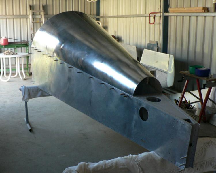
Spent most of yesterday afternoon printing selected parts of the new J160 construction manual from the Jabiru web site, a big improvement on my original version. I also printed all the relevant engine manuals for my non hydraulic valve lifter engine 22A 2200 cc 4 cylinder engine #1906.
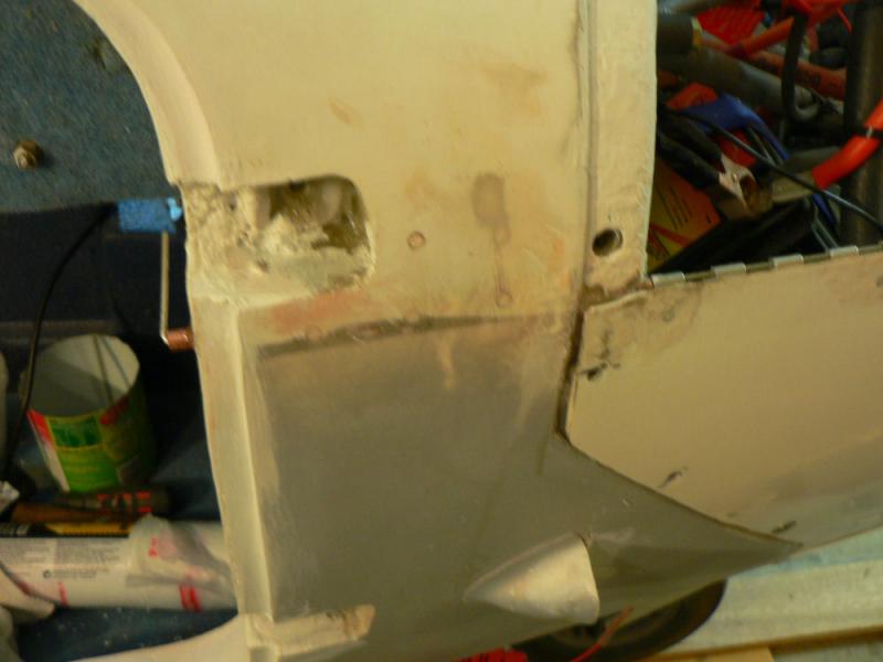
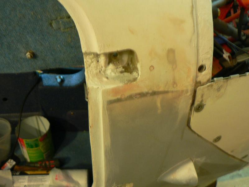
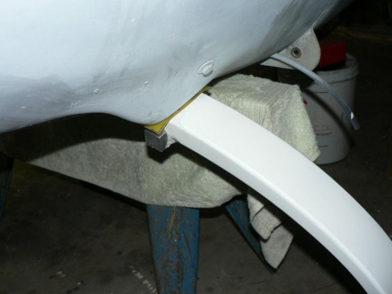
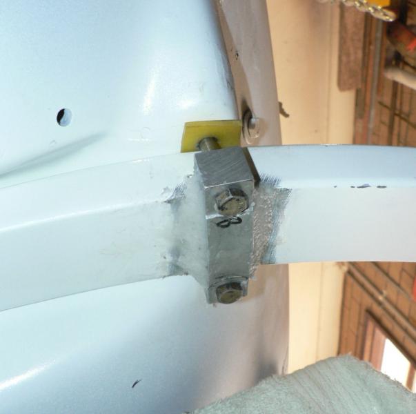
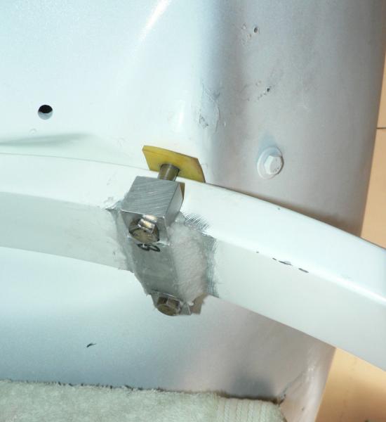
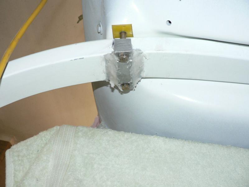
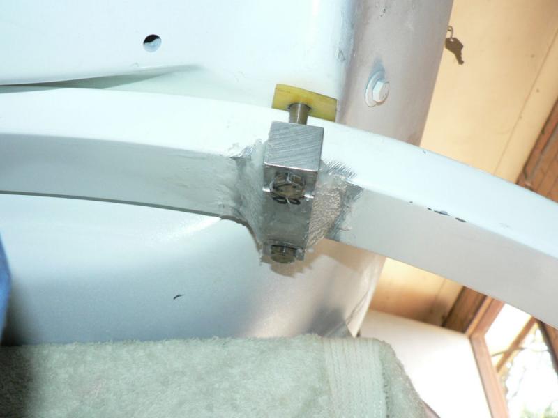
Got some more information from the new J160 construction manual on on the cowl installation and setting up the engine thrust line.
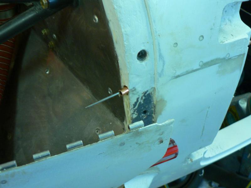
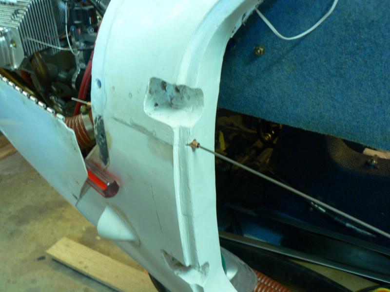
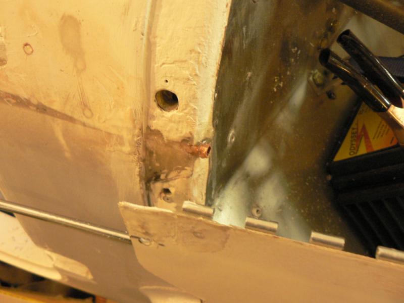
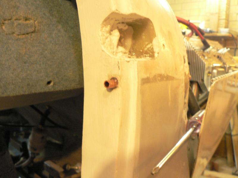
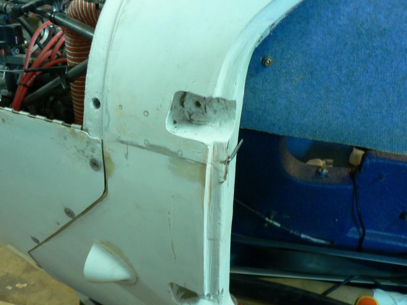
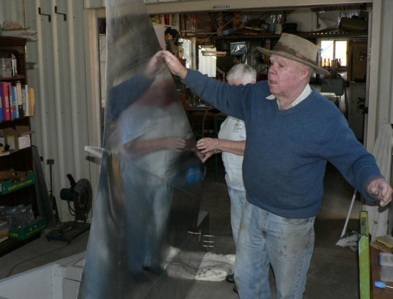
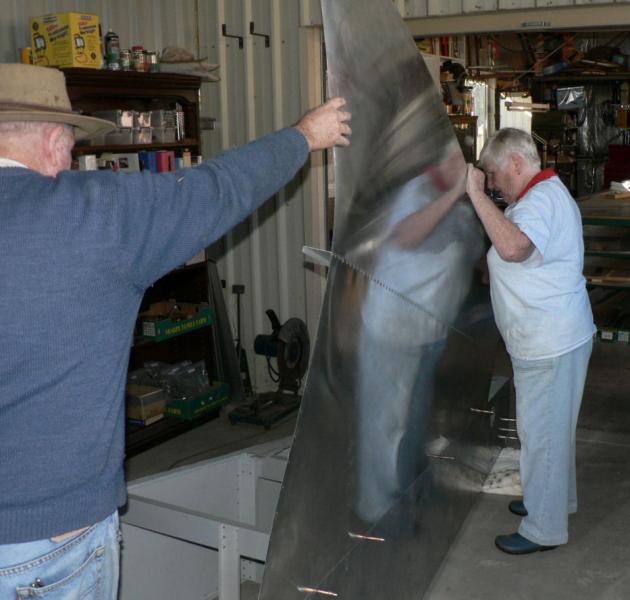
Drilled out the existing pin holes for cowl piano hinge pins to 1/4" clearance, inserted guide copper tubing and quick set araldited it in place then dressed it off with a cutting wheel.
[ATTACH]5750.vB[/ATTACH][ATTACH]5751.vB[/ATTACH][ATTACH]5752.vB[/ATTACH][ATTACH]5753.vB[/ATTACH][ATTACH]5754.vB[/ATTACH][ATTACH]5755.vB[/ATTACH][ATTACH]5756.vB[/ATTACH]
Then the pins were tried again for an easy fit.
The piano hinges still need to be removed and epoxied in place and riveted.
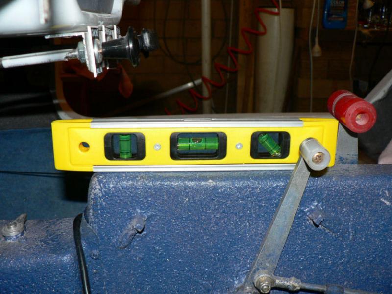
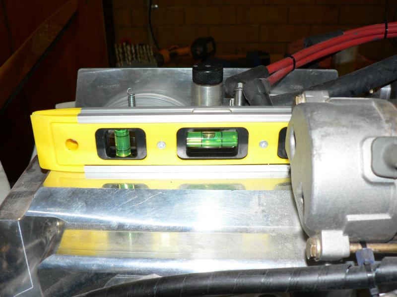
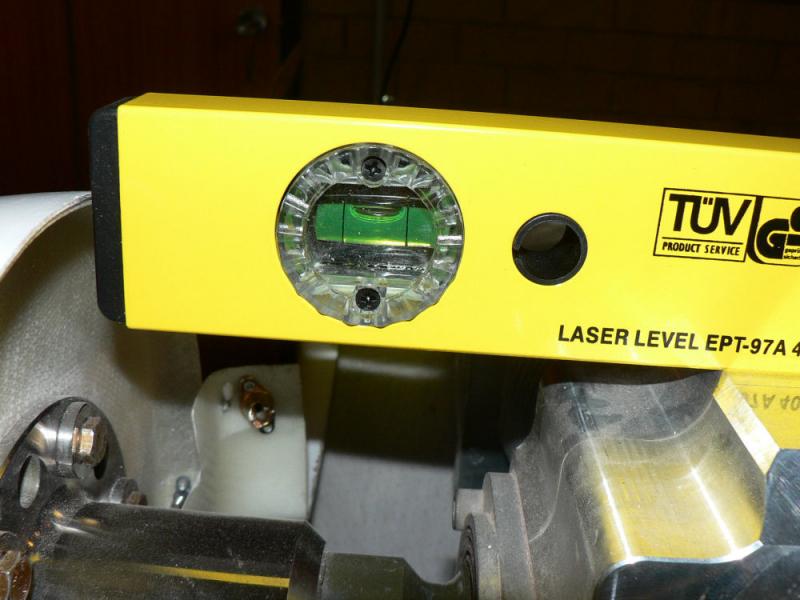
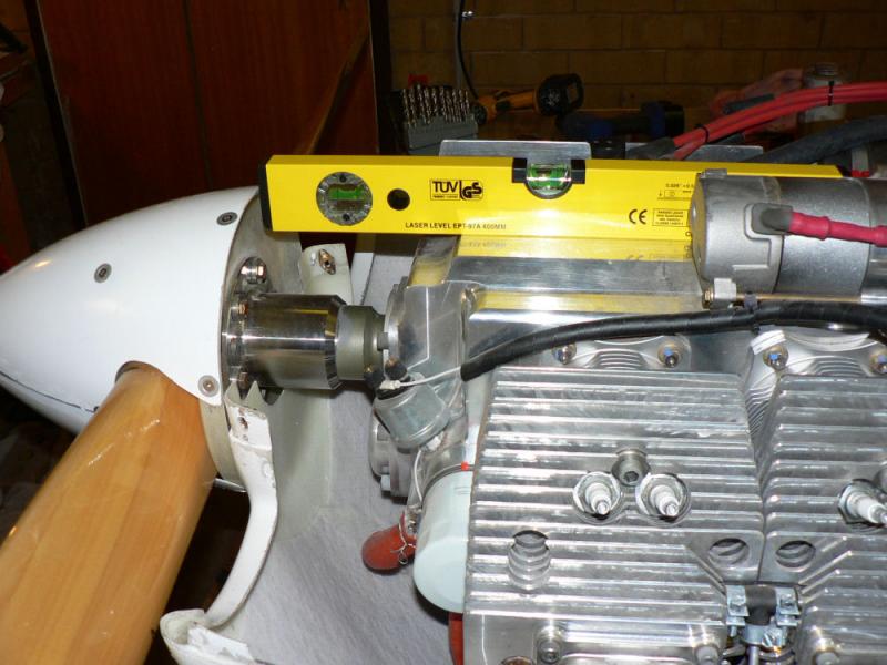
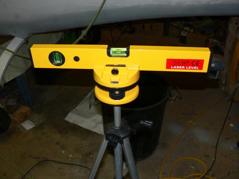
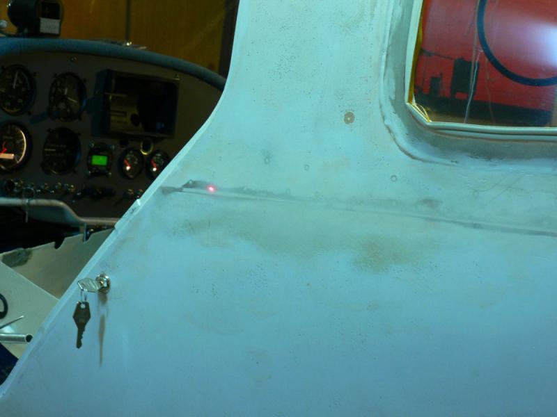
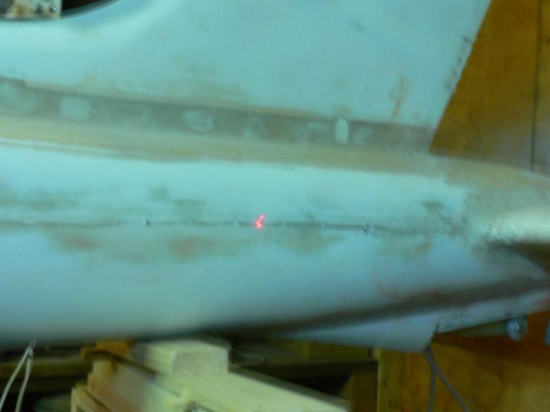
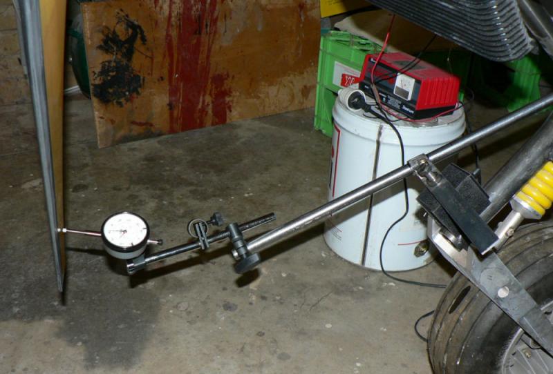
A small laser level was used to trial the setting up of the engine thrust line.
The last three pics show the laser level being used to level the hull based on the hull join line. You can see the red laser dot on the hull line in the last two pics.
The laser dot seems to affect the digital camera focus.
The top of the engine housing should be parallel with the hull join line.
As the cabin was not yet level in the lateral plane it was not completed due to one wheel being still off the ground.
[ATTACH]5757.vB[/ATTACH][ATTACH]5758.vB[/ATTACH][ATTACH]5759.vB[/ATTACH][ATTACH]5760.vB[/ATTACH][ATTACH]5761.vB[/ATTACH][ATTACH]5762.vB[/ATTACH][ATTACH]5763.vB[/ATTACH][ATTACH]5764.vB[/ATTACH]
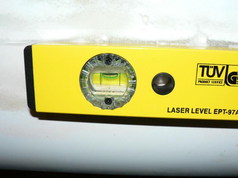
But the laser level appears to be accurate enough for the job if set up properly in the X and Y horizontal planes.
The laser level was checked for accuracy over the length of the aeroplane from the back of a door to about the back end of the elevator. It appears to have less than about 1 mm error.

-
I thought the very rough rule of thumb was to add about 2% airspeed for every 1000 ft AMSL.
So 9.5x2 % = 18%
130 I.A.S x 1.18 = Approx.153 knots T.A.S.at 9,500 AMSL
and it could be worse than this depending on QNH
-
15-05-2008
Been a bit crook for a while. But did a bit in between over the last couple of days.
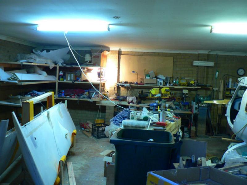
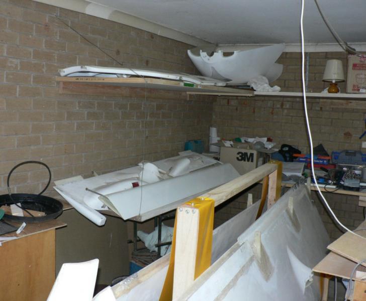
Put another layer of shelves in, including a narrow one over the saw bench - note the engine box acting as the first moveable bench has had its extension removed and is now in the corner under the shelves. Cardboard boxes are gradually being emptied onto shelves.
Put another power box near the corner to give another work area. It will get the battery charging away from the fibre glassing weighing and mixing area, a bit late.
The garbage bin is full and more is on the concrete pavers outside the carport.
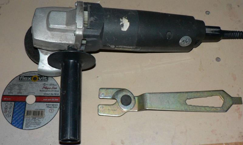
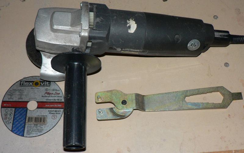
Found an adjustable tool at Mitre 10 to replace my lost one. It will undo the head on my angle grinder or anything else that requires that type of tool.
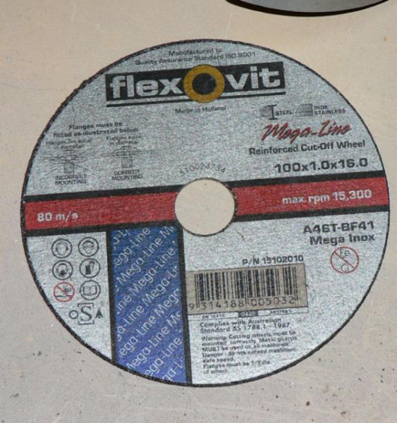
I just discovered the cut off wheel which has been around for a while but a lot better than I was used to.
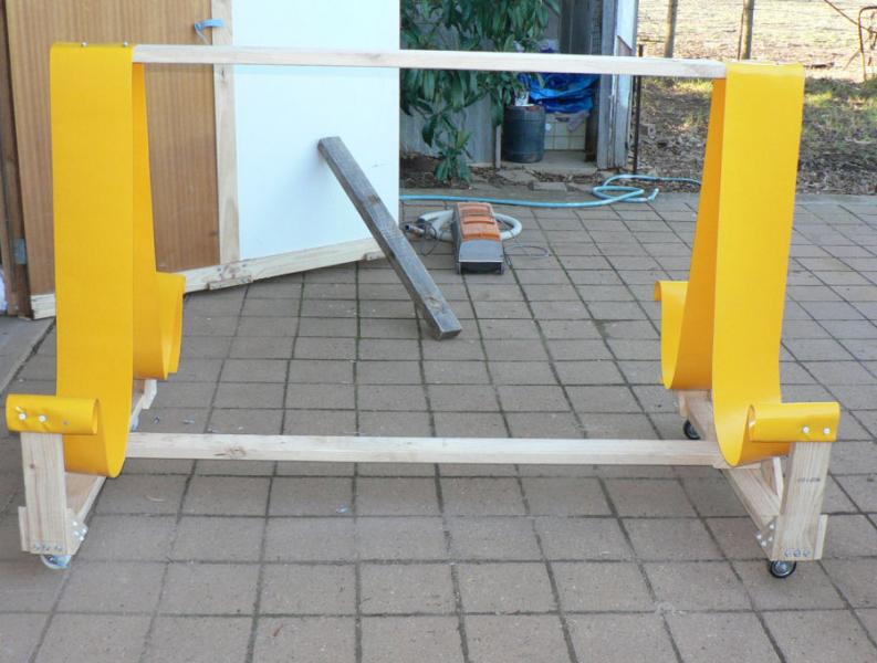
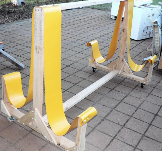
The wing stand is on castors and is very easily moved.
[ATTACH]5719.vB[/ATTACH][ATTACH]5720.vB[/ATTACH][ATTACH]5721.vB[/ATTACH][ATTACH]5722.vB[/ATTACH][ATTACH]5723.vB[/ATTACH][ATTACH]5724.vB[/ATTACH]
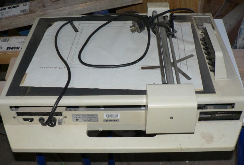
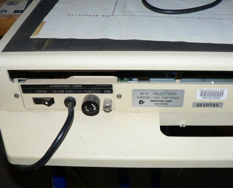
The MP1000 Graphtec Multi Pen Plotter with a RS-232 C interface is going on the scrap heap. If you don't know what an RS-232 interface is don't bother reading any more! It is not a variety of Parallel interface. It was used like another printer on my system at the time.
It was still working fine when I last used it but it needs programs to be written to drive it. I used to use a variety of Fortran to produce simple maps and some simple 3D drawings based on a data file containing all coordinates the X,Y,Z directions. I have lost all literature on it and have forgotten the detail.
If anybody wants it yell now. First in best dressed.
Obviously it has at least one stepper motor under the cover.
Apparently some years ago I had already chucked out all the pens and the pen holders that I had made to suit it.
-
11-05-2008
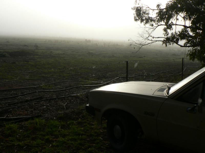
This morning was different with the sun eventually burning off a fog. Discovered that my camera time was still on daylight saving time; duh it doesn't automatically change.
[ATTACH]5690.vB[/ATTACH][ATTACH]5691.vB[/ATTACH][ATTACH]5692.vB[/ATTACH][ATTACH]5693.vB[/ATTACH]
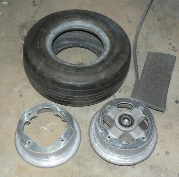
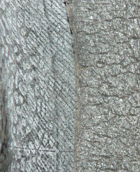
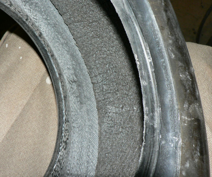
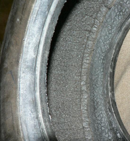
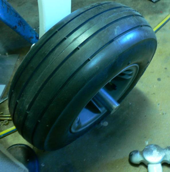
Removed a main UC wheel and inserted some sponge 100 mm wide in the tyre. Once I got the tyre off it was far easier than I envisaged. As the foam was readily compressible allowed an extra 20 or 30 mm length and pushed it in and seated well. No adhesive used. The 6 inch tyres have an outside circumference of about 44 inches or 1120 mm.
[ATTACH]5694.vB[/ATTACH][ATTACH]5695.vB[/ATTACH][ATTACH]5696.vB[/ATTACH][ATTACH]5697.vB[/ATTACH][ATTACH]5698.vB[/ATTACH]
Inserted the tube and partly inflated it to reduce the risk of pinching by the assembly process. Assembled the split rims to the tyre and remounted on the main UC. It is obviously out of balance once mounted on the axle and its own bearings.
About sunset my wife said don't put tea leaves down the sink it blocks the grease trap and it overflows!!!
Turns out the sump pump in the sump and 15 feet further down the line was not doing its job and the gauzed in area was now full of overflow from the sump as I had just back flushed the pool sand filter into the sump!
-
It always seemed a big ask to me for a carburettor to work reliably over a range of throttle settings particularly if there is a disturbance like a bend in the air intake immediately upstream of the carby.
In another life I used to work with some instrument fitters who were responsible for looking after and installing flow meters in gas and liquid piplelines.
For a flow meter orifice to work reliably the orifices had to be placed sometthing like at least either 5 or ten pipe diameters downstream from any radical disturbance like a change in section diameter or a bend or an elbow so that normal velocity distributions across the pipe diameter would occur at all normal flow rates (throttle settings).
I cannot remember the multiple, it was many years ago. Nowadays, there are new electronic style flow meters that do not cause the pressure drop associated with orifice plates.
There are Australian Standards for the design of orifice plate installations which might be food for thought in this discussion.
A reduction in pipe diameter or straightening vanes (like a cross) can be effective in straightening out stream flow after an offending disturbance if you cannot get enough straight pipe to do the job but preferably not at the price of increased pressure drop. The straightening vanes could also increase the risk of icing.
I notice in some other engines there is an emphasis on ensuring that there is a straight air entrance into the carburettor reducing the variation that must occur if the entrance does not come from a straight pipe.
A help in this situation might be that aero engines are normally only asked to run over a small range of revs/min.
-
10-05-2008
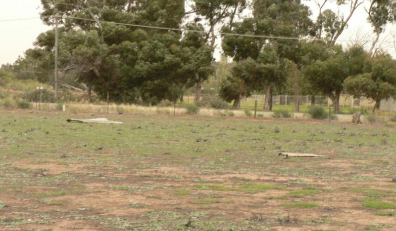
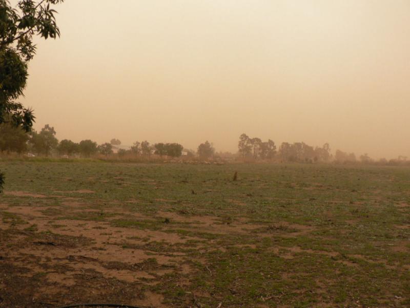
The morning sky was a bit unusual this morning in Leeton being more yellow than normal.
[ATTACH]5687.vB[/ATTACH]
Did more work on reducing the stuff that lives on the floor by chopping up what had been a train set made for the kids probably back in the seventies. You can see the outline of the track on the box.
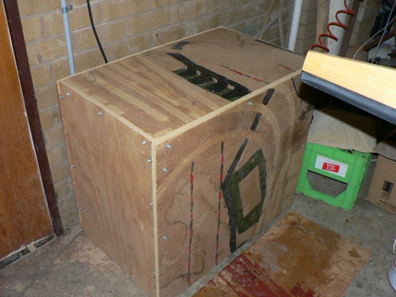
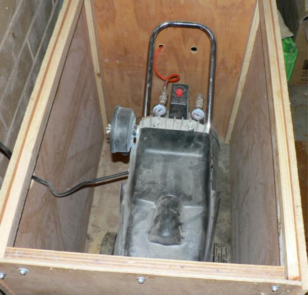
Made up a box for the air compressor - cuts the noise substantially might be even better if I can find some sound absorbent tiles to glue or sit inside it.
[ATTACH]5688.vB[/ATTACH][ATTACH]5689.vB[/ATTACH]
Managed to get hold of some 100 mm wide foam rubber to use as tyre liners to reduce the risk from "cat heads". I hope I don't ever encounter any "castor oil plants" as they have burrs like giant cat heads.
I will put at least couple more door type shelves in the carport on Monday. That should get all the stuff off the floor and able to be covered.
-
09-05-2009
I decided that I was in imminent danger of falling over too much stuff all over the place in my carport and possibly breaking a leg!
So have started to reduce the clutter by making a wing stand instead of using the big box from Jabiru. I have also managed to get rid of a refridgerator and an old washing machine that was trapped in one corner of the carport and was almost impossible to get to.
The yellow plastic is from the local tarp manufacturer and are left over strips from making tarps for railway wheat trucks. The length needs adjusting to get the wings approximately level.
[ATTACH]5683.vB[/ATTACH][ATTACH]5684.vB[/ATTACH][ATTACH]5685.vB[/ATTACH][ATTACH]5686.vB[/ATTACH]
Purchased a couple of extra doors to use as shelves to add to the old door that was already tying up a couple of saw horses.
So those three were were attached to a wall with timber bearers screwed into the brickwork. Loaded that up with all the bits like fairings, ailerons, flaps, elevator. The doors are there now above it together with the struts although they were added after the pic was taken.
Still more work to do there to make more working space and then actually do some work on the aeroplane.
-
Magellan 296
Title should say Garmin 296
I noticed a Jab I think reporting on a return trip from Darwin cooked its external GPS antenna as it was sitting on the top of the panel when the ac was parked in the midday sun and presumably self destructed with the heat. I think that antenna on along lead has a built in amplifier which would make it more susceptible to excess heat damage.
However that Garmin 296 GPS continued to work once the standard short plug in antenna replaced the one on the long lead.
In my fibreglass J160 construction I have managed to get the Garmin 296 in the panel which has an Aluminium face and have the short plug in antenna work satisfactorily.
It must be rotated and standing up to switch it on (make the connections in the socket). So it does require a little head room so the antenna can be vertical. But it does work in my AC parked in a brick garage provided I have the personal access door in the garage wall in front open to view.
When I flew the LSA 55 Jab at Griffith I sat an old hand held Magellan 320 GPS on the passenger seat which worked fine but the Garmin 296 seems to be a far better signal getter than the old hand held when sat next to each other on a table.
-
03-05-2008
Noted that the Jabiru constructor's manual and service bulletins were updated on 1st May 2008.
The newer versions of the Jabiru constructor's manual have gone through a transition with a higher quality of photos and English text with more precise explanation.
Parcel arrived from Bundaberg West yesterday afternoon with the flame proof version of the cabin heater but not the different designed muff & hoses for the larger dia tubes. There was also a set of modified outer disk pad holders that are more user friendly than the originals.
[ATTACH]5643.vB[/ATTACH]
It appears that the brakes have been increased from one slave each side to two for the later J160. I am not sure of that not having looked very hard at the new manuals yet but I would not object to more effective brakes especially as you virtually have no steering under very heavy braking.
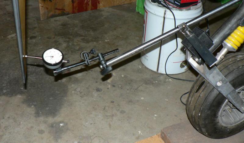
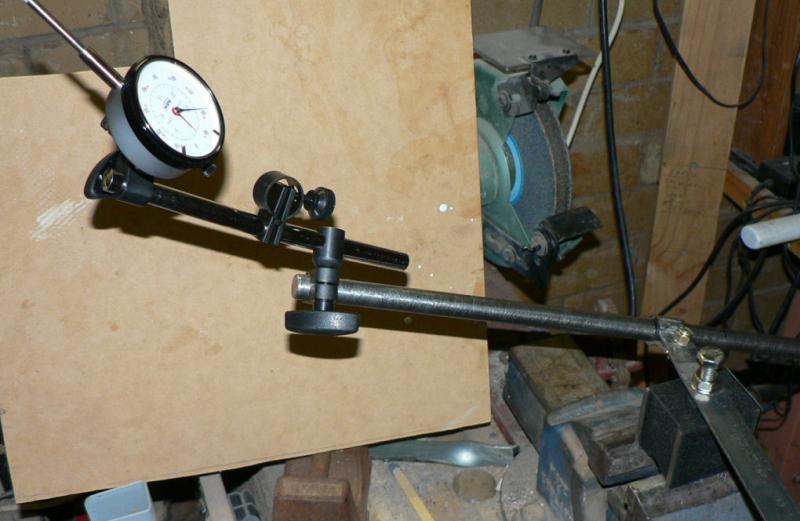
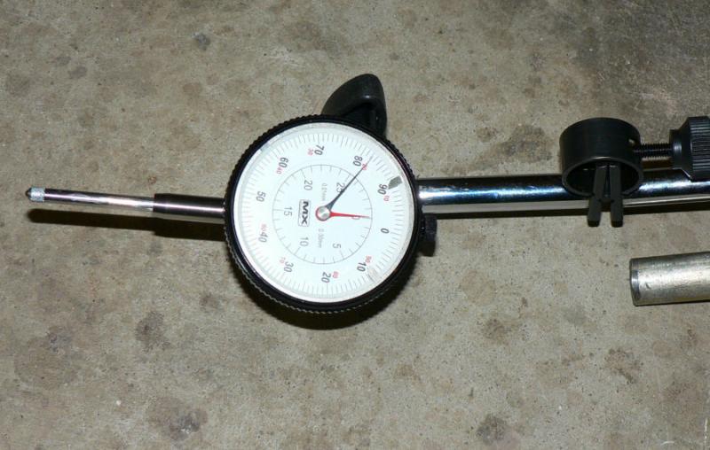
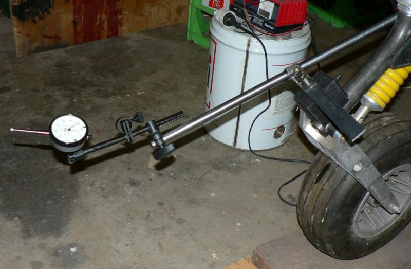
Today, tidied up the mount for the dial indicator by replacing the solid ).625" dia solid bar with a piece of hydraulic tubing same od. with a 0.5" bore, a fair bit lighter on the magnetic base.
[ATTACH]5644.vB[/ATTACH][ATTACH]5645.vB[/ATTACH]New version next[ATTACH]5646.vB[/ATTACH][ATTACH]5647.vB[/ATTACH]
Cut the head off the bolt screwed into the top of the magnetic chuck.
Put the clamp for the rod closer to the centre of the magnetic chuck. So bent up a large washer under the head of the clamp bolt making it easier to adjust with one spanner.
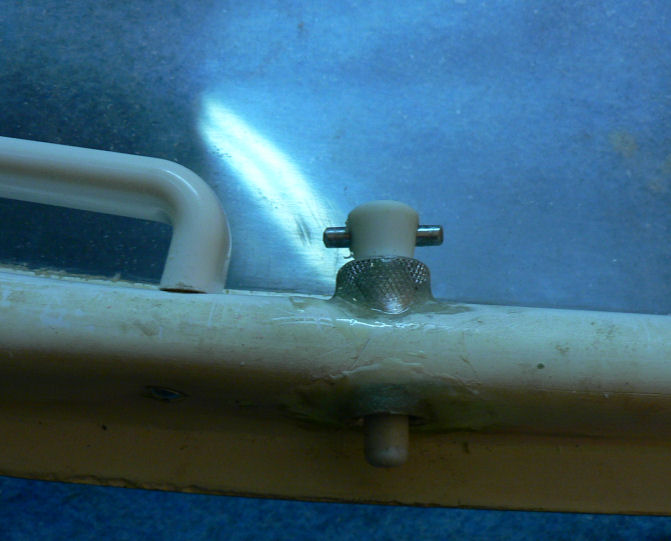
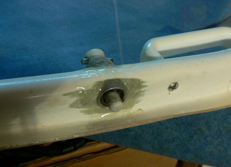
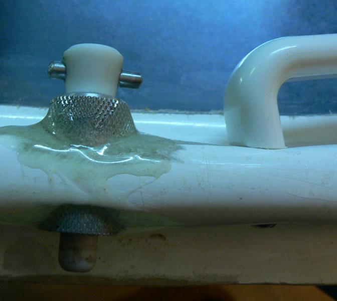
Drilled across through through the top of the dowels for the top door catches and Super-glued a couple of inserts into the handles to make them easier to pull out.
May be a good idea to apply some flock around the inserts later on.
[ATTACH]5648.vB[/ATTACH][ATTACH]5649.vB[/ATTACH][ATTACH]5650.vB[/ATTACH][ATTACH]5651.vB[/ATTACH][ATTACH]5652.vB[/ATTACH]
Put all the Jabiru applicable service bulletins in one four (4) ring binder.
-
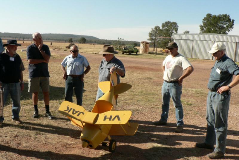
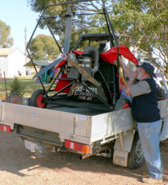
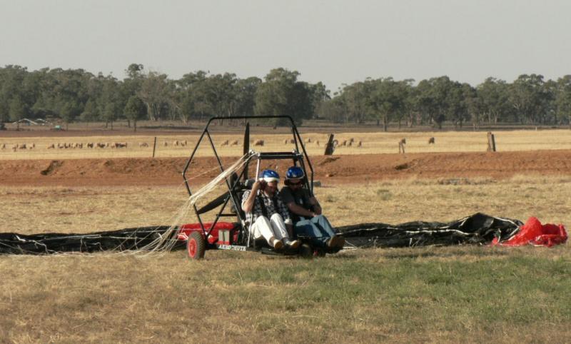
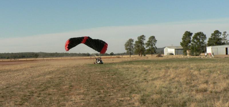
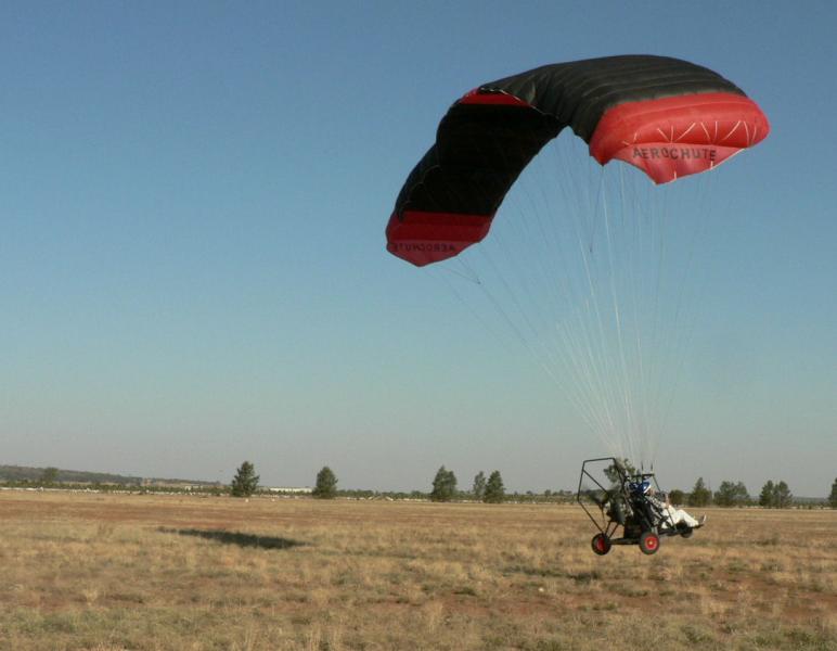
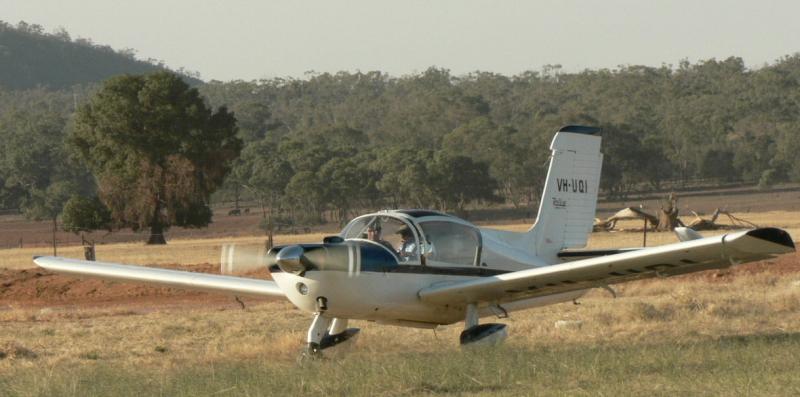
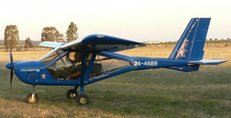
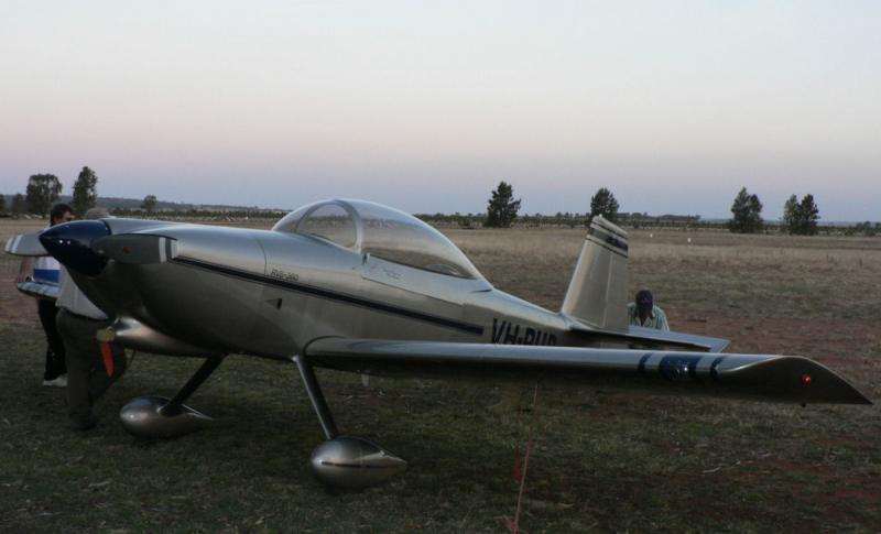
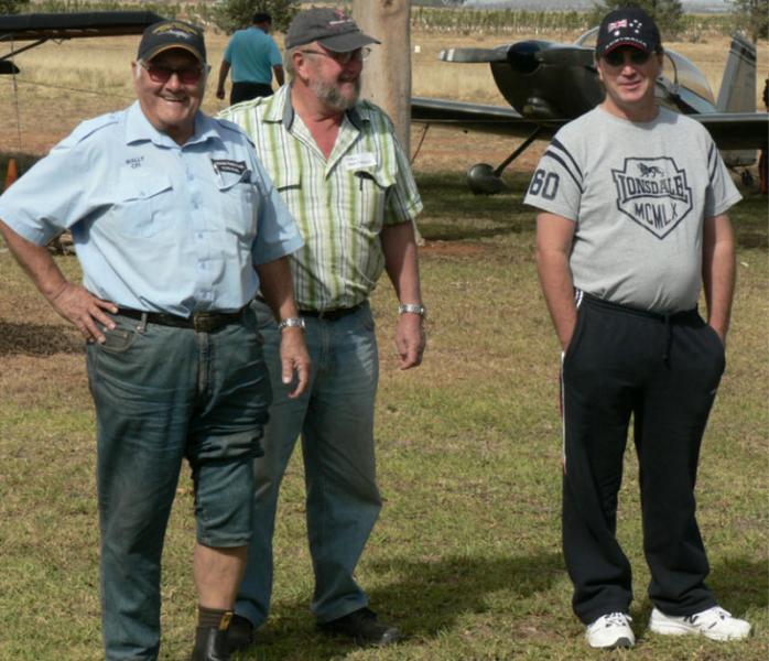
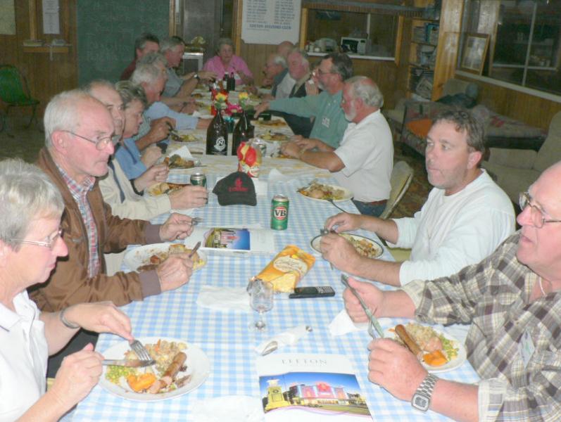
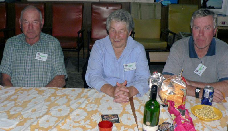
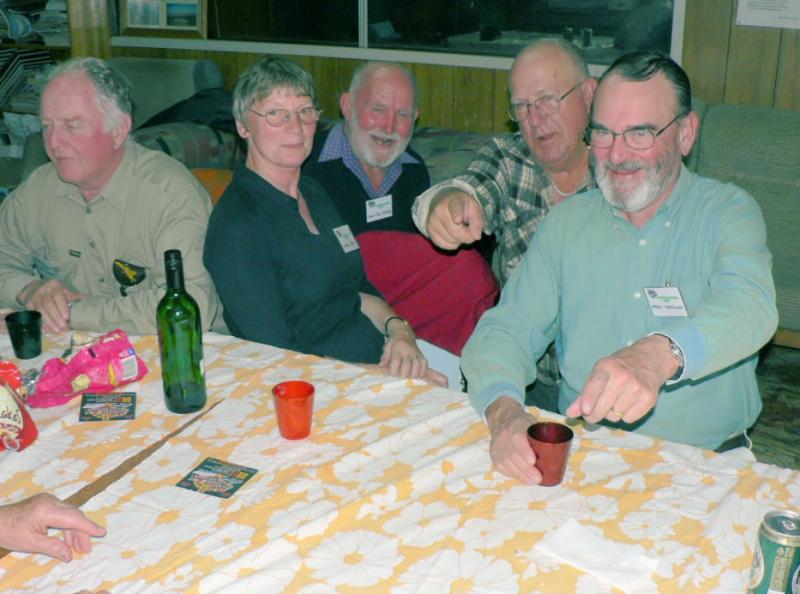
Leeton Aviators (about 90 miles west of Temora) hosted a fly-in despite the competition from Temora and the uncertain weather.
A feature of the days was the friendly atmosphere and the meals served up by the senior ladies of club members.
An Aerochute enthusiast provided some entertainment when after a circuit the two ignition switches would not stop the motor. Deprived of its' fuel, it eventually succumbed. The fault was found and rectified. There was as a piece of foreign material between the contacts in one of the two switches.
[ATTACH]5631.vB[/ATTACH][ATTACH]5611.vB[/ATTACH][ATTACH]5612.vB[/ATTACH][ATTACH]5613.vB[/ATTACH][ATTACH]5614.vB[/ATTACH][ATTACH]5615.vB[/ATTACH][ATTACH]5616.vB[/ATTACH][ATTACH]5617.vB[/ATTACH]
[ATTACH]5618.vB[/ATTACH][ATTACH]5619.vB[/ATTACH][ATTACH]5620.vB[/ATTACH][ATTACH]5621.vB[/ATTACH][ATTACH]5622.vB[/ATTACH][ATTACH]5623.vB[/ATTACH][ATTACH]5624.vB[/ATTACH][ATTACH]5625.vB[/ATTACH]
[ATTACH]5626.vB[/ATTACH][ATTACH]5627.vB[/ATTACH][ATTACH]5628.vB[/ATTACH][ATTACH]5629.vB[/ATTACH][ATTACH]5630.vB[/ATTACH][ATTACH]5632.vB[/ATTACH][ATTACH]5633.vB[/ATTACH][ATTACH]5634.vB[/ATTACH]
[ATTACH]5635.vB[/ATTACH][ATTACH]5636.vB[/ATTACH][ATTACH]5637.vB[/ATTACH][ATTACH]5638.vB[/ATTACH][ATTACH]5639.vB[/ATTACH][ATTACH]5640.vB[/ATTACH]
Everybody who stood still was provided with a name tag by Pat White which made it a bit easier for most to get acquainted.
Although some of the touch and goes from the local fields did not bother which was a pity. I tried to get the tags in the photos but probably need a slightly darker tag so they don't glare if the flash is used.
Sunday saw the arrival of some light rain showers passing across the field from the west. I recorded 12 mm at my place on the North edge of Leeton. So the remaining AC were stowed in the hanger with John Russell's plane displaying a set of folded wings. It took him about 5 minutes to fold them! Two of the pilots flying from Nev's place at Corbie hill managed to fly back to their hangers and returned by road. John Herrmann's RV-8 (I think) ended up close to the middle of the hanger surrounded by other planes). Norm Harrison made sure he had his usal position just inside the northern doorway of the hanger.
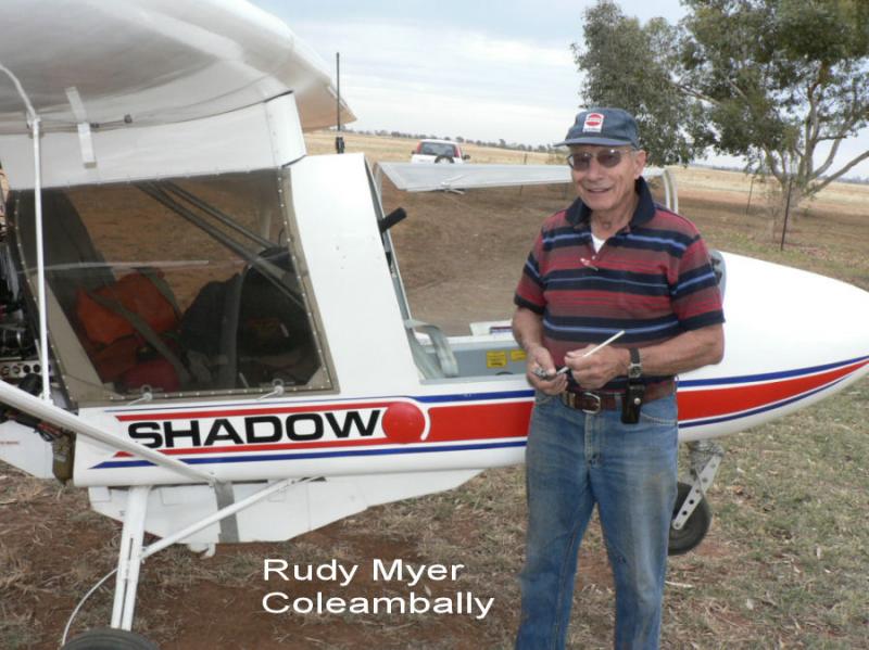
Postscript today: Rudy Meyers' Shadow engine is US for the moment :raise_eyebrow:'till Nev White can make up a new part and assemble it.
-
01-05-2008
Well the Brobenah fly at Leeton in is over with a reasonable attendance despite the weather and the Temora circus.
I am waiting on some material from Bundaberg which I ordered in the middle of last week.
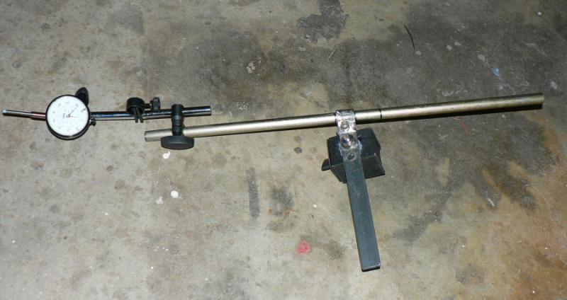
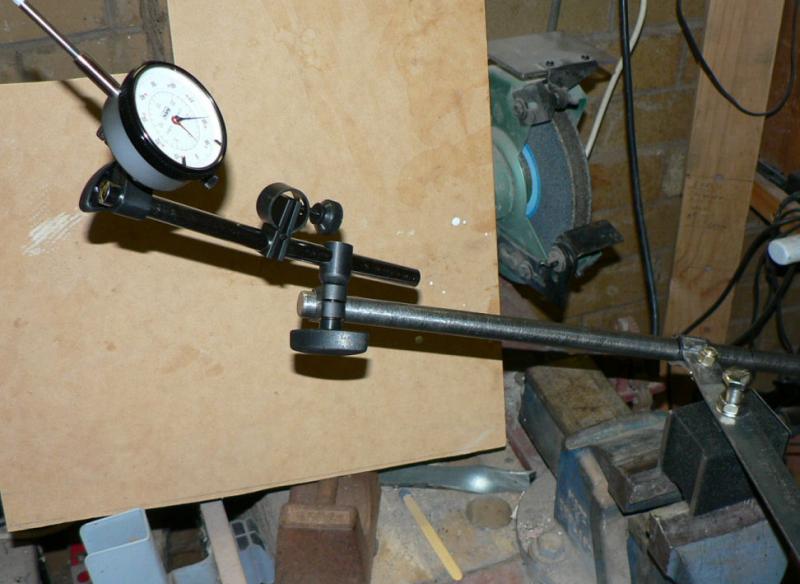
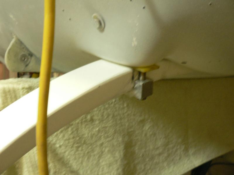
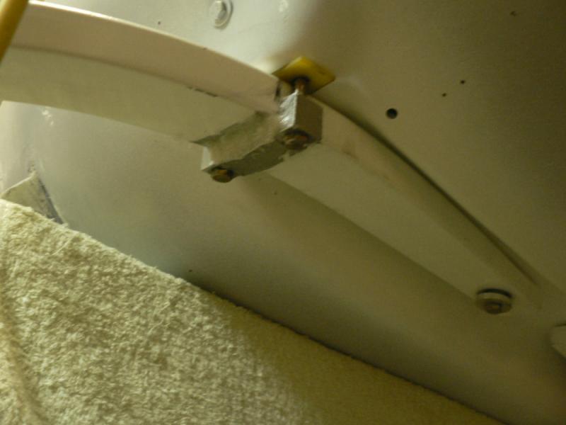
A dial indicater with magnetic base ordered from interstate turned up earlier in the week . Today I modified it by adding a longer arm so that it could be mounted on the front UC leg of the J160 to check out the prop layup. I bit early yet for this job, supposed to be after paint.
I could not find any bright 16 mm dia steel in Leeton so had to settle for black 16 mm with mill scale so Warren cleaned it up on his lathe and I made a clamp for the rod and assembled the modified parts to make it work.
I discovered that the magnetic base had a shallow 10 mm 1.5 pitch coarse threaded hole in a box of Aluminium and managed to strip part of that thread. Loctite is a fairly useful material.
[ATTACH]5608.vB[/ATTACH][ATTACH]5609.vB[/ATTACH][ATTACH]5610.vB[/ATTACH]
The extended leg og the main support shaft allows for a bit of counterbalance to the weight of the shaft and the dial gauge.
Later on I will probably cut off the head of the fully threaded SS bolt and make it a permanent fixture on the magnetic base.
-
24-04-2008
Managed to get a severe chest infection last week and ended up in hospital for most of last week due to my stupidity in not wearing a face mask while doing some drilling.
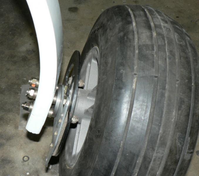
Today did a bit with Warren interrupting his Sonex project. We used his milling machine to cut some 2 mm deep channels in the back of the outside aluminium disk brake pad holders for my J160.
This made it possible to anchor a heat proof nut there and make it easier to install and service the brake pads which the current design of the disk brake achieves.
It will also slightly increase the gap between the nut and the inner side of the aluminium rim of the main UC wheel.
Brought the parts home and used some 2 part Loctite 3805 tolerant to 150 degrees C to stick the nut to the back of the channel. Held the nut in tension against the Loctite 3805 until it set which was proved by removing the bolts from the nuts with a ring spanner.
It is very messy because the Loctite was very dry and extremely hard to get out of the tube but had the advantage that none of it ended up on the thread of the bolts used to keep the tension on the nut.
[ATTACH]5590.vB[/ATTACH][ATTACH]5591.vB[/ATTACH][ATTACH]5592.vB[/ATTACH][ATTACH]5593.vB[/ATTACH][ATTACH]5594.vB[/ATTACH]
The wheel in the pic is not actually touching the floor and therefore has no load on the UC leg.
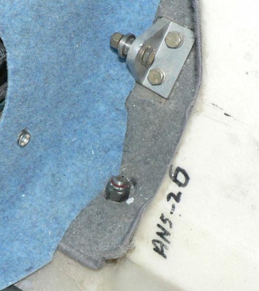
Fitted the new style sub axle which has an aluminium washer against the inner wheel bearing to the pilot side UC leg.
Washers were temporarily used as spacers for the approximate toe-in and camber adjustment until the full load of paint wings and fuel etc are added to the aircraft to see where the UC will end up.
I noted that the new stub axle is not hollow like the original axle for its full length which might have implications for its reliability. It is drilled for four AN5 bolts to connect to the UC leg instead of the original AN4 bolts.
Some pics of Warrens Sonex are included here a bit behind where he is actually up to as he is now well into doing the cockpit panels-lots of new holes to be drilled and drilled again, parts to be manufactured and riveted.
[ATTACH]5595.vB[/ATTACH][ATTACH]5596.vB[/ATTACH][ATTACH]5597.vB[/ATTACH][ATTACH]5598.vB[/ATTACH][ATTACH]5599.vB[/ATTACH][ATTACH]5600.vB[/ATTACH]
Work is stopped until after the Brobenah (Leeton) fly-in.
-
20-04-2008
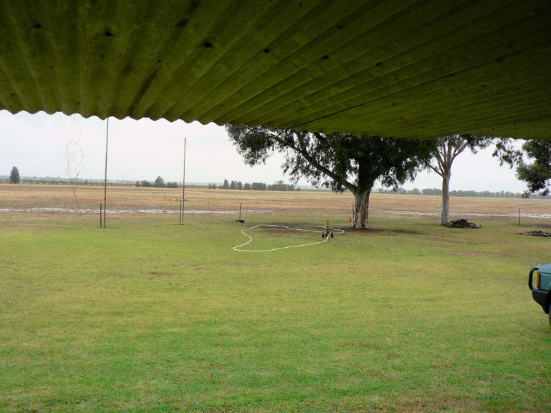
It looks like we will have about 50 arriving at Leeton (Brobenah Airstrip about a square mile area) for the Anzac weekend as well from a number of clubs around NSW.
There will also be car racing at the NE corner of the airfield.
Our first try as the Leeton Aviators Club with on site catered meals and space available for camping around the club house lawn, some room in the clubhouse for bunks and the hanger workshop.
If you are going to Temora why not drop in for a feed and a look see during the weekend.
The central strip between the club house and the AG hanger is US at the moment with the Leeton shire doing some intensive maintenance on it but will possibly be completed by the weekend. They are applying a layer of gravel to that strip with a fair bit of plant sitting on the field today. So it may not be available depending on how they consolidate the surface. Personally I would rather land on grass anyway.
But today club members have mown and marked out with white plastic drums a main grass strip roughly parallel to the the southern boundary and tarred road and there will be a grass mown cross strip which is roughly aimed at Griffith starting at the road grass strip.
Parking and tie-down of aircraft will be mostly around the outside of the club house lawn and the rear apron of the club hanger.
-
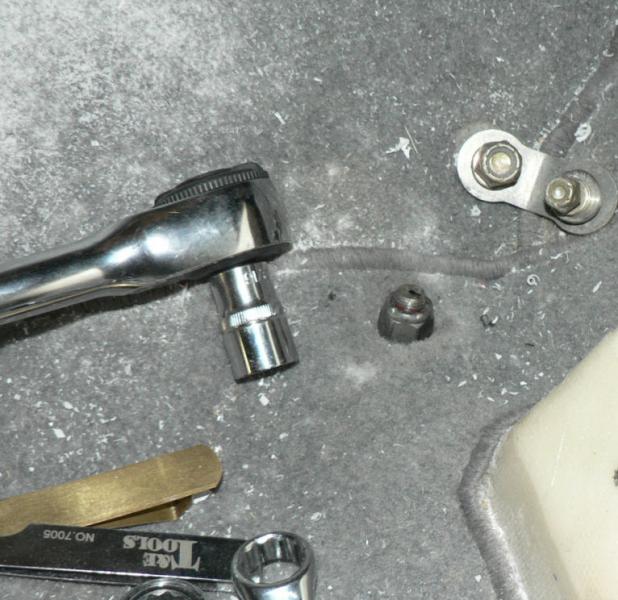
20-04-2008
Managed to do it as one person job. An upside down plastic milk crate is the secret of getting the posterior at the right height.
Then you can use one hand on top with a ratchet socket and one underneath with a good fit ring spanner as far as the centre bolt.
I also have a open end/ratchet ring spanner which is very handy but relatively expensive.
My daughter also gave me a ratchet socket holder that has a ratchet handle as well as a ratchet head.
So you can also spin the handle to do up a nut w/o moving the handle like you would do with an ordinary ring spanner.
It turns out that Dot 5 brake fluid has a Silicone content which would have to be a problem around epoxy fibreglass.
Silicone is mentioned quite specifically in my J160 Jabiru constructor's manual.
Any comments please!!!
A local suggested that I use auto transmission fluid or hydraulic fluid as used in many grain header's hydraulic systems.
-
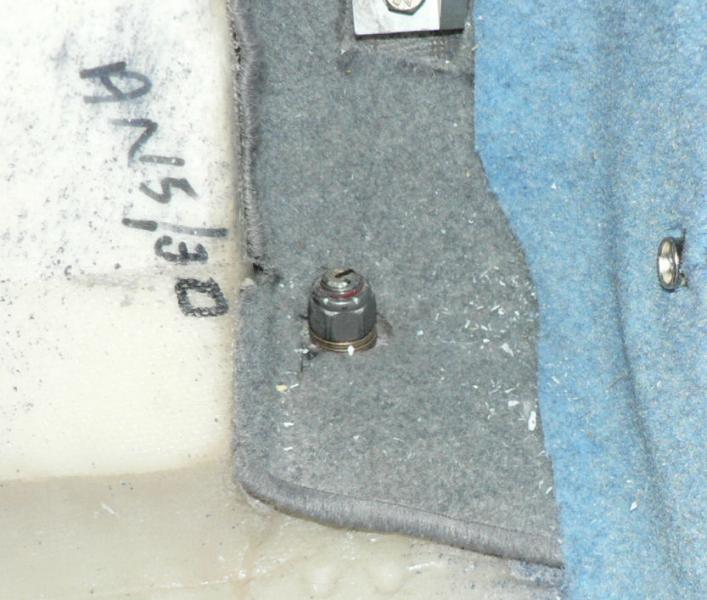
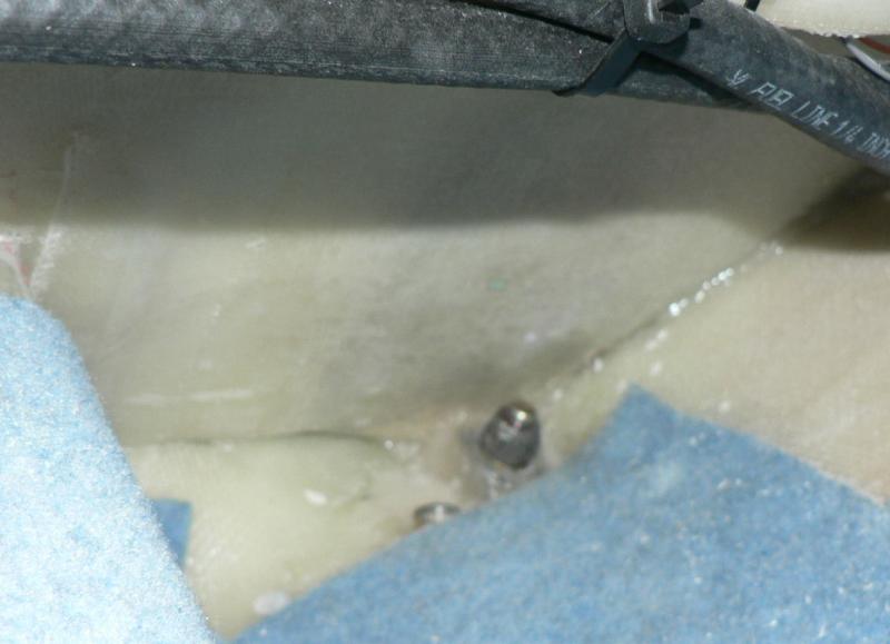
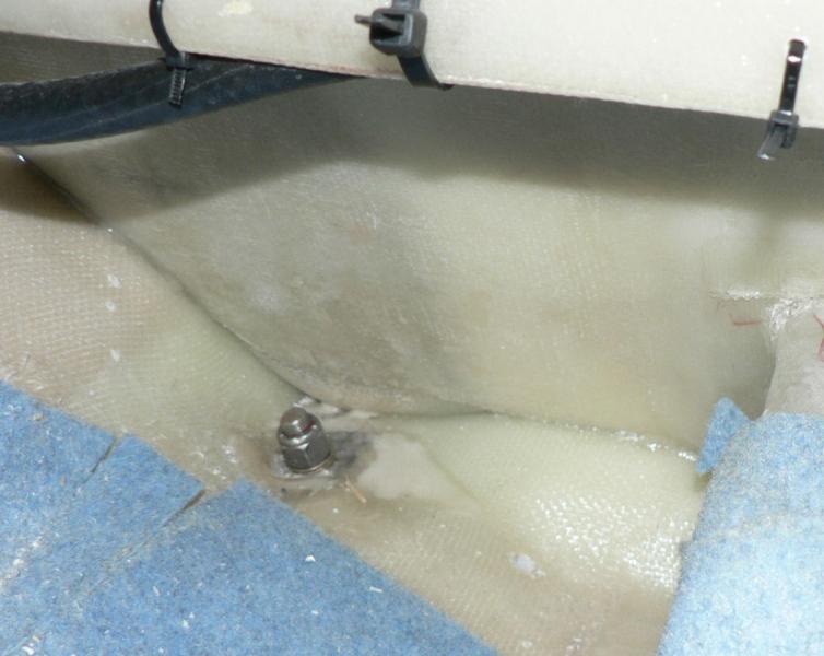
9-04-2008
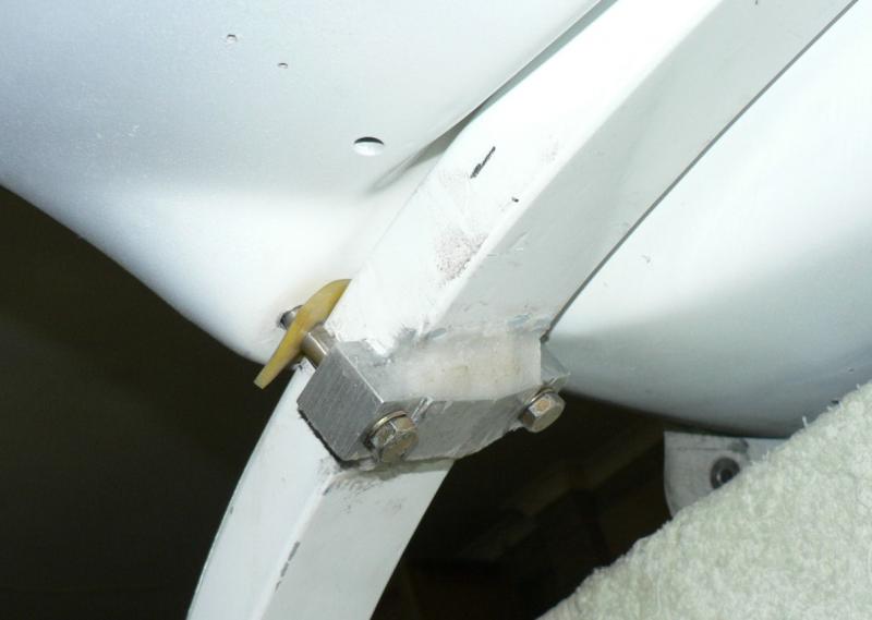
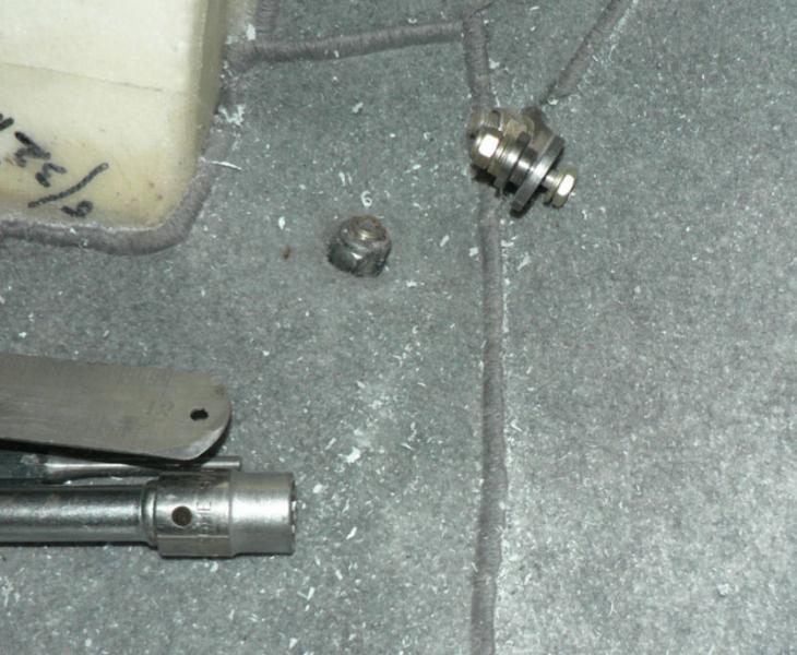
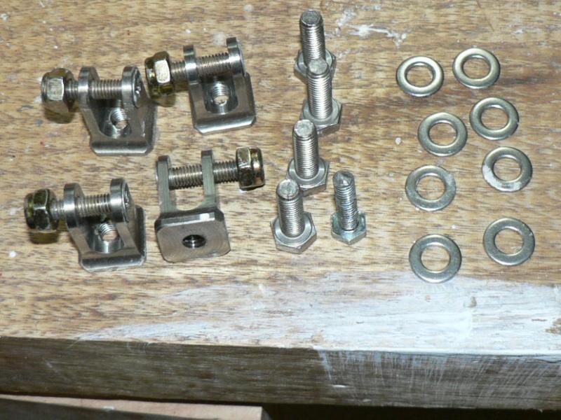
Checked all main UC bolts for adequate grip and enough correct threads protruding from the top of the nut.
Added or removed washers as required. One left behind shown up in one pic behind the passenger seat.
One of my clamp bolts needed to be substantially shorter than its companion. The original AN5 bolt sizes needed to be all different lengths so I wrote the detail onto the seats before the UC bolt change of size.
The new bolts are all probably one or two sizes longer so their details are written in the construction manual with a rough sketch showing their locations. As the manual implied the needed lengths were not as specified and even for the original diameter bolts I had order different length bolts.
Both inboard ends of the main UC legs were done up so that the rubber grommet ended up touching the floor of the cabin to prevent chattering and shock loading of the legs and bolt mounting areas.
[ATTACH]5532.vB[/ATTACH][ATTACH]5533.vB[/ATTACH][ATTACH]5534.vB[/ATTACH][ATTACH]5535.vB[/ATTACH][ATTACH]5536.vB[/ATTACH][ATTACH]5537.vB[/ATTACH][ATTACH]5538.vB[/ATTACH][ATTACH]5539.vB[/ATTACH][ATTACH]5540.vB[/ATTACH]
The recess for the UC legs were actually undercoated and top coated before the legs were mounted. This area will also be covered by a flat fibreglass sheet fairing.
Went up the street to get some "Dot 5" brake fluid. None in Leeton and ordered some and the price is $90 for 500 ml.
-
I recently did a clean up on my computer that required some software to be reloaded from the original disk which was not successful due to it's having been dropped and lightly scratched.
The normal solution was replace the program with another $160 source disk or try and repair the DVD thereby retaining the rights to upgrade the original.
So I tried using Plexus. It comes in a the pressure can pack which was developed for eliminating or reducing the scratches on aircraft windscreens and windows and is now used as well by many truck firms to maintain their windscreens. I have also been using Plexus in my J160 kit to clean up the windscreen and windows in conjunction with using a fibreglass polish.:thumb_up:
After only a squirt of Plexus and a light rub with a very soft rag to smooth up and spread the Plexus evenly and remove the excess,the DVD loaded the program without a pause.:big_grin: A number of previous attempts using the same disk before using the Plexus were unsuccessful.
-
5-04-2008
This time I used 3 parts resin + 1 part hardner for making the epoxy mix.
Removed the starboard main UC leg clamp and removed the resin from the clamp and the leg. After rubbing dry with a rag then used acetone to clean up both the clamp and the UC leg clamp area.
Re-waxed the bolts to stop adhesion of epoxy.
Applied epoxy with a brush to the clamp and the leg clamp area.
Mixed flock with the epoxy to give a fairly stiff mixture so that it would not fall off the underside of the leg..
Applied a stiff thick bead of flock to the inside of the Aluminium clamp.
Re-assembled the clamp to the UC leg and tightened up the clamp bolts.
Made sure the clamp had a fillet of flock on each side from the underside of the clamp to the UC leg.
Set up a fan heater to flow warm air onto the clamp area.
Checked the clamp leg at about 10:30 pm after going out to see that the flock was cured hard - a few more days had been wasted, but getting closer!
Ordered some AN6 matching washers from the USA.
-
My J160 kit#14 came with three fuel valves. Two of them had two inlets and one outlet for each wing tank. They both end up in a single T piece which feeds the header tank under the passenger seat.
The outlet hose from the header tank which is fitted with a low level alarm has an inline shut off valve before it reaches the electric fuel pump followed by the one inline fuel filter before going through the firewall.
-
19-J160 kit #14
Each of the wet wing tanks has a breather pipe going the full length of the wing and attached to the filler cap base so that theoretically it ends up in an air gap at the top outer end of the wing which is supposed to have a 1 degree dihedral. They should be just clear of the top outer inside ends of their respective tanks.
The inner ends exit out the top of the inner end of the tanks and are connected across the roof of the cabin with fuel hose. This connection has a T piece in it which is connected to the top of the header tank allowing any air there to return to the fuel tanks provided the small diameter hoses do not cause an air lock with the air and fuel in the line.
This could be a problem with a/c that have a header tank under the passenger seat making it more difficult to run a line from the tank to the overhead breather pipe with a continuous rise.
Ignoring the fuel vents, the connection above could also allow fuel to flow from a high wing tank to a low tank via the normal fuel supply line from the high tank then into the header tank and the header tank breather if the plane was not in balance.
It could also cross over via the supply lines to the bottom of the low tanks as all the normal supply points meet in a T piece before they enter the header tank.
There are only two brass finger screens on the bottom two connections into each wing tank so a partial or full blockage of one of these could result in fuel being drawn in down the breather tubes until they are empty if the plane is not level from the low wing tank.
If the plane were level with a partially blocked set of finger screens on one tank then if fitted with the glass sight gauges so fuel could come in from the top of one of those until it is drawn down below its intake level and then it would tend to come in from whichever bottom of tank inlet had the least blockage.
I noticed when assembling my fuel tank wing fittings that the finger fuel screens would end up partially covered by the long threaded fitting that they were screwed into. This could probably make it more likely to accumulate some permanent blockage over time of part of the finger screen unless they were removed periodically for cleaning.
I intend to pour some fuel through my tanks to try and flush any residual junk out the drain hole before they go into service. I shall have to remove the quick drain fittings to accomplish this. I have already used a vacuum cleaner to remove as much as I could from the fuel cap area and the quick drain area of the inside of each fibreglass wing tank.
All fuel that gets to my header tank has to go through a finger screen out of the header tank,
then the electric fuel pump,
then an inline fuel filter,
then the mechanical fuel pump
and lastly the carburettor.
Fuel that gets to the header tank could have got there by any of four inlets from the bottom of the tanks or from the top of either of the two sight glass fittings or possibly either of the two breather pipes in the top inner end of each tank. Only the two bottom tank lines are equipped with finger screens.
It appears to me that it would not matter particularly if one of the fuel-cap breathers were blocked in level balanced flight because the tank pressures should eventually balance once the fuel level was drawn down below the level of the top tank inlets and the inner ends of the breather pipes. This should then allow the fuel levels and tank pressures to equalise provided the finger screens are not blocked.
Fuel could flow in either direction through the finger screens.
Perhaps it would be sensible to do fuel flow tests on each tank from the bottom outlets if there were a problem with tanks out of kilter.
-
4-04-2008
The flocked clamps done yesterday had not cured during the night due to cold temps so I have set the heater up today to get them cured. Shall see what happens.
See what happened below at 23:08 hrs.
Decided the door hinge bolts holding the hinges to the fuselage were a bit light on considering that Jabiru have changed the hinges considerably since my kit #14 and I had busted a 5 mm SS cap screw when attaching one door. The dia of a 5 mm 1 mm pitch metric SS bolt is pretty small so a 6 mm bolt is a big increase in minimum cross sectional area.
my kit had 5 mm capscrews holding the hinges to the fuselage so there was just enough room to change the original 5 mm 1 mm pitch metric SS cap screws to 6 mm 1 mm pitch SS hex head bolts.
So drilled the hinges to 5 mm (the tapping drill size for 6 mm 1 mm pitch bolts ) and tapped them to 6 mm 1 mm pitch thread and bought 6 mm 1 mm pitch metric SS bolts and SS washers to match.
[ATTACH]5474.vB[/ATTACH]
Pic shows the new bolts and the freshly tapped hinges to 6 mm 1 mm pitch SS.
The pic shows the replacement 6 mm bolts & washers as well as a 5 mm 1 mm pitch SS Hex bolt in the pic although the supplied bolts were capscrews 5 mm 1 mm pitch cap screws not shown in the pic.
23:08 hrs :ah_oh: Just figured out why the second leg clamp did not cure - instead of adding 3 parts resin plus 1 part hardner I had added one more part resin instead of hardner.
So have turned off the heater and tomorrow I will remove the leg and clamp, clean off the mixed resin and flock and clean it with acetone.
Then will mix up some resin plus hardner apply it to the clamp and leg then mix the epoxy with flock apply it to the clamp and reinstall it.
-
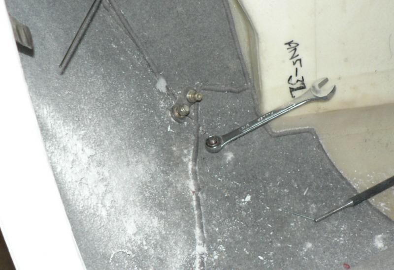
3-04-2008
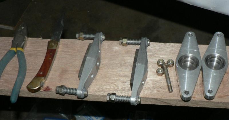
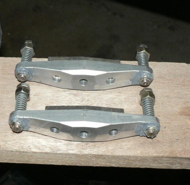
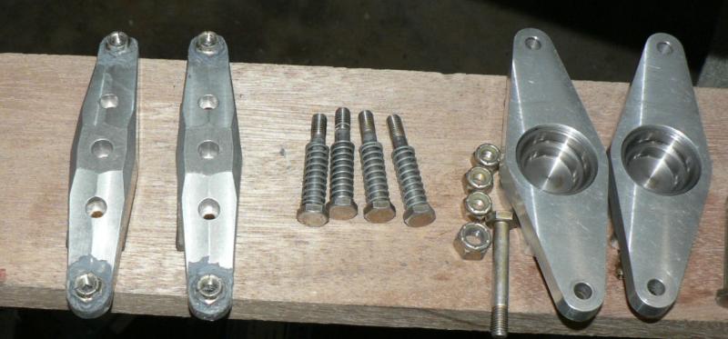
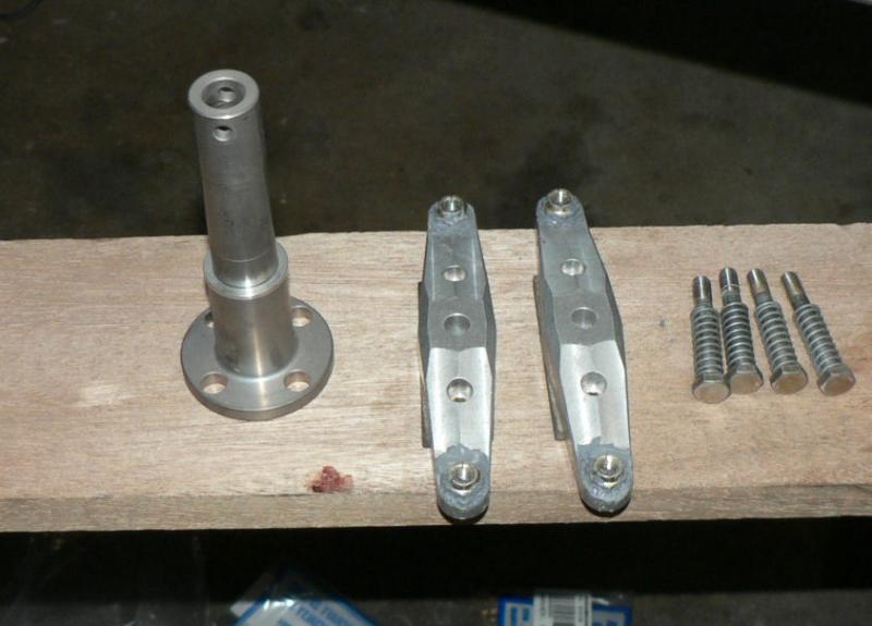
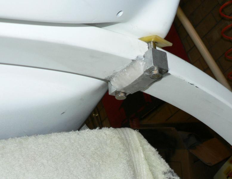
Completed the flocking of the starboard main UC clamp to the UC leg with similar procedure to that used on the port UC leg clamp done yesterday.
[ATTACH]5466.vB[/ATTACH][ATTACH]5467.vB[/ATTACH][ATTACH]5468.vB[/ATTACH][ATTACH]5469.vB[/ATTACH][ATTACH]5470.vB[/ATTACH] [ATTACH]5471.vB[/ATTACH][ATTACH]5472.vB[/ATTACH][ATTACH]5473.vB[/ATTACH]
The last pic shows that the port main UC leg inboard bolt needs to be tightened up. It may need a few washers to pack it up or a shorter bolt.
As well as that the starboard inboard bolt might be a bit too tight.
The finish of the port side clamp flock was not as neat as the starboard clamp flock done today due to the interruptions during the job yesterday. It can probably be made more presentable with some selective filing and sanding.
-
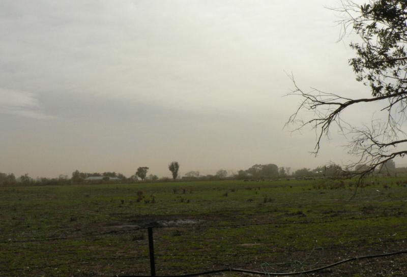
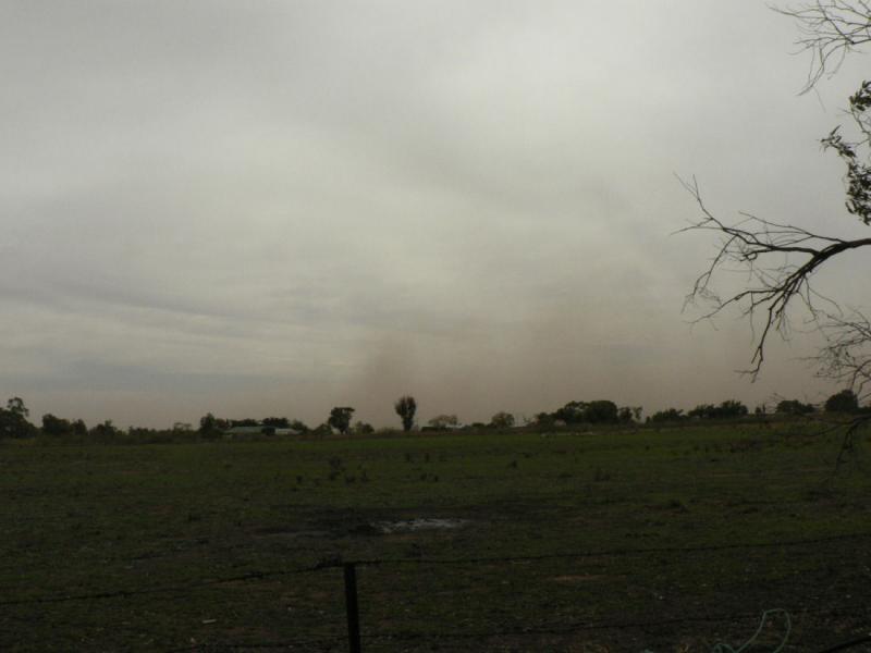
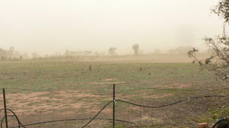
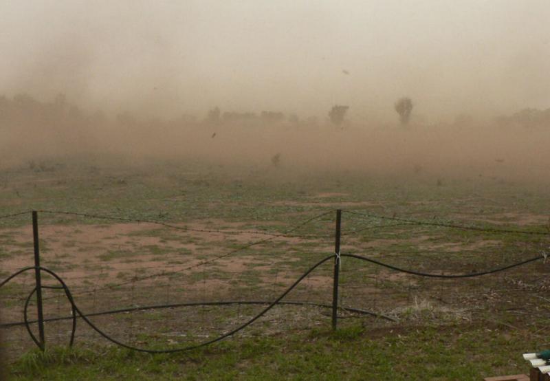
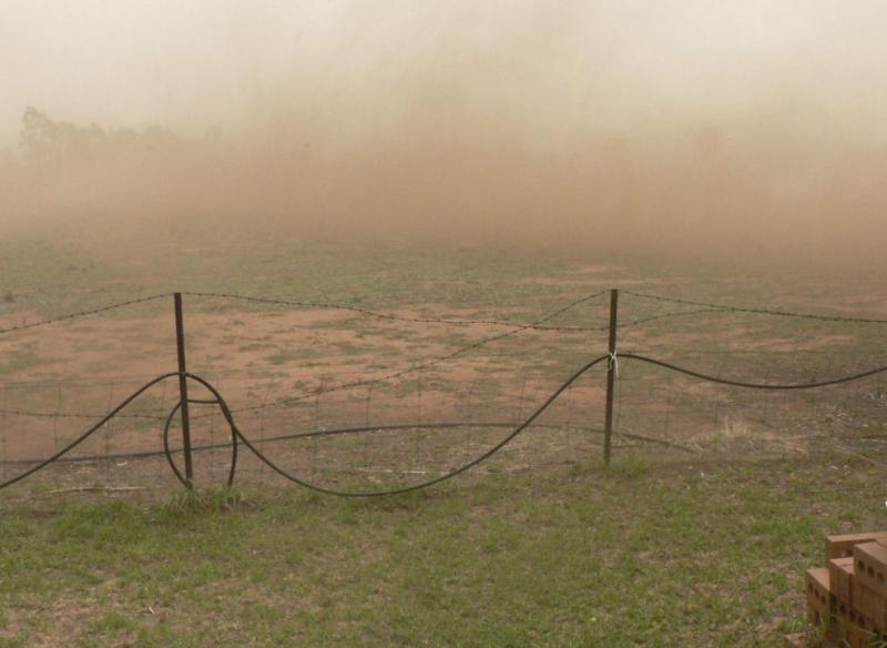
2-04-2008
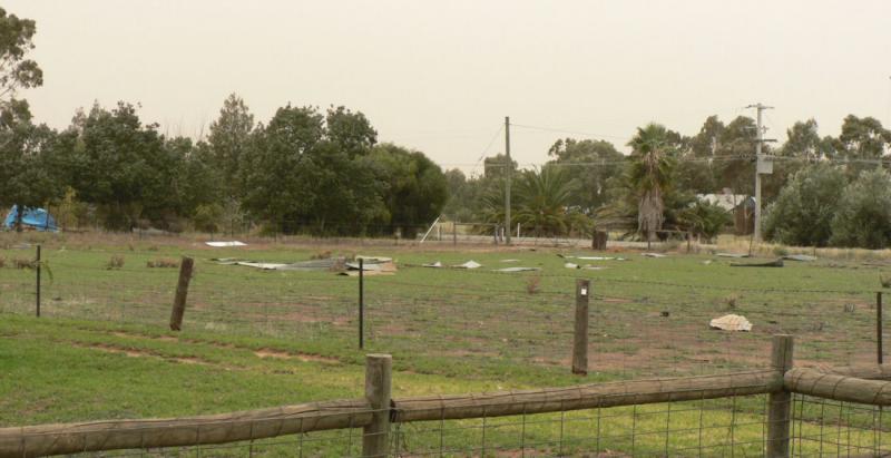
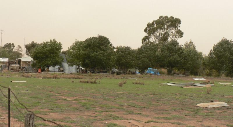
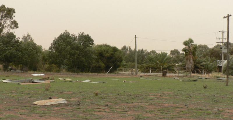
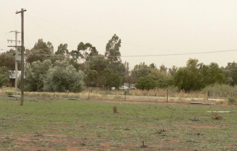
Today started to flock the UC clamps to the UC legs. I had just got started when there was a lot of wind noise outside. So opened the shed door to see an approaching dust storm (see rain photos from the same door a few days ago).
[ATTACH]5450.vB[/ATTACH][ATTACH]5451.vB[/ATTACH][ATTACH]5452.vB[/ATTACH][ATTACH]5453.vB[/ATTACH][ATTACH]5454.vB[/ATTACH]
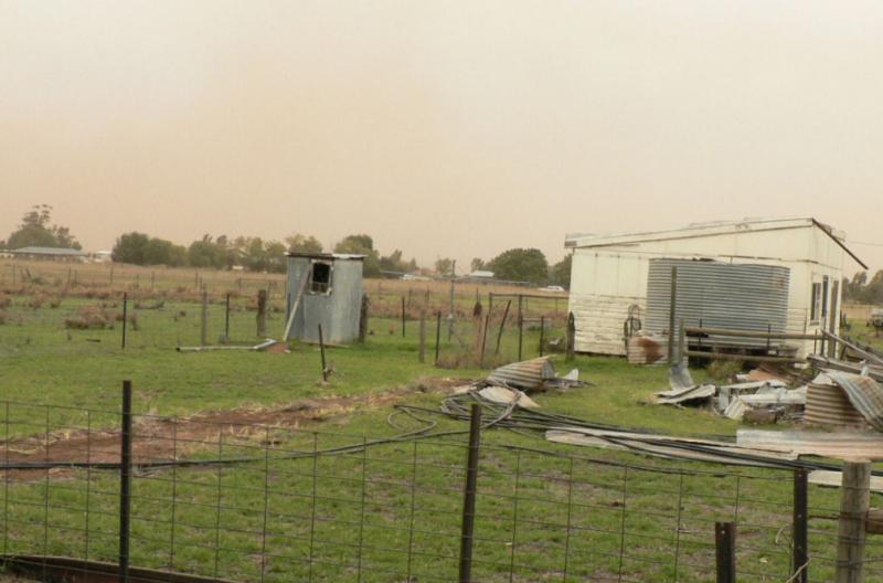
It was fairly noisy but I heard the phone ring it was the next door neighbour telling me the roof had blown off our old unoccupied cottage about 50 metres from our house but it still had some gear in it that was to be removed on Friday. The shed on the ground was the result of a previous wind storm just after we first moved in many years ago.
[ATTACH]5455.vB[/ATTACH][ATTACH]5456.vB[/ATTACH][ATTACH]5457.vB[/ATTACH][ATTACH]5458.vB[/ATTACH][ATTACH]5459.vB[/ATTACH][ATTACH]5460.vB[/ATTACH][ATTACH]5461.vB[/ATTACH]
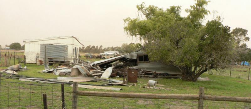
The roof had flown off and landed on the old still live power line breaking it then dispersed itself around the paddock. One wire of the live power line was hanging low across the public road. I also had a makeshift pool heater with poly pipe laying on old gal sheets. It had also been picked up and spread around.
[ATTACH]5462.vB[/ATTACH][ATTACH]5463.vB[/ATTACH]
Not long after the roof came off the wind and dust returned and continued for some hours with a smattering of rain that did not seem to clear the dust but put a lot of mud on the vehicles.
Work had been going on the UC during the above interruptions followed by a few long reds.
Removed the LHS UC leg and marked it on the underside for the clamp location. Removed the paint with rotary emery cloth and cleaned the aluminium clamp. Then the fibreglass leg and the aluminium clamp were cleaned up with acetone and then a layer of epoxy brushed on both.
A heavy bead of flock was applied to the clamp and it was reassembled on the AC with the port main UC leg.
[ATTACH]5464.vB[/ATTACH][ATTACH]5465.vB[/ATTACH]
-
1-04-2008
Just mucked it up again. Did the whole post and quit without saving it
.Fire-ban ended yesterday so was able to get rid of some large cardboard boxes today from the garage to give a bit more room to move. Due to forecast strong winds for tomorrow there is a total fire ban tomorrow.
Lifted the front of the AC onto a piece of timber to lower the tail so that it would clear the ceiling.
Used a saw horse with a piece of wide soft wood screwed to it to raise its height a few inches to support the cabin just in front of the main UC just to the rear of the strut lugs just below the cabin doors. The balance point turned out to be still forward of this location with the engine fitted and elevator not fitted so the main UC could be safely removed without fear of the tail falling on the ground.
The main UC wheels are just clearing the floor which is not really apparent in the photos.
[ATTACH]5445.vB[/ATTACH][ATTACH]5446.vB[/ATTACH]
So the main UC gear can be removed and prepared for epoxying the aluminium clamp to the fibreglass legs.
-
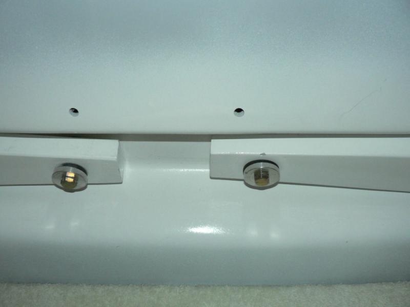
29-03-2008
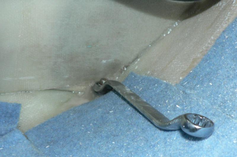
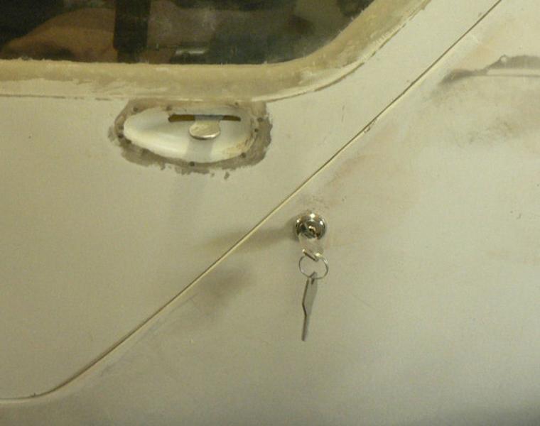
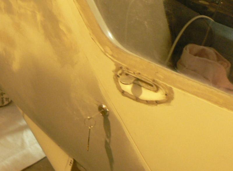
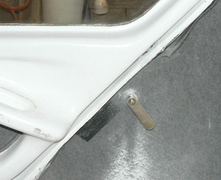
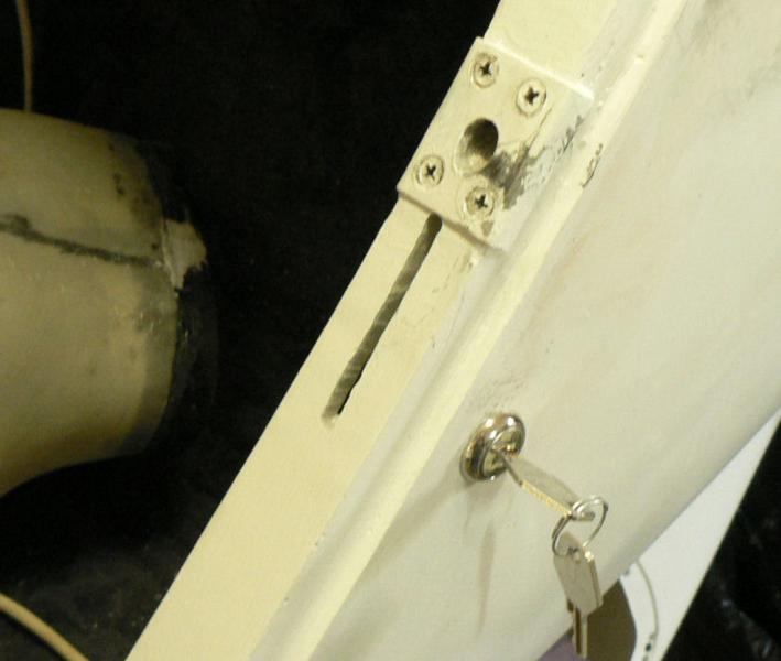
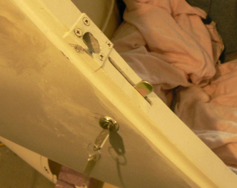
Installed door locks on RHS & LHS of fuselage.
The position of the locks was marked in pencil close to the door catch bolt allowing for the rotation of the lock in the slot.
The elongated hole was drilled and filed out to fit the lock barrel cage so that the tab would be at right angles to the frame when in the locked position.
The distance of the arm was measured and a slot cut in the door frame to match and trimmed up to clear the arm when in the locked position.
A corresponding slot was marked on the door itself and cut out with the slotting tool on the Dremel with the door flush with the fuselage.
[ATTACH]5384.vB[/ATTACH][ATTACH]5385.vB[/ATTACH][ATTACH]5386.vB[/ATTACH][ATTACH]5387.vB[/ATTACH][ATTACH]5388.vB[/ATTACH][ATTACH]5389.vB[/ATTACH]


 .
.

J160 Kit#14 various with Photos
in Jabiru
Posted
27-05-2008
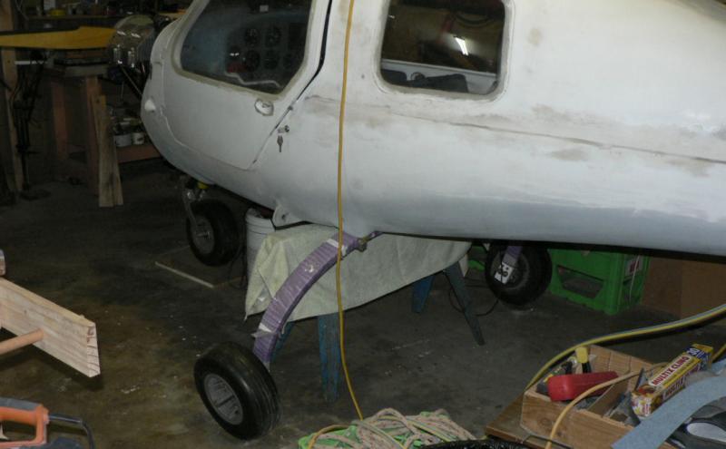
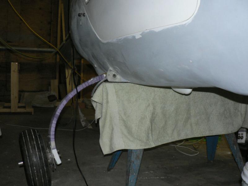
Put up another short shelf in the corner behind the engine above the air compressor in its box.
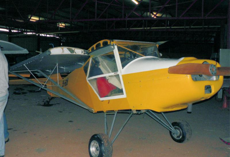
Cleared the main floor space at last so that the engine hoist could be manoeuvred over the cabin again. Note the front wheel is packed up a few cms so that the vertical stabiliser just clears the ceiling of the carport.
Both main UC wheels are just clear of the floor.
[ATTACH]5767.vB[/ATTACH][ATTACH]5768.vB[/ATTACH][ATTACH]5769.vB[/ATTACH]
Tomorrow should be able to line inside the starboard tyre with foam rubber, change the axle and drill fibreglass leg for and fit larger bolts to axel and UC.
I will wear my mask when I drill the leg this time!:confused: