

Ross
-
Posts
729 -
Joined
-
Last visited
Content Type
Profiles
Forums
Gallery
Downloads
Blogs
Events
Store
Aircraft
Resources
Tutorials
Articles
Classifieds
Movies
Books
Community Map
Quizzes
Posts posted by Ross
-
-
Hi J430
I'm with you.
Unless the person measuring it was a surveyor you would have to assume that they measured the slope strip distance not usually recognising that the distance measured along a level surface would be shorter than one measured along a uniformly sloping surface.
This makes the sine function the sensible one to use in calculating the angle.
Alternatively the first example slope could be described as say 2 on say almost 68 for the first example where 68 represented the horizontal not quite the level distance and which is not true in this case.
In reality it would be 2 on slightly less than 68 as the level distance is slightly shorter than the hypotenuse even allowing for the curvature of the earth which would tend to increase it.
But we cannot measure this easily so use the 2/68 and the sine-1 function.
-
Congratulations on your first post Don. Not quite like the feeling of your first solo in an aeroplane especially if it is your own homebuilt.
You might tell us some information on that plane by putting it in the Gazelle thread in the Hanger forum or start a new thread in the Hanger forum called something like "Flying a Kitfox" or whatever you fancy.
Having done 600 odd hours in it you must have some good maintenance or experience that you could pass on to other owners or pilots of Kitfoxes.
-
08-07-2008
The single 6' length of SS hinge pin arrived today taped to a piece of timber in a box long enough and with a cross section possibly large enough to house a Jabiru wooden propeller.
So mounted the cowls, ran my makeshift D drill made from hinge pin material through each pair of the combined hinges a couple of times and then inserted the hinge pins.
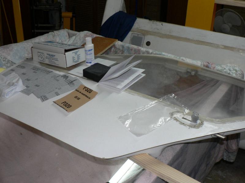
Sat the pilot door in place w/o mounting the hinges and had a go at masking up one window.
After discovering that I had not stripped off the backing strip from some double sided tape and was trying to stick some more tape to the backing strip which seemed remarkably uncooperative, I started again.
For the second attempt I used some narrower double sided foam tape on top of the wide tape (after removing it's shiny backing strip this time).
The narrower tape is easier to form around a curve rather than trying to cut a curve on a wide tape w/o damaging the window. You also get to have multiple attempts at the curve w/o having to cut a new piece of tape.
I think I might have to go a third time and only use the narrow double sided tape without the wide very thin stuff underneath which could have had the paper applied to it rather than another layer of tape. I will probably go and have a talk to my panel beater before I go much further.
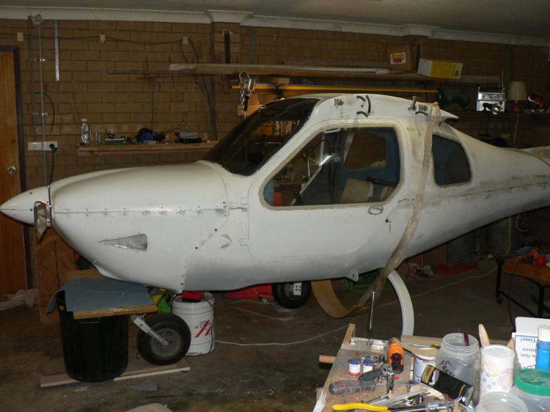
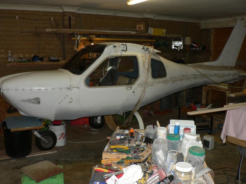
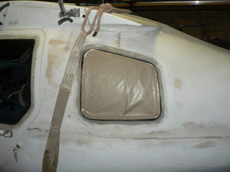
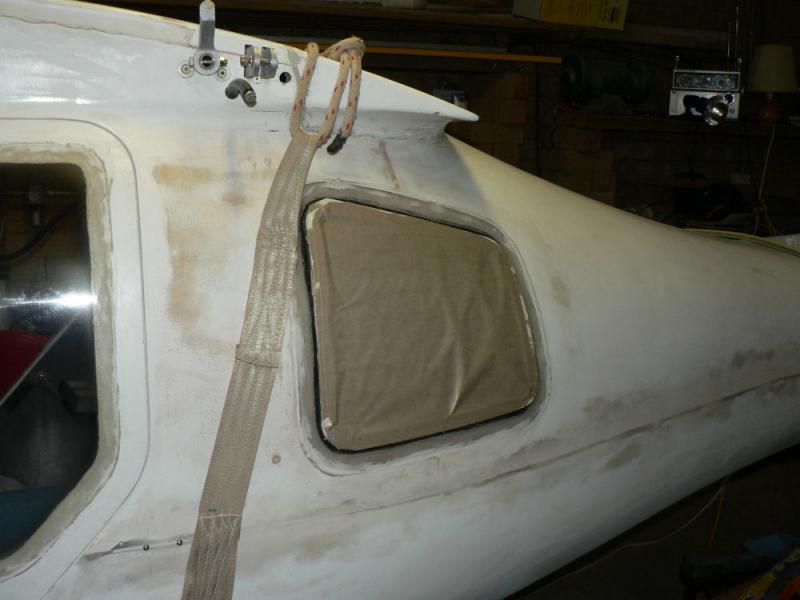
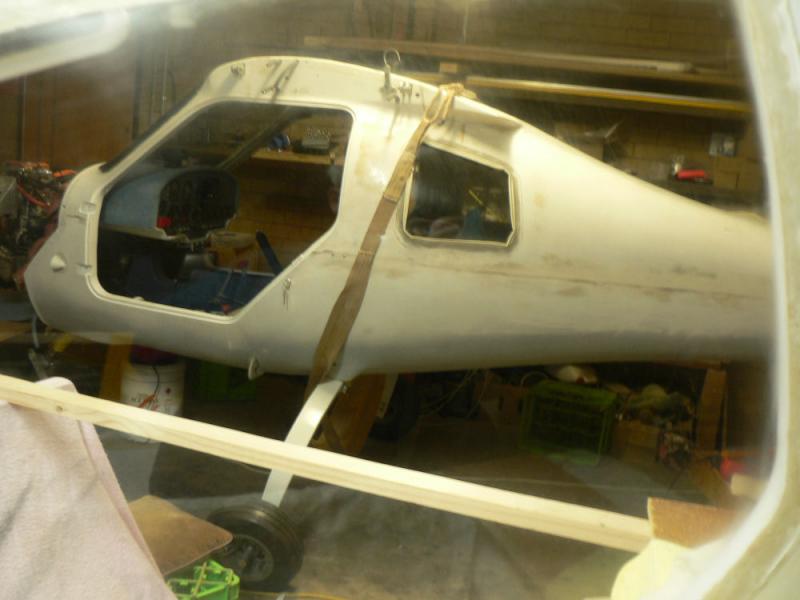
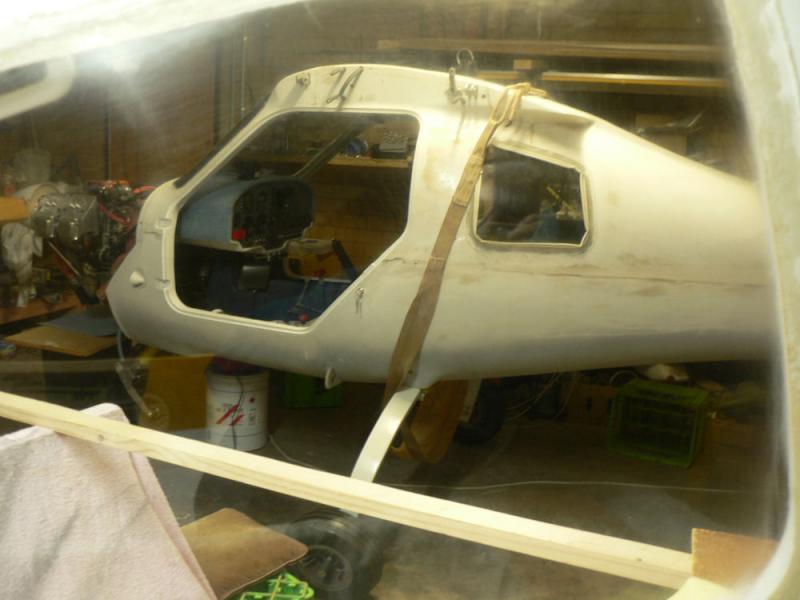
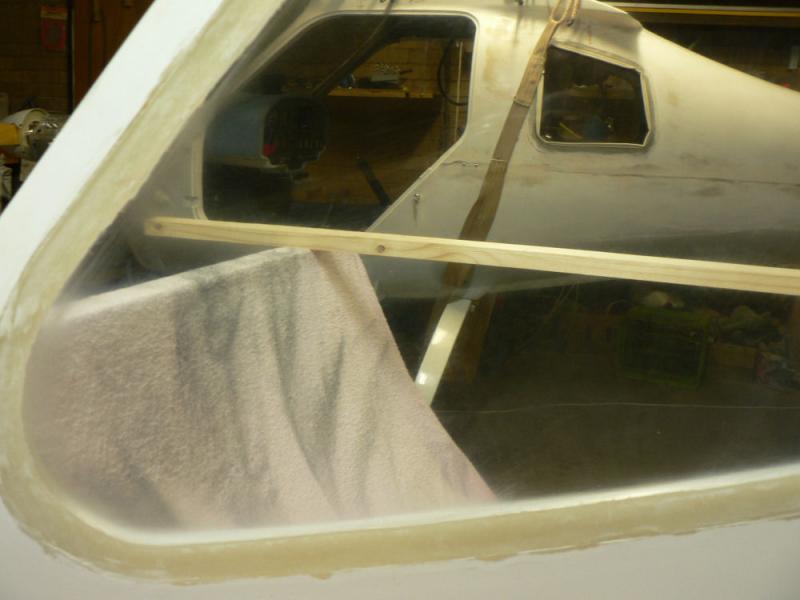
[ATTACH]5962.vB[/ATTACH][ATTACH]5963.vB[/ATTACH][ATTACH]5964.vB[/ATTACH][ATTACH]5965.vB[/ATTACH]
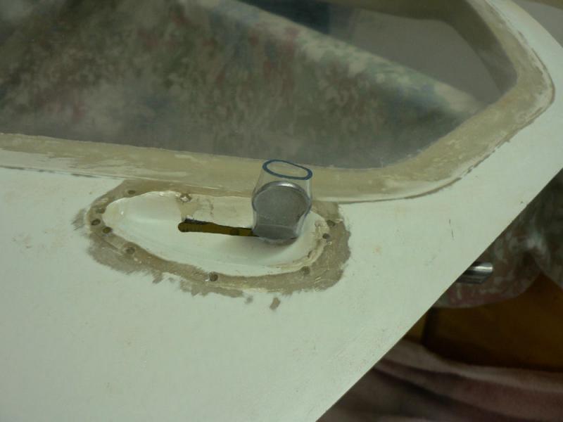
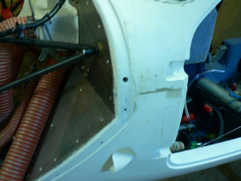
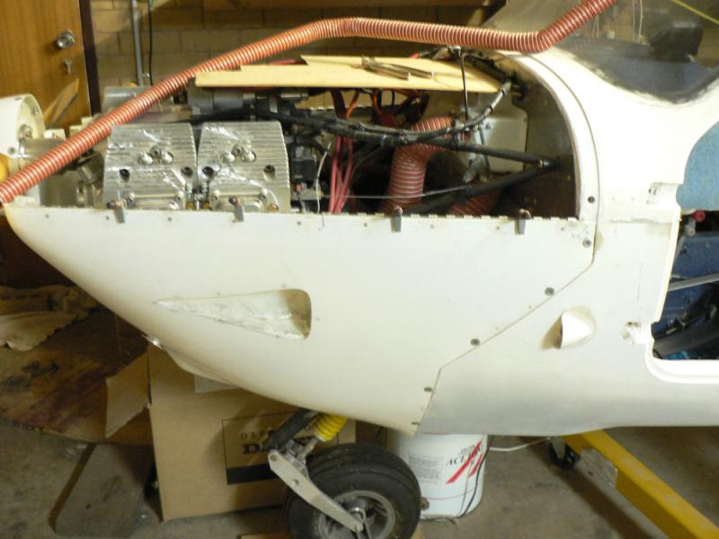
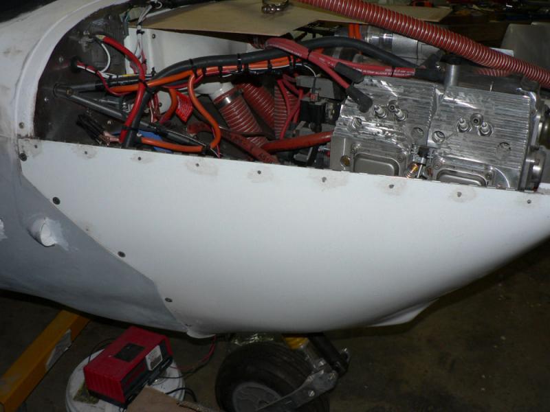
Pics are just a general shot of the a/c from the pilot side with one door sitting in place but not attached and the cowls in place with hinge pins inserted and most of the bottom cowl screws installed with Tinnerman washers in place.
The window pic shows the narrow tape on top of the wide tape with brown paper on top of the narrow tape.

-
Hi Phil
I just copied your post into the buffer by dragging the cursor over it then closed the forum.
You can then go to most programs that have provision for insrting the buffer contents into a file or a post.
Logged back into the forum and pasted the contents of the buffer into this post as below.
A variation on that might be to save it periodically into say a Word file then when you have it right paste the contents into the post you are working on particularly if it is a long convoluted story where it is difficult to see if your post makes sense until you can see the whole thing.
Your Text below was inserted by pasting from the buffer in my earlier session on the forum.
A common way I used to loose posts was caused by by accidently opening two copies of the forum by double clicking.
The first one would log in useing my user name then the second one would probably start up with my user name again and normally with both running the forum the second one should normally not have the right to write data to an area that is already being worked on by the first open forum. This depends on how it is set up by the programmer i.e. with less rights to write.
It is not very logical to have two posts writing from different sessions of the forum using the same username.
It is difficult enough following the argument when half a dozen people are contributing to the thread all at the same time especially when a post of twenty or thirty lines of information like this one suddenly appears on your screen while you are inserting text.
If I woke up that I had done that after starting work on a new post I could just highlight the post I was trying to create thus putting it in the buffer then shut down that session and insert the contents of the buffer into a post on the forum session that was started first. Easy to get confused at this stage. I have not checked out exactly what happens in this situation lately.
Even better not to shut down the second copy until you make sure you have copied all that you want across to the first opened forum if the system will let you do that.
I have done that a few times - particularly as I am a very slow typist or rather not a typist at all!
Regards
Ross
Just makes me mad when you lose your post into cyber-space somewhere. Here goes again.
Thanks for the queries, IAS 110-112 I would agree with J430 on the TAS at 3-4000" It was apity that I never caught upwith Don C, we could have had a good chat re the oil temps. Since installing the cowl mod (to the oil cooler) the temps have improved greatly, on the trip in the higher OS temps I never got passed 100 in climb, and around 90 in cruise. I kept W100 oil in for the trip.
Changing subject. Any help would be appreciated for Caloundra. I have friends there and would like to visit when the weather fines up. Looks straight forward enough but local knowledge is always good.
Cheers,
Phil.
-
28-06-2008
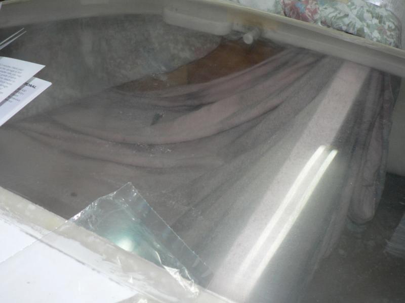
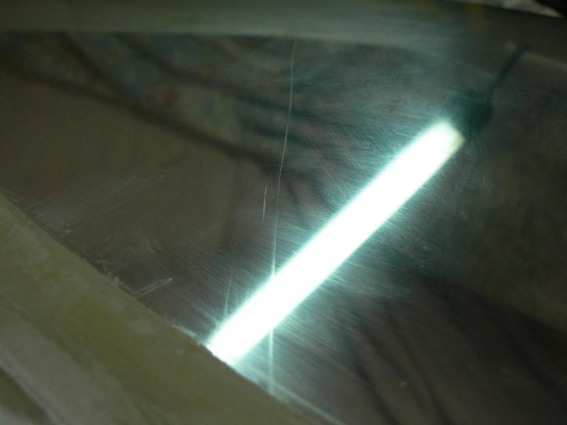
Did the other side of the door window with the http://www.micro-surface.com KR-70 kit up to using the Micro Gloss polish.
Still a bit rough so repeated the last three passes with the Micro mesh abrasive sheets then the fine cut with the Micro Gloss.
Finished off by using Plexus on both sides of the door window.
[ATTACH]5944.vB[/ATTACH][ATTACH]5945.vB[/ATTACH][ATTACH]5946.vB[/ATTACH]
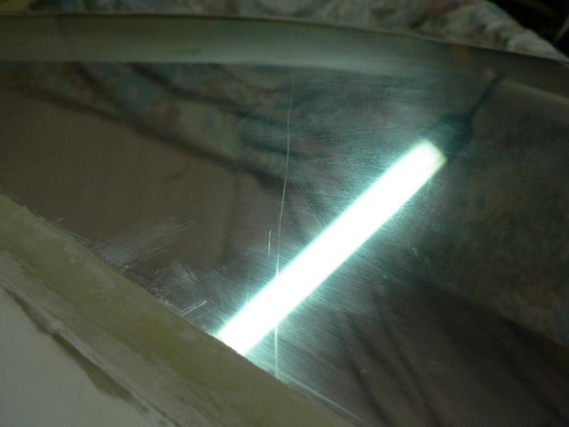
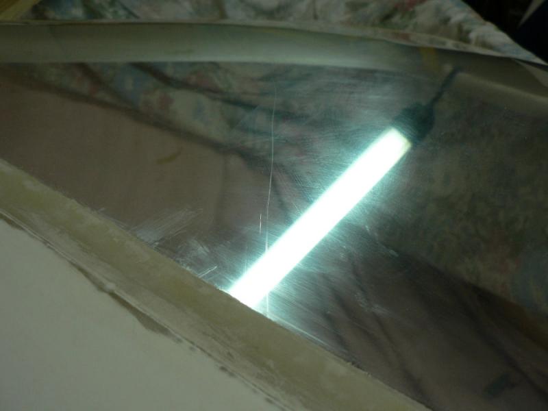
Photos were taken through the door window of the plane with overhead neon lights as the only lighting.
Still some cloudiness showing up around the edges.
-
My new ASIC card shows Jun 10 on the face. I assume it is the same as the old one.
I sent off my application for a new ASIC card on 23rd May 2008 with authority to charge $160 against my Mastercard.
My MCard account was debited by $110 by RAAust on 30th May.
RAAust sent a letter dated 13th June to say it had been processed and was ready to be sent out once I posted in my old card.
I posted the old card the day the notification arrived.
The new card arrived about 26th June 2008 - just over 5 weeks.
-
27-06-2008
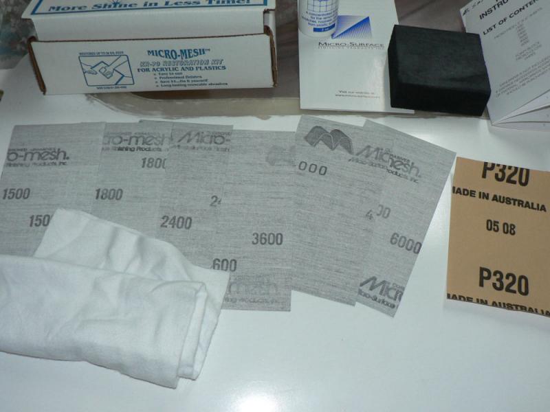
Thanks to Brentc for the info on the info on Micro Mesh from Micro Surface for repairing scratches etc.
The kit I bought was the most basic one at www.micro-surface.com and it arrived today.
The following is a list of the kit contents:-
It comes with a black rubbing block to wrap the wet and dry around and hold by hand.
Two pieces of fine linen for cleaning and polishing
Six pieces of wet and dry from 1500, 1800,2400,3600,4000 to 6000 grit.
These are mounted on a flexible rubberised backing and will withstand repeated use and washing.
[ATTACH]5941.vB[/ATTACH][ATTACH]5942.vB[/ATTACH][ATTACH]5943.vB[/ATTACH]
An instruction leaflet explaining each step of the process of eliminating scratches or other wear and tear.
A bottle of Micro Gloss for the final polish using the supplied cloths.
The 320 Grit sheet shown in the first pic is not supplied. They tell you to use 400 grit. I have a roll of 320 grit wet and dry.
The 400 grit sheet is used to completely eliminate scratches by rubbing across them until they are cut out.
Thus we ended up with a milky white opaque surface on my Jabiru window.
So the six sheets are successively used from coarse to the finest wet or dry to convert the opaque surface to a clear surface.
This is done by using successive sheets from the kit by rubbing out the the scratches from using the previous sheet. This will entail frequent cleaning of the abraded material.
I did it dry using an air compressor air gun to blow it out of each sheet and off the door window.
Each successive pass is done at right angles to the previous one a benefit of which is being able to decide if the marks from the previous sheet are gone.
Once all the sheets have been used the surface is cleaned with water and the supplied cloth which is then washed and used to wipe off the surface again.
Rinse the cloth again, wring out, wrap it around the rubbing block.
Apply a dime sized dollop of Micro Gloss from the plastic bottle and apply to about a square foot area (30 cm x 30 cm) using long straight strokes. You may need to add a bit more water to prolong the polishing. Keep going till it is virtually dry.
Once it dries it can be polished/removed with the other clean dry cloth.
The process is explained in more detail in the small supplied instruction leaflet.
So far I have only done one side of this door window and it definitely has dust on the other side and probably more scratches that may need repairing.
So the pics show that the deep scratches across the windows have gone but I really won't know if it is a reasonable job till I turn it over and have a go at the other side.
There are a number of other products advertised for this job and I am in no position to recommend any particular one over the other.
-
26-06-2008
4xAN4-21A bolts arrived today plus heat proof lock nuts (no plastic) plus 6xMetal lock nuts to suit AN3 bolts. AUD$69.
Replaced the top two AN4-20A engine mount to firewall bolts with NYLoc style nuts with AN4-21A bolts with metal heat proof nuts.
Checked out the engine thrust line. Plus 0.1 degree.
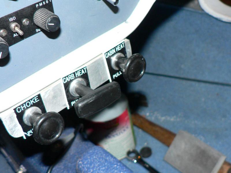
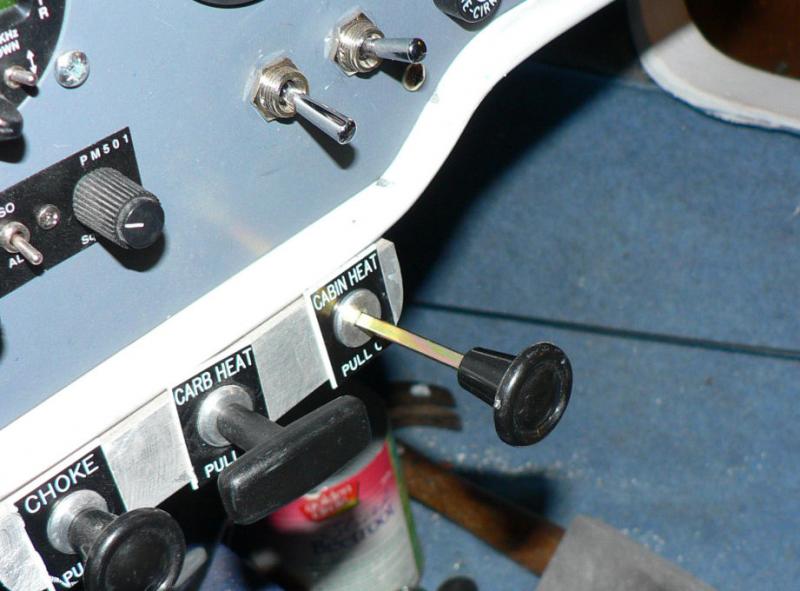
Resoldered the choke control wire connection.
Checked out and adjusted the choke cable stroke.
Adjusted the throttle stops in the cabin to allow the idle screw stop at the carby to work.
Resoldered the cabin heat cable connection.
Make sure cabin heat valve is seating in shut mode.
Resoldered the carby heat cable connection.
Make sure the carby heat valve seats in on and off positions.
-
23-06-2008
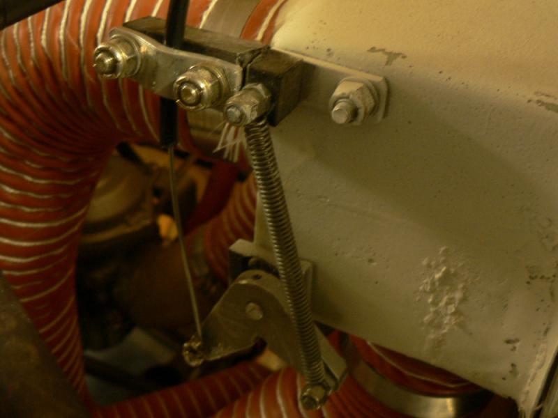
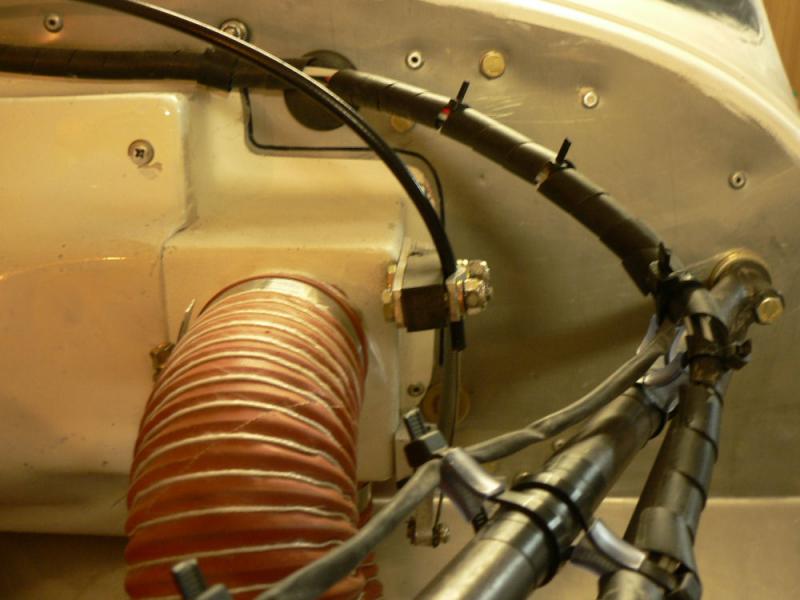
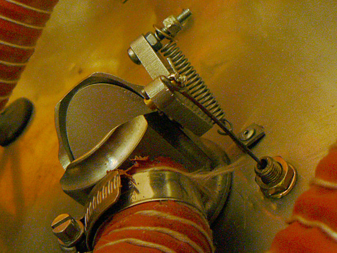
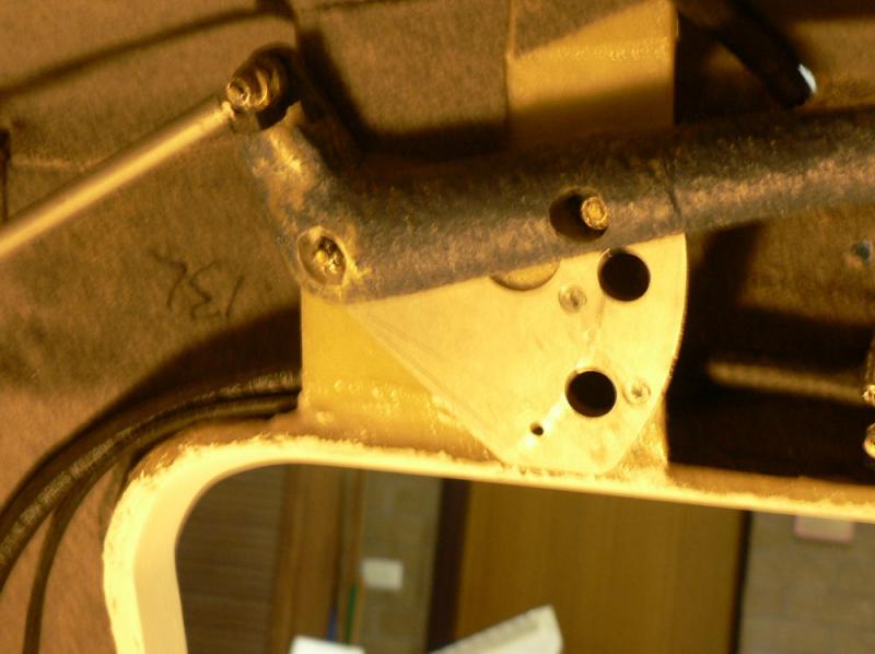
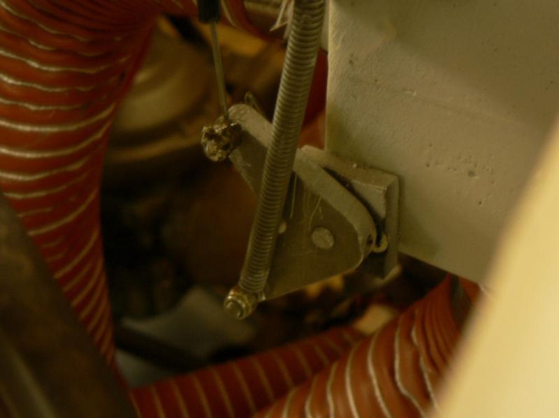
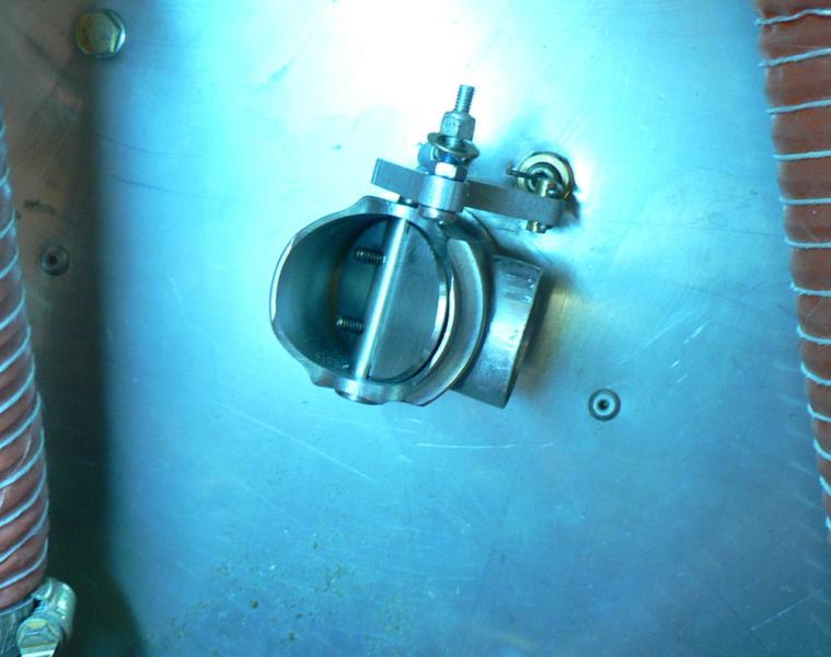
Modified the carby heat control cable anchor and mounting to get a better angle on the cable and less friction. Also eliminated the outer cable from rubbing on the inside of the top cowl.
Started off by loosening the clamp desoldering the inner cable anchor pin and withdrawing it from the hollow anchor pin.
The cable was shortened by inserting it through the clamp until it operated most freely and cleared the top cowl.
Then the outer cable cover was marked before withdrawal from the clamp. The inner cable was retracted in the cabin and the outer cable cut on the mark with a cutting wheel mounted in the angle grinder before reassembling and soldering the cable into the pin.
The fibre block was cut so that the outer end under the clamp could be twisted slightly to improve the cable friction.
Care was taken to ensure the clamp was not applying friction to the inner cable.
The clack noise of the butterfly valve was a good sign that the valve was operating fully in both directions when operated from inside the cabin.
[ATTACH]5925.vB[/ATTACH][ATTACH]5926.vB[/ATTACH][ATTACH]5927.vB[/ATTACH][ATTACH]5928.vB[/ATTACH][ATTACH]5929.vB[/ATTACH][ATTACH]5930.vB[/ATTACH][ATTACH]5931.vB[/ATTACH]
The photos show that a better soldering job needs to be done on it and the cabin heater control cable.
A long bolt added to the flap quadrant as a limit stop was removed as being possibly dangerous in the cabin. The location was the lower empty 3/16" dia. hole in the quadrant above the pilot's seat.
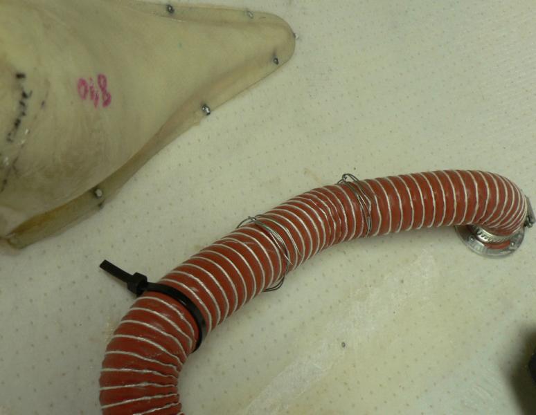
Two of the plastic ties on the cold air intake for the cabin heater were replaced with SS tie wire. This should prevent possible failure of the replaced plastic ties due to heat from their proximity to the exhaust stack.
-
Brent thanks for that information and your kind offer. I did not know about MicroMesh so have added some to my current order list. I have quite a few areas that could do with a good going over.
The current orders were stuffed up so I have been waiting for an order that was not placed - not Jabiru. I think it is all in hand now.
-
17-06-2008
I discovered a week or two ago that one of the door windows had a scratch right across it from the handle of the other door. So both door handles now have a piece of plastic tube over them to prevent this recurring.
I had another look today and the scratch has not gone away; it is still there in fact there were two of them. They must be multiplying.
So I have done about an hour of rubbing across the scratches with fibreglass colour polish using a soft rag and moving to a clean part of the rag as soon as the working part was clogged up which did not take long.
To check it out, cleaned most of the polish off and then applied some Plexus cleaner & polish to the scratched area. It was then rubbed in and polished off before having a good look with a neon light under the door to make the area more visible.
There is still a fair bit of dust on the bottom side of the plastic which is also standing out in the photo. The scratches are standing out much more in the photos than when viewed by eye only including other existing scratches which was not obvious in the camera viewfinder.
It is obvious from the photos that the exercise will need to be repeated maybe a couple of times although when viewed by eye only I was tempted to leave it alone.
[ATTACH]5914.vB[/ATTACH][ATTACH]5915.vB[/ATTACH][ATTACH]5916.vB[/ATTACH][ATTACH]5917.vB[/ATTACH]
There is a big improvement from the initial untreated scratches which were not photographed.
-
12-06-2008
Removed the bottom cowl and proceeded to remove the previously stuck on strip and spare lugs by heating them with the hot air gun then prising them off with a small chisel.
Added another aluminium lug in a more suitable place for the cabin cold air inlet scat hose and used quick set araldite to attach it to the cowl.
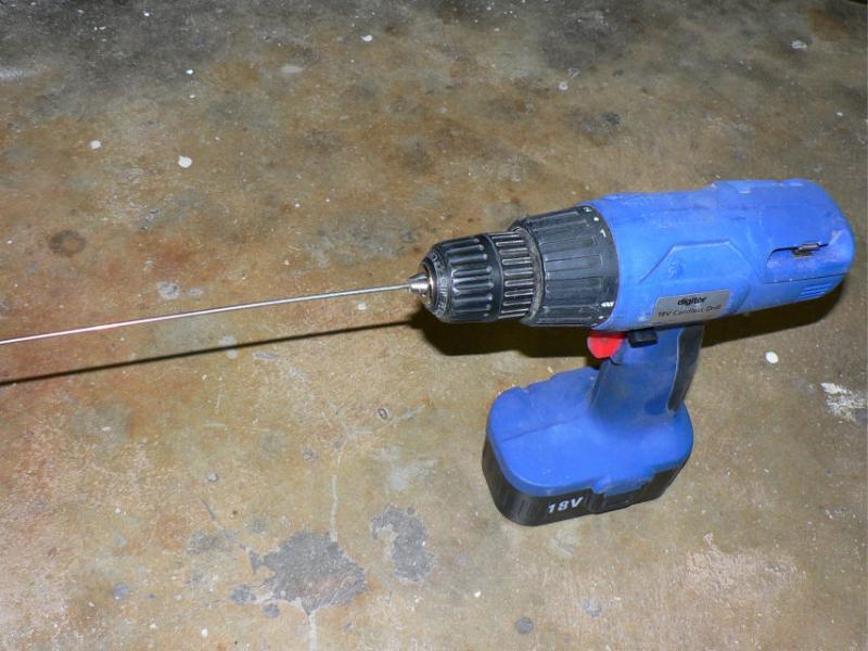
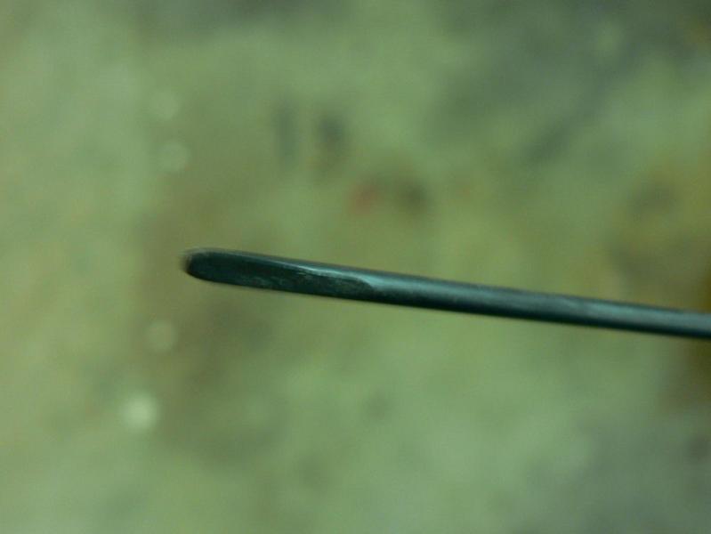
Used a length of SS 2.3 mm diameter SS hinge pin to clean out piano hinges on cowls.
The wire was mounted in the chuck of an electric drill, the far end of the wire was flattened on one side to about half the diameter of the wire by removing metal from that side using a bench grinder.
The idea is to end up with a D shape on the end of the drill.
The end was also bent slightly outwards with a pair of pliars to give it more bite when inserted as a drill through the long hinges.
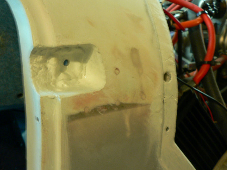
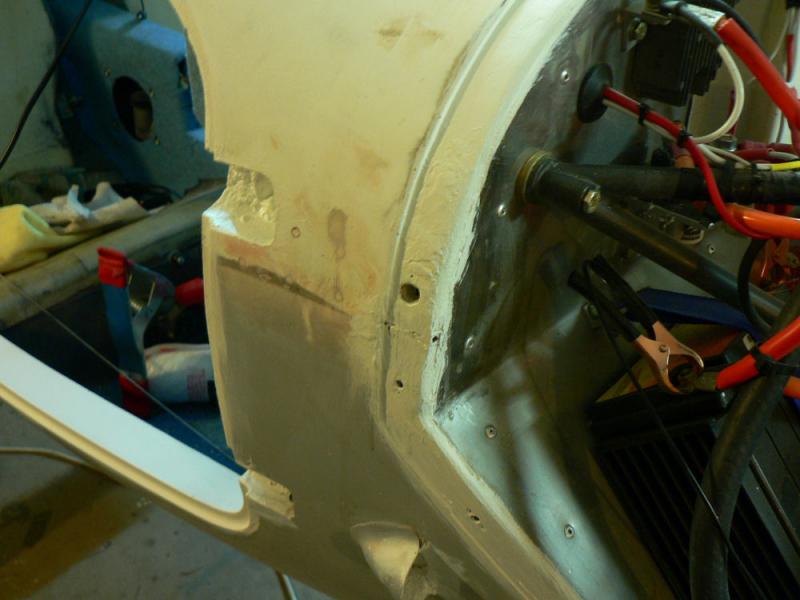
[ATTACH]5878.vB[/ATTACH][ATTACH]5879.vB[/ATTACH][ATTACH]5880.vB[/ATTACH][ATTACH]5881.vB[/ATTACH][ATTACH]5882.vB[/ATTACH][ATTACH]5883.vB[/ATTACH][ATTACH]5884.vB[/ATTACH][ATTACH]5885.vB[/ATTACH][ATTACH]5886.vB[/ATTACH]
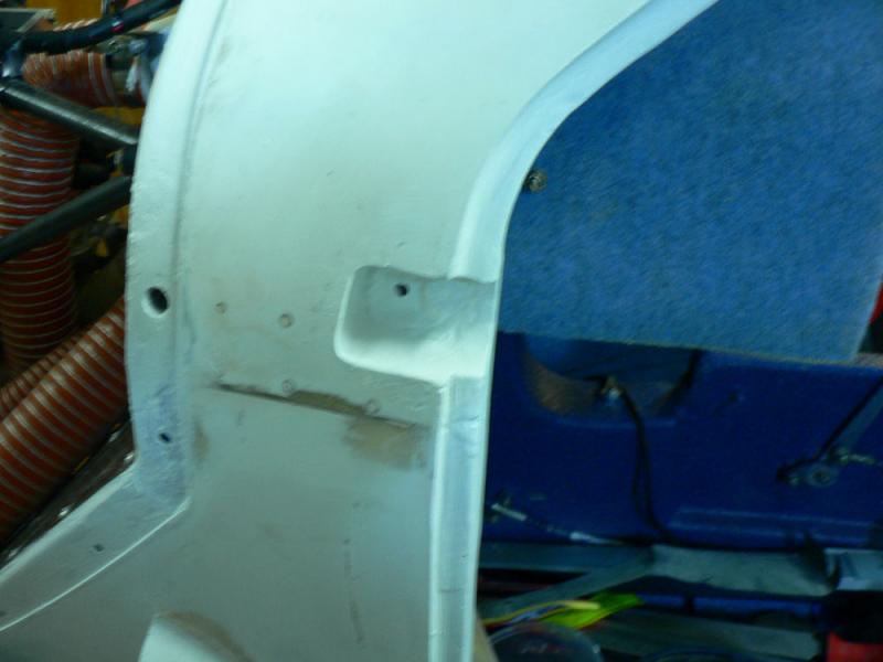
Hand painted the door surrounds, hinge recesses and joggle for the cowls.
New engine bolts not here yet. As they are 2.125 " long they were probably not in stock in Australia.
-
10-06-2008
Replaced the cabin heater scat hose clamps with next size up; far easier to fit clamps in confined space.
Started to attach bottom cowl when visitor arrived who did not help or go home till almost dark!
Tried the trick of screwing one piece of scat hose into the other to make the combination longer. Seems to work well on the small bore scat tube that I tried. I do not plan to use this on the plane.
It needs to be rotated three or four times to screw it into the overlap which would make it difficult to use between two ends where the other end(s) could not be rotated.
The overlap could be made more secure with some super glue but might not even need the glue.
Longer engine mount bolts needed because of the extra spacers inserted between the top engine mounts and the firewall have not arrived yet.
-
9-06-2008
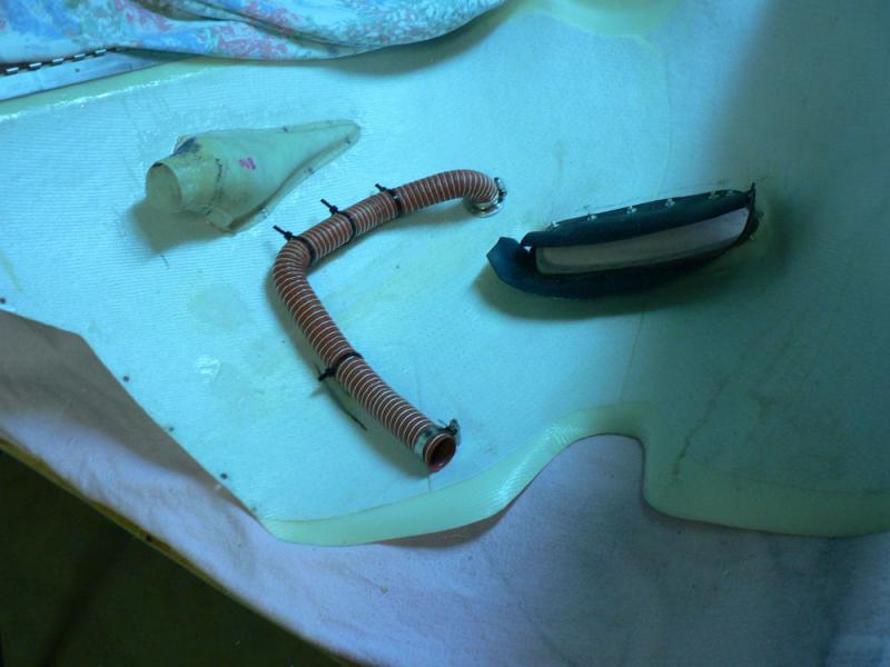
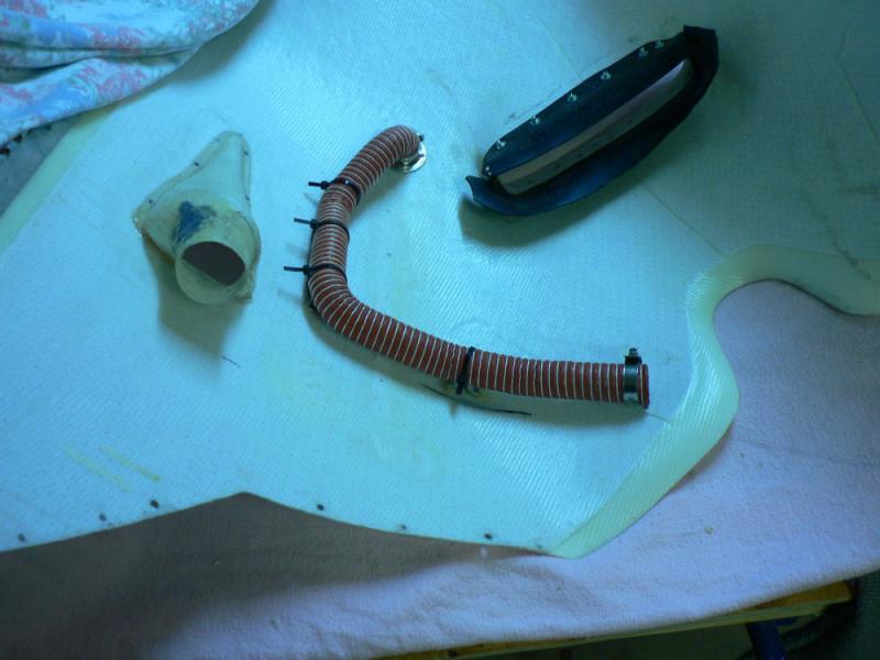
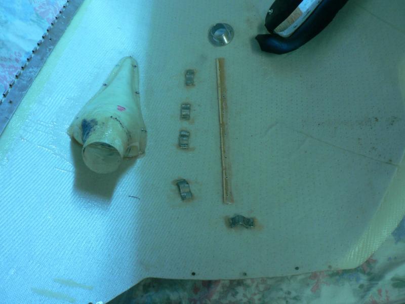
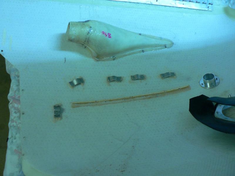
Attached some aluminium saddles to the bottom cowl with flock to locate the air intake for cabin heater further away from the exhaust system.
[ATTACH]5869.vB[/ATTACH][ATTACH]5870.vB[/ATTACH][ATTACH]5871.vB[/ATTACH][ATTACH]5872.vB[/ATTACH]
Added a sleeve to the intake of the air valve to make the connection to the scat tube more secure with the hose clamp.
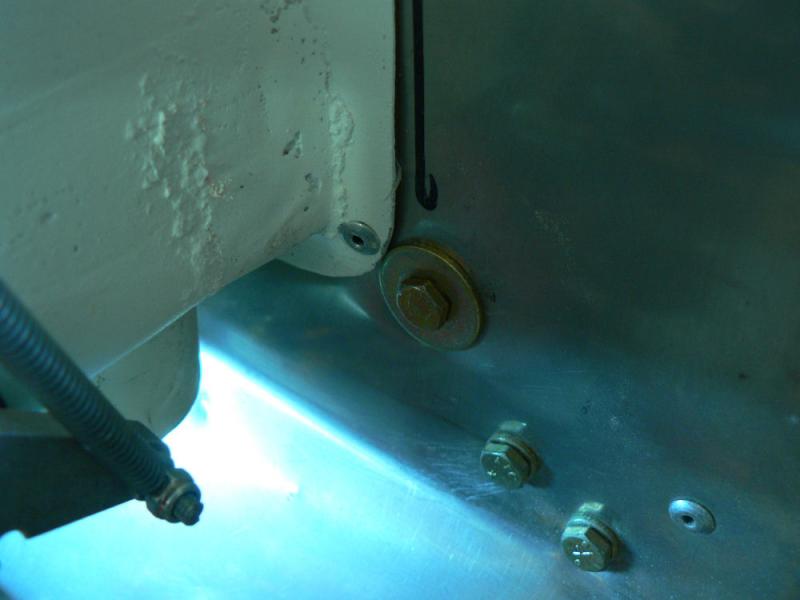
Blocked superfluous access hole through firewall using AN3 bolt, two penny washers and a flat washer with a nyloc nut.
-
7-06-2008
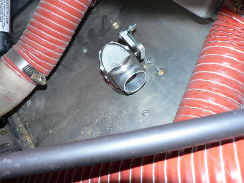
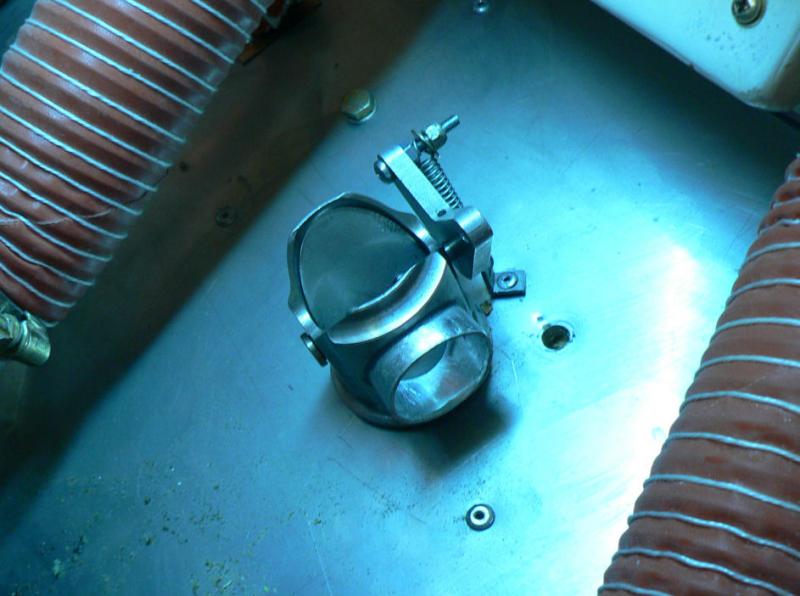
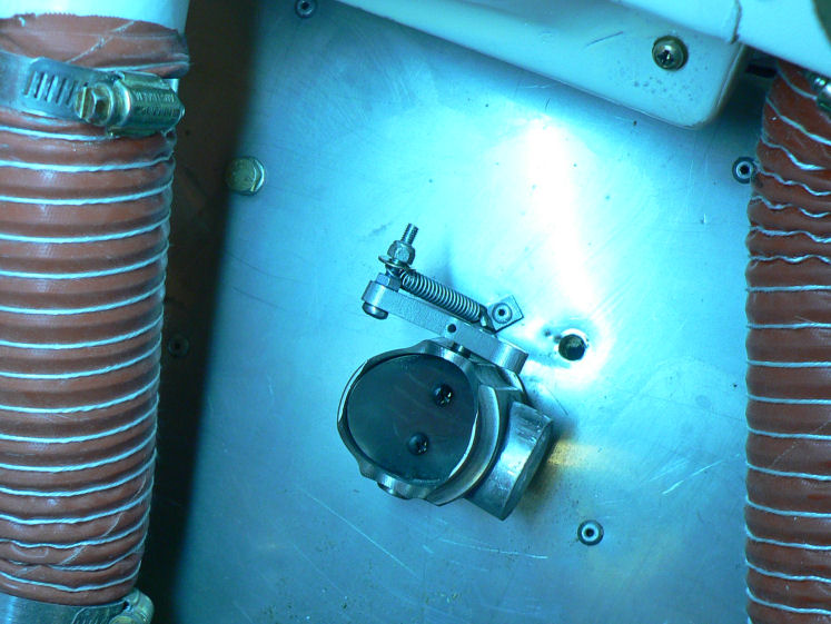
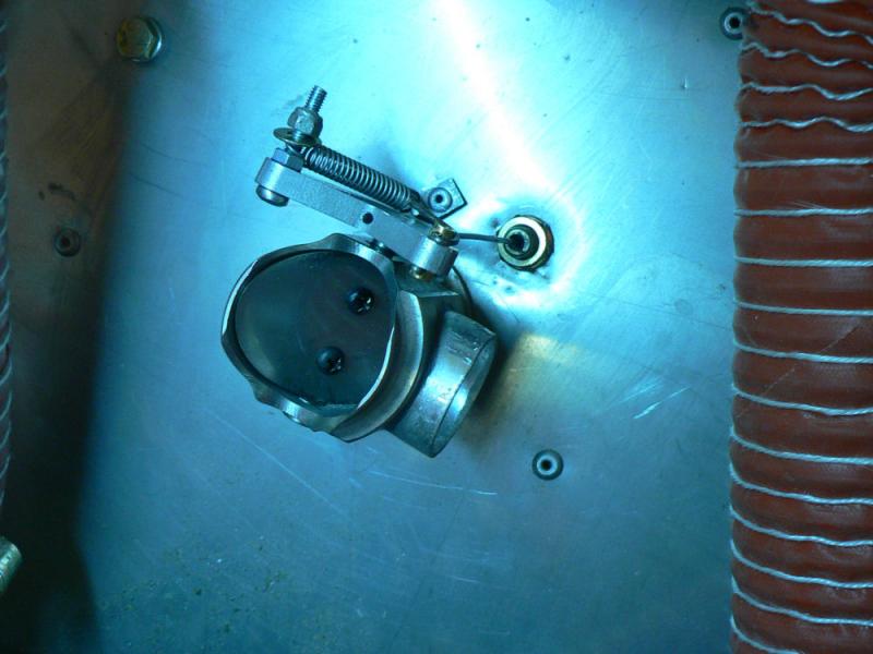
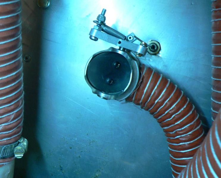
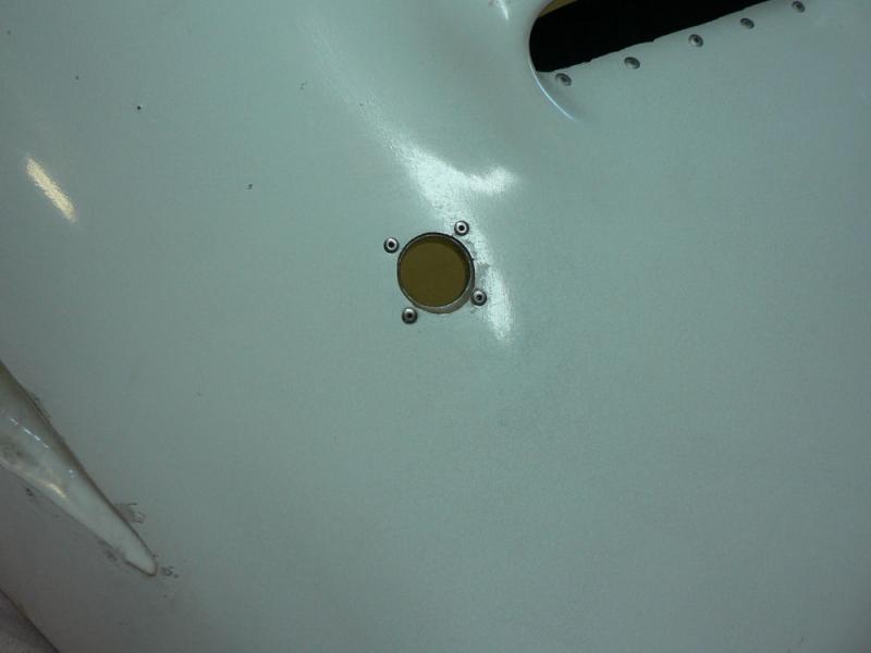
Cut 41 mm hole in firewall with the hole saw as per new manual instructions and inserted the assembled cabin hot air valve after cleaning up the hole with a half round file.
Drilled a 1/8" hole for inserting a SS self tapper to stop the valve rotating in the firewall hole.
Drilled a 1/8" hole for Aluminium angle anchor for over centre spring for butterfly valve.
Pop riveted angle anchor in place with a 1/" pop rivet.
Drilled a hole about 5/16" for cable anchor end for hot air control cable.
Measured and cut inner and outer cable & cover for control cable allowing extra inner cable length to wrap around the brass pivot point.
Attached threaded anchoring end of cable to end of outer cable using Loctite 385.
Put some grooves in outer end to facilitate the loctite connection.
Threaded the cable with a nut and washer at the control knob in the cabin and and inner and outer nut on the threaded cable end.
The inner cable wire was passed through the brass connector and bent around it with hot air valve closed and the control knob pushed almost all the way in. A split pin was inserted into the inner end of the brass pin.
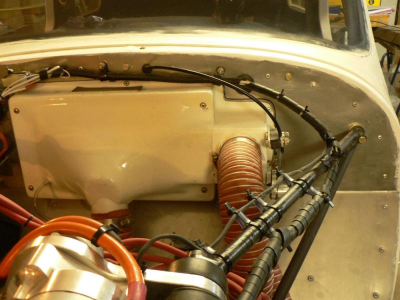
[ATTACH]5842.vB[/ATTACH][ATTACH]5843.vB[/ATTACH][ATTACH]5844.vB[/ATTACH][ATTACH]5845.vB[/ATTACH]
[ATTACH]5846.vB[/ATTACH][ATTACH]5847.vB[/ATTACH][ATTACH]5848.vB[/ATTACH][ATTACH]5849.vB[/ATTACH]
Tried it out looks OK.
Still need to connect up scat hoses tomorrow maybe.
-
6-06-2008
Modified the fit of the neoprene around the air intake of the oil cooler to stop it jamming when the bottom cowl is fitted.
Assembled the metal cabin heater hot air valve.
As the butterfly would not seal in both modes completely it was set it up so that when hot air was turned off it had the better seal and returned virtually all the cabin muff air to the engine compartment.
When turned on it would send the bulk of cabin muff air to the cabin and leak a small amount of heated air back to the engine compartment.
Had to slot the screw holes in the butterfly to get it to fit.
Purchased a 1.625" (41 mm) hole saw to cut a hole through the firewall.
-
05-06-2008
Removed both cowls.
Prepared top cowl for piano hinges by roughing up the area for attaching the piano hinges with rotating emery cloth, cleaning with acetone then priming with resin applied with a narrow paint brush.
The remaining resin was mixed with flock and applied in a thin layer to both hinges which were already drilled for pop riveting.
Five 3/32" CSK rivets were used on each hinge.
The cabin heater inlet was also flocked and pop riveted to the bottom cowl.
All the hinges were checked for excess flock and any extra in the hinge pin area was removed and then the top & bottom cowls were joined using the hinge pins. The combination was sat down with the top cowl on the bottom so that any excess flock would not leak into the pin area.
A fan heater was set up to keep the area warm and a record was kept of the time, temp and relative humidity as has been done on all the previous flocking or fibre-glassing sessions.
[ATTACH]5833.vB[/ATTACH][ATTACH]5834.vB[/ATTACH][ATTACH]5835.vB[/ATTACH][ATTACH]5836.vB[/ATTACH]
A strip of fibreglass scrap was flocked to the inside of the bottom cowl to give a tiedown area for the cabin air intake tube and it was temporarily held down with SS self tappers.
The intake for the cabin warm air does not look good for efficient air intake. It may need some enhancement depending on air flow rate into the cabin.
As has been done with all previous flocking sessions a sample of the flock or resin was taken and put in a medicine measure to set prior to labelling and storage.
-
02-06-2008
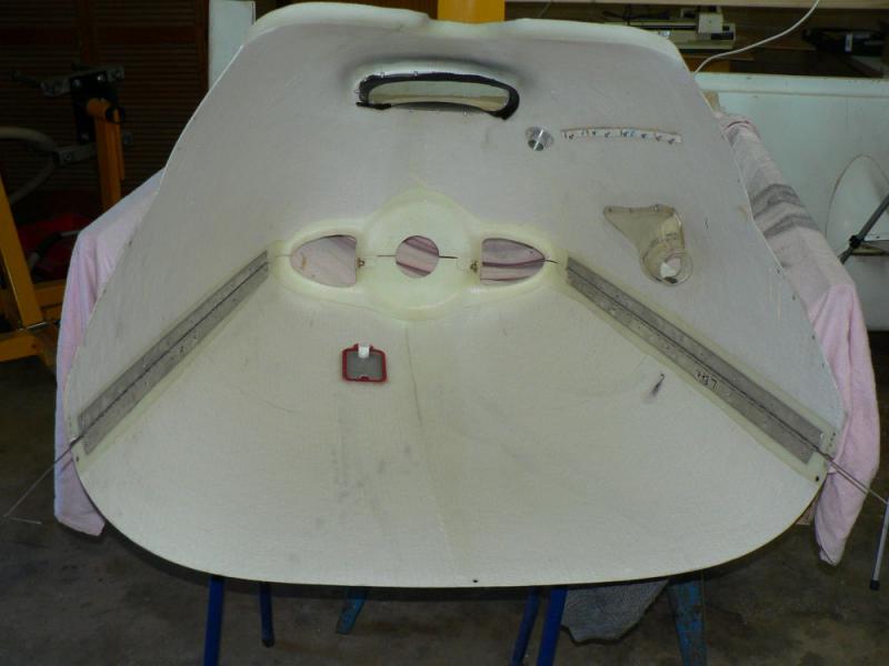
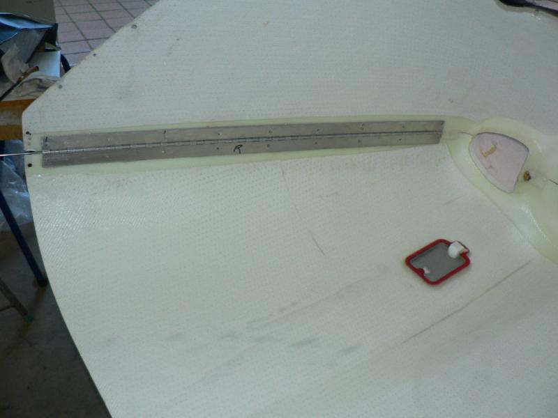
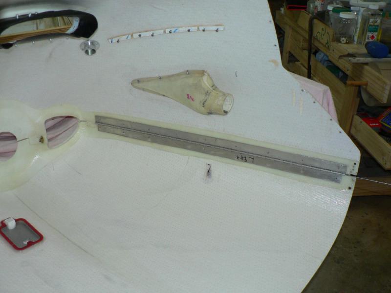
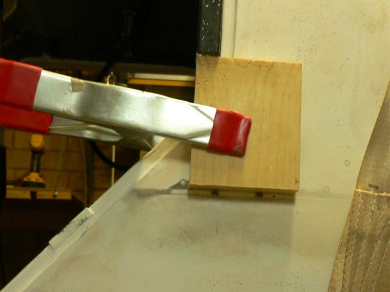
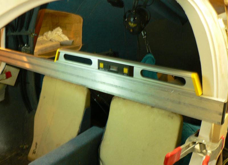
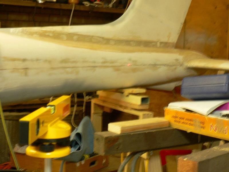
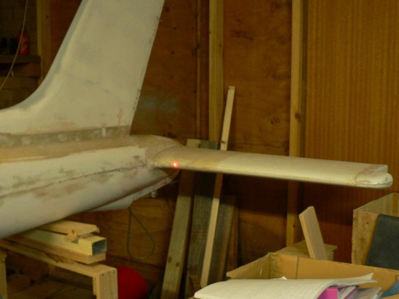
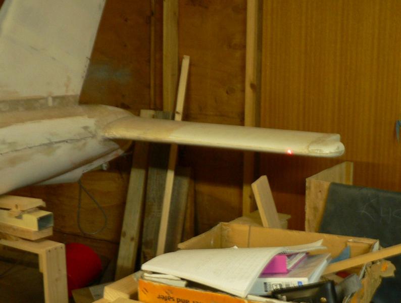
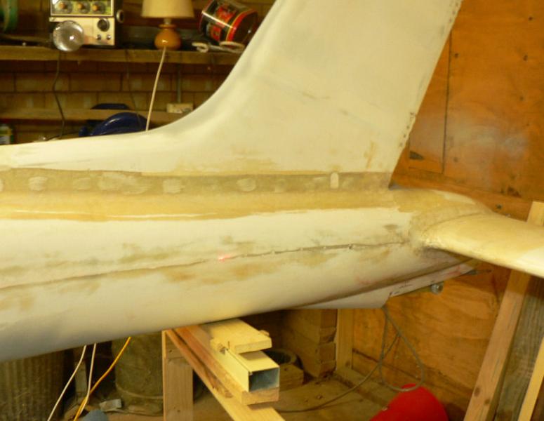
Located the join line of the top & bottom halves of the fuselage on both sides of the A/C.
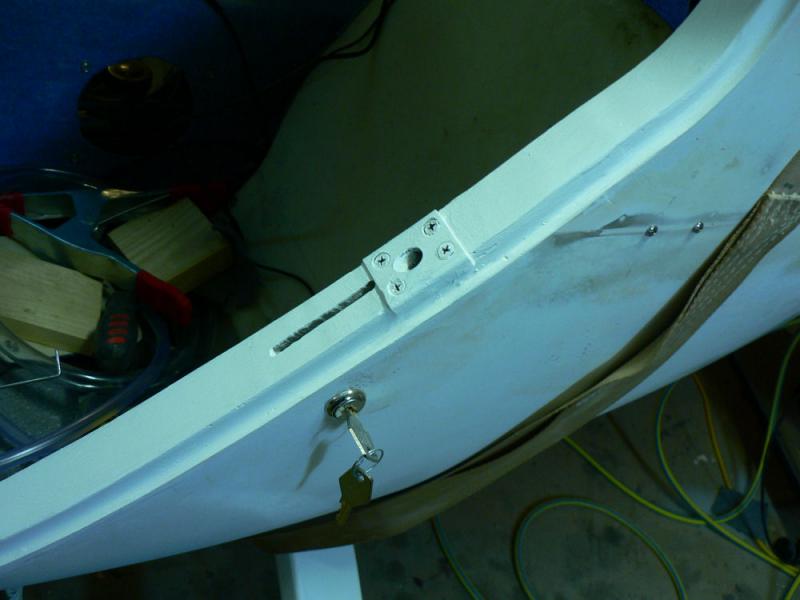
Marked it by inserting two SS self tappers up just behind the door frames about 60 mm apart in the fuselage on each side of the a/c as well as a single one on the join line on each side of the A/C near the vertical stabiliser.
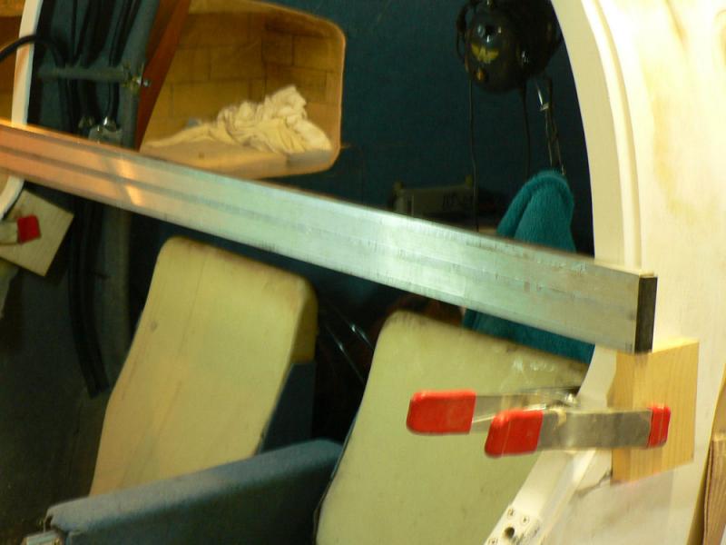
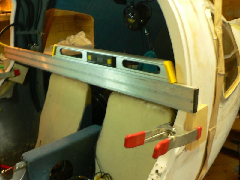
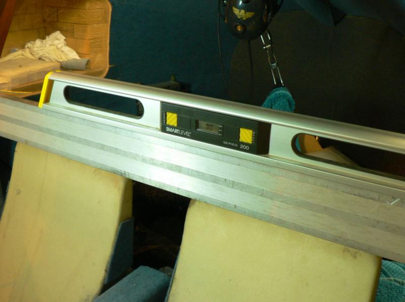
Clamped two even sized wooden blocks on the outside of the fuselage so that they sat on the self tappers locating the join line.
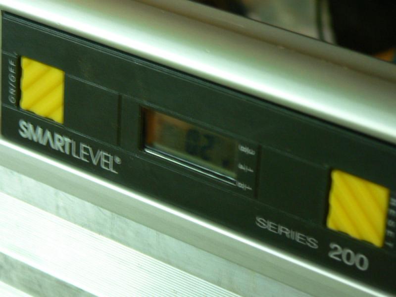
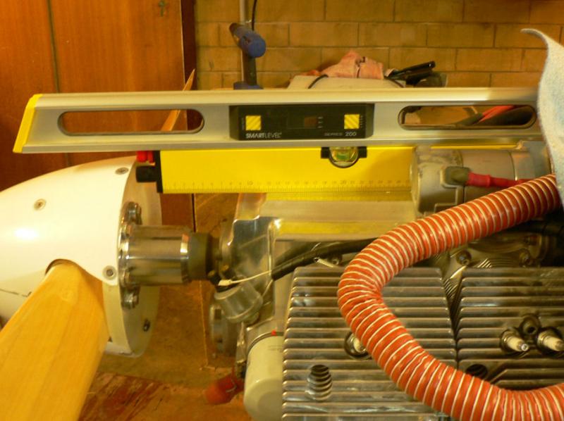
Used these blocks to support a straight edge across the cabin to support an electronic level to level the a/c laterally and the slip & skid instrument.
[ATTACH]5803.vB[/ATTACH][ATTACH]5804.vB[/ATTACH][ATTACH]5805.vB[/ATTACH][ATTACH]5806.vB[/ATTACH][ATTACH]5807.vB[/ATTACH][ATTACH]5808.vB[/ATTACH][ATTACH]5809.vB[/ATTACH]
Had to let some air out of one tyre to get it spot on.
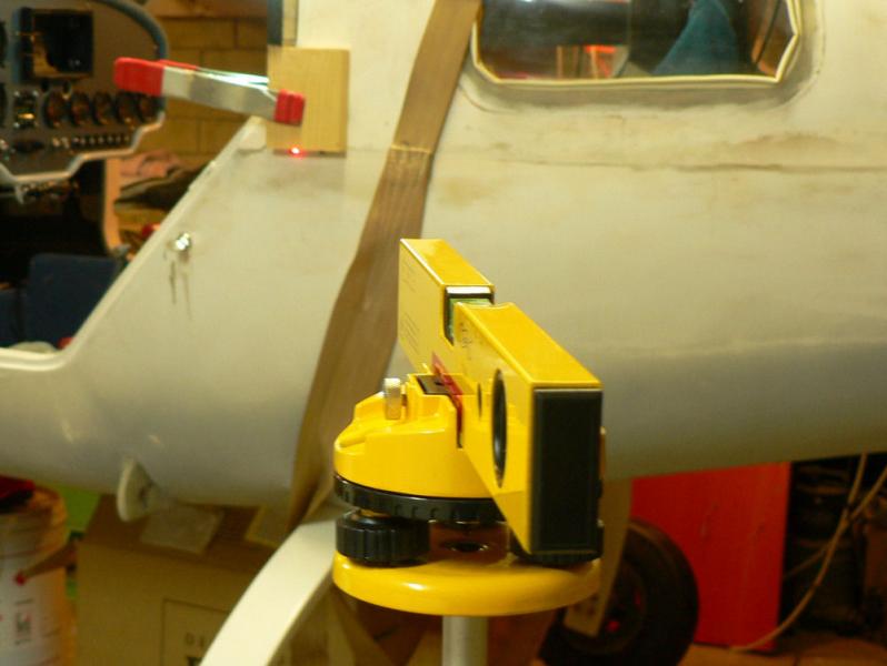
Then levelled the a/c fore and aft based on the fuselage join line with the aid of a laser level, the already inserted SS self tappers and by jacking up the tail slightly to get a level a/c. The tail was already artificially low because the front main U/C wheel was sitting on a few cms of packing.
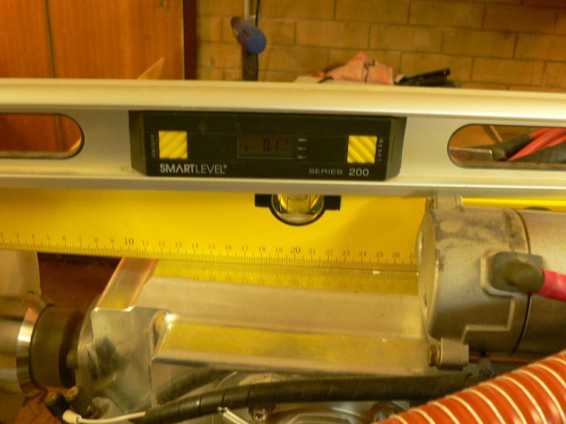
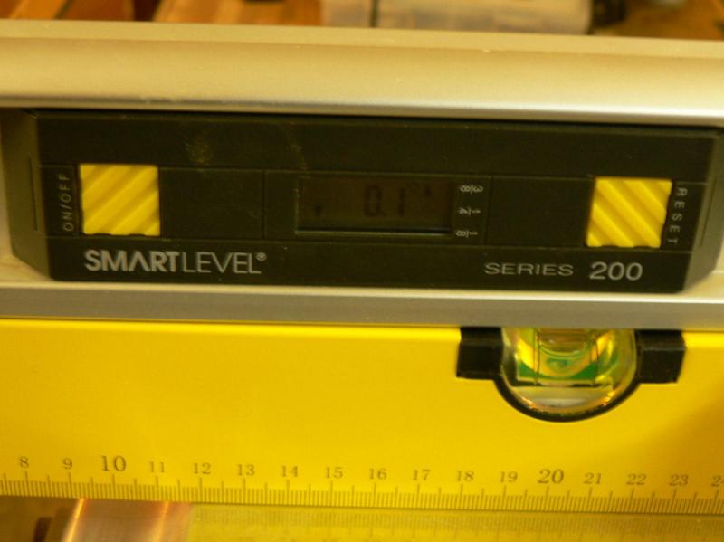
The engine appeared to be too high at the front indicated by the bubble on a level sitting on the top of the motor showing a bubble running towards the propellor - also on the digital level as out by 0.6 of a degree (about 5 mm of the bubble past the level line).
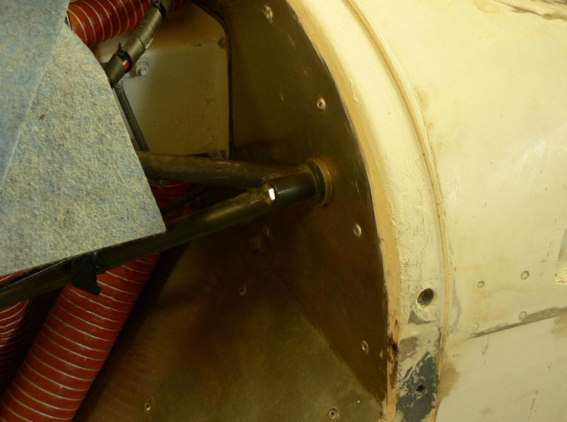
Needed to insert three penny washers under each top engine mount against the fire wall to reduce the error down to 0.1 of a degree high at the prop end of the motor.
This might reduce a bit after a few hours of engine use.
[ATTACH]5810.vB[/ATTACH][ATTACH]5811.vB[/ATTACH][ATTACH]5812.vB[/ATTACH][ATTACH]5813.vB[/ATTACH][ATTACH]5814.vB[/ATTACH]
[ATTACH]5815.vB[/ATTACH][ATTACH]5816.vB[/ATTACH][ATTACH]5817.vB[/ATTACH][ATTACH]5818.vB[/ATTACH][ATTACH]5819.vB[/ATTACH][ATTACH]5820.vB[/ATTACH]
The pics shown of the levels on the engine were all taken after inserting the three penny washers under each of the top engine mount bolts against the SS firewall.
According to the manual we are already on the limit of three for the number of washers inserted under an engine mount.
According to my measurements I need to replace the AN4-2A top firewall engine bolts with AN4-21A bolts as the bolts barely emerge from the lock nuts with three penny washers fitted.
-
Today a new Tecnam P92 from Wagga dropped into Narrandera on the way back from a couple of days of demonstration flights at a couple of more southerly aerodromes. After a refreshing cup of coffee he departed back to Wagga.
The demo pilot from Wagga said they are now the Australian agents for the range of Tecnam aircraft.
Wally was not ready to turn his J230c over for a P92.
Narrandera afternoon had a near vertical windsock for most of the time. So I had a fly of Wally's J230c to do a few circuits from runway 32 and a climb to 4,500 AMSL where it was nice and cool and very close to the top of the inversion.
There seemed to be a lot of circuit activity at Shepparton which I could hear on the radio.
-
This one seems to have a way of growing itself.
Even through RAAust the fee is now $160 according to their downloaded forms.
I submitted documentation for my ASIC renewal through Wally Rudin last week at Narrandera and was not required to send off my old ASIC card before the new one arrives. I posted it off to the RAAust in Canberra.
It will be interesting to see how long it takes to arrive and what they want to do with the old card.
-
29-05-2008
Drilled out the rivets holding the piano hinges to the bottom cowl and prepared them for flocking to the cowl. This is not the method according to the new Jabiru construction manual and I don't recommend it.
Prepared the hinges with emery cloth and acetone also the matching area on the cowl.
Applied mixed resin to the cowl join area and then mixed flock into the remaining resin and applied a thin layer to the piano hinges.
Fitted the piano hinges to the cowl pulling it in with 3/32" CSK pop rivets using 5 rivets on each hinge. Cleaned up any dribbling flock on the inside of the cowl and spread it along the bottom edge of the hinges.
Cleaned up any flock intruding into the hinge holes on the top edge of the hinges.
Also inserted the hinge pins making sure that any flock is not spread along inside the hinge holes. This will help to keep the alignment of the hinges.
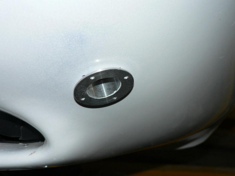
Marked out and cut the hole for the cabin air intake into the front of the cowl. Used a 29 mm hole saw and filed out the hole until the aluminium flange fitted in the hole.
[ATTACH]5779.vB[/ATTACH][ATTACH]5780.vB[/ATTACH][ATTACH]5781.vB[/ATTACH]
Used the flange as a template for drilling the rivet holes.
The flange will be mounted inside the cowl - not outside as shown in the pic.
-
At Griffith:-
The only intruders that were written up in recent years were some Kangaroos that did not know they were not allowed on the main runway and caused a light plane to have major trauma.
My only personal experience of intruders were some unsecured galahs, maybe 20 or 30 of them, that decided to take off across the main strip in front of me just after I was getting airborne in a Jabiru probably about 50 feet up - lowered the nose, cut the throttle and went under them then plenty of strip left so continued the takeoff.
-
On the local TV news tonight 28-05-2008 a police task force was shown in the process of reviewing the security of Griffith airport.
Griffith AD is a security controlled Airport. CTAF-AFRU 126.55®
There was also an announcement of an upgrading of the RPT terminal and the lenghthening of the main runway from 1503 m to 1700 m and the installation of a taxiway presumably for the full length of the extended runway. I hope the taxiway will be capable of taking the RPT aircraft the full length of the main runway.
*************************
According to the TV news, the task force is due to review Narrandera airport security tomorrow 29-05-2008.
Narrandera AD is a security Controlled Airport with main runway at 1616 m in length. CTAF-AFRU 126.7
-
28-05-2008
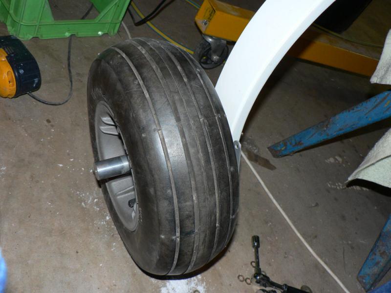
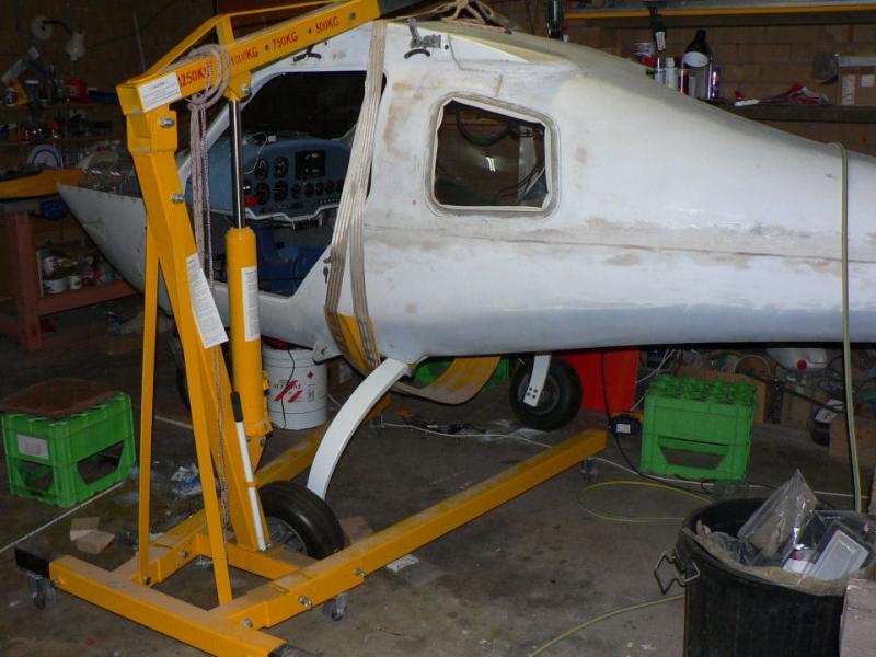
Lifted the AC with the hoist and removed the starboard main UC wheel and stub axle.
Removed the wheel from the stub axle and deflated the tube.
Undid the bolts to split the wheel but the tyre did not want to let go of the rims despite the use of a couple of good tyre levers and a 6" vyce which would open just far enough to allow the tyre to be inserted and squeezed.
Eventually got the tyre off the rims by lubricating the area with detergent and water on the inside and outside of the tyre. I think some detergent and water will be part of my tool kit as well as the tyre levers.
Removed the tube.
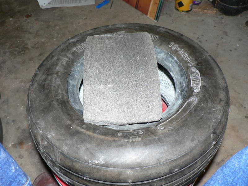
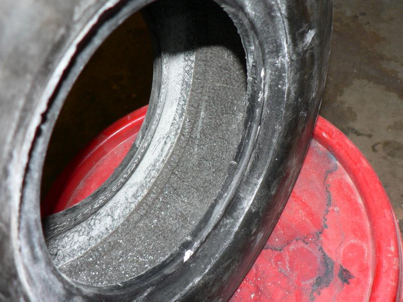
Lined the tyre with foam making sure it was long enough to need some compression to fit in the space making the two ends so that there will be no gap.
Replaced the tube and partially inflated it to prevent pinching by the rims grabbing it during assembly.
Applied talcum powder to tyre and tube to ease fitting of rims.
[ATTACH]5771.vB[/ATTACH][ATTACH]5772.vB[/ATTACH]
Refitted the split rims and bolted them together after taking care to align the valve teat and the bolt holes.
Enlarged the 1/4" holes in the brake pad mounting plate to 5/16" to suit the new axle bolts.
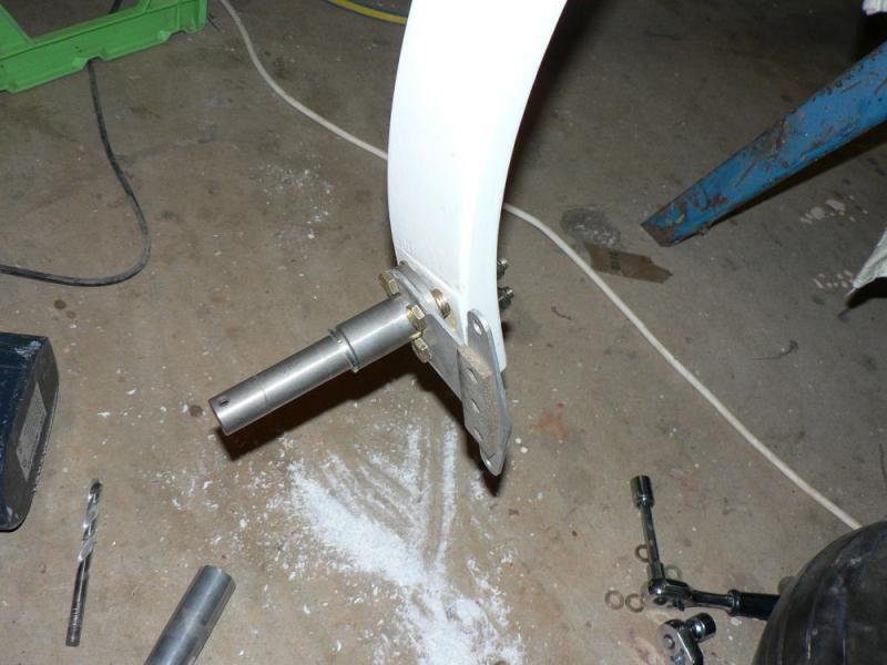
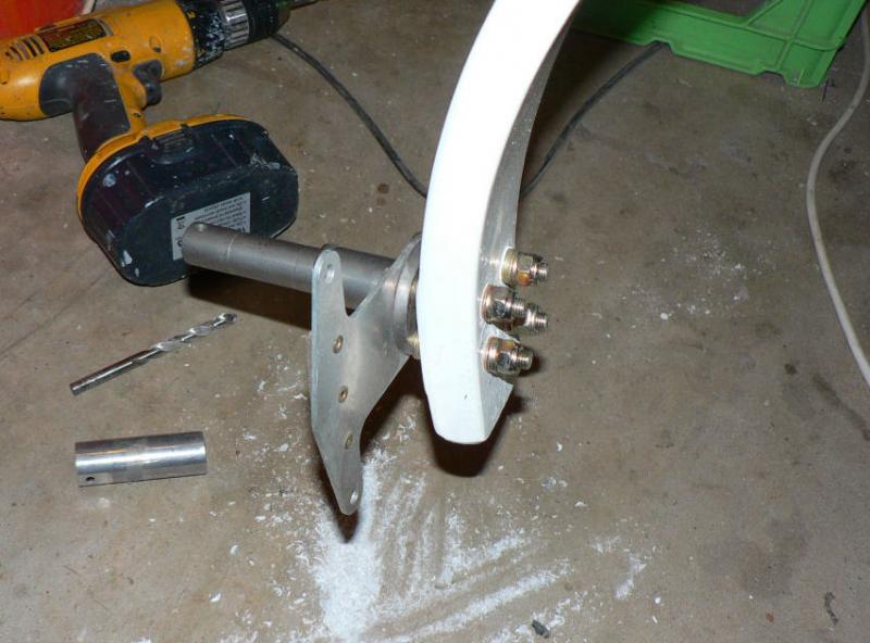
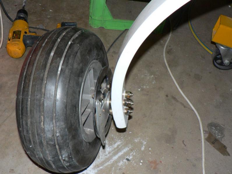
Fitted the new stub axle after drilling out the bolt holes in the UC legs to 11/32" and bolted it up with NA5 bolts and washers to an approximate good wheel alignment as done previously.
Only need one spanner to do up bolts on the new stub axle because the bolt heads are stopped from rotating by the axle.
[ATTACH]5773.vB[/ATTACH][ATTACH]5774.vB[/ATTACH][ATTACH]5775.vB[/ATTACH][ATTACH]5776.vB[/ATTACH][ATTACH]5777.vB[/ATTACH]
Will need to check the wheel alignment again after the plane is loaded with wings and fuel. Washers could be replaced with flock filling or fibreglass packing depending on the size of packing required.
Fitted the wheel back on the axle with the keeper on the outer end of the axle.
Let A/C down off hoist and tried moving it - moved about 12" easily on wheels - so far!
No sign of any conveyor belt under the A/C.


Poor cranking - my problem resolved.
in Jabiru
Posted
Wally at Narrandera was telling me that about a 5 minute stint with a hair dryer sitting on the inside edge of the lower cowl outlet will let his J230c start with just a touch of the starter button on these cold mornings lately. It would soon heat the whole outside of the engine and get the chill off the oil after a few minutes.