Ross
-
Posts
729 -
Joined
-
Last visited
Content Type
Profiles
Forums
Gallery
Downloads
Blogs
Events
Store
Aircraft
Resources
Tutorials
Articles
Classifieds
Movies
Books
Community Map
Quizzes
Videos Directory
Everything posted by Ross
-
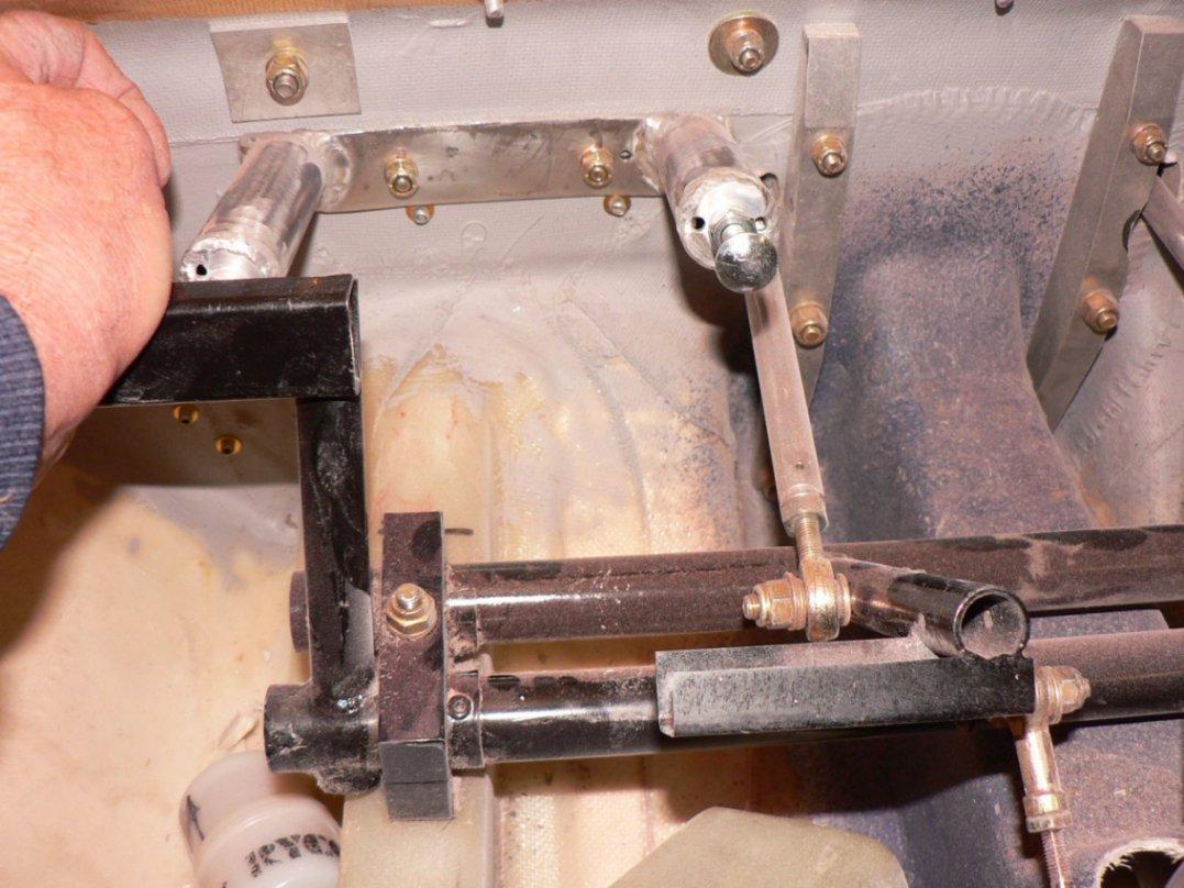
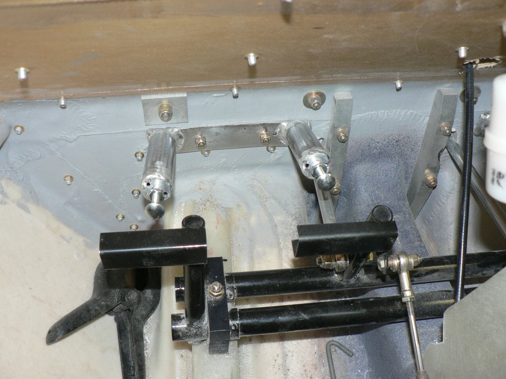
Hi Michael I just took another quick photo a bit closer with macro with plenty of dust on everything. The rudder is not actually connected in this pic but the stops are set roughly in the right place. I think that shows what you mean about the pedal gusseting hence my mounting the stops to minimise the load at full travel. It doesn't solve the problem of two sets of legs working in opposite directions though. They are Jabiru supplied pedals with test certificate. [ATTACH]807[/ATTACH]

-
Hi Michael I set the pedal stops up so that the middle of the hollow back of the pedal, not the pedal post, arrives on the top of the cup head bolt (stop). The line direction of the bolt stop is approximately a tangent to the arc of the pedal movement when it connects. This should reduce the tendency of the bolt stop to bend under the load of the pilot when the pedal bottoms on the stop. The position of the stop on the pedal reduces the potential load that can be put on the welds holding the pedals to it's support. While in the air, the maximum load on the pedal linkage etc should only be that required to move the rudder unless you are having an argument with your passenger. In gliding, sothe story goes,this only happens when two instructors are flying (together)in a Blanik (in tandem seats). It reduces the chance of the pedal slipping past the stop. There is another set of stops for the passenger side pedals and a set of fibre glass stops at the rudder as well. The latter work on the rudder thus protecting the cable if the cabin stops are set correctly. For all this to work safely to protect the pedals with their welds (they come with a test certificate), the push pull cable and the rudder itself all the stops must be set up to match one another with the correct allowable travel for rudder cable, angle of rudder and angle of turn for the front wheel. The spring loaded rods to the front wheel are set to centre the front wheel with the correct angle set on the rudder and the rudder pedals centerd. Trimmed correctly etc the J160 should cruise ok with feet off the pedals. That will be different. My apologies if these explanations of my actions here are too much - this is one the difficulties of communicating using the internet. Regards
-
Hi Ian I think perhaps the problem was that I tried to edit the posted item while you were moving it to the new location. I presume that the system effectively had it locked against me until the move was completed - otherwise chaos. In 2007 I think I probably double clicked in IE6 and had two copies running therefor locking the file for the second copy. Thanks Ross
-
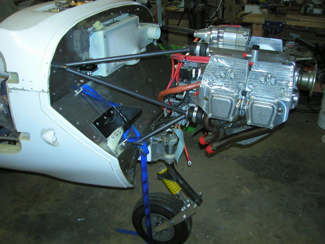
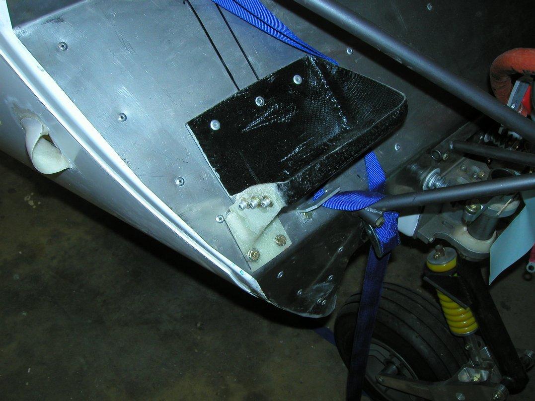
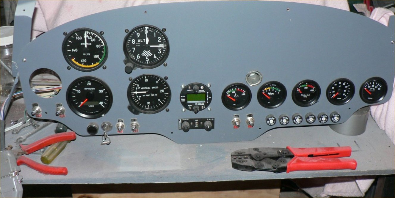
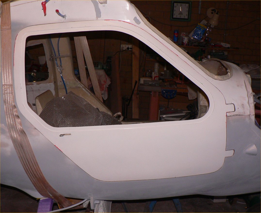
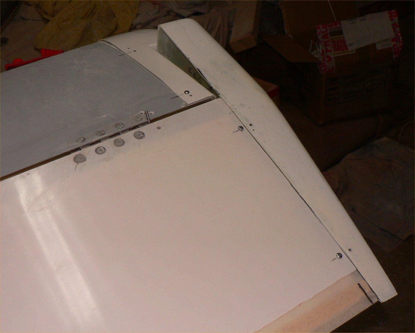
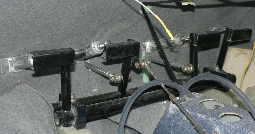
Hi Crew A few more pics. These rudder pedal stops will need a bit more material underneath perhaps a piece of equal Al angle welded to the base and up the side of each tube. Rudder pedal Stops Engine Side firewall [ATTACH]801[/ATTACH] [ATTACH]802[/ATTACH] Battery Holder modified so that the battery can be removed w/o Simple panel. removing the engine mount. [ATTACH]803[/ATTACH] Simple to install. [ATTACH]804[/ATTACH] Cable controls to be installed below Al instrument panel. [ATTACH]805[/ATTACH] I was worried about fitting the doors having heard horror stories about fitting them but was pleasantly surprised with no heating or bending done on this door so far. RH side of Horiz stabiliser with end cap almost prefitted RH side elevator hinge pop riveted and epoxied w/o hinge pin retainer fitted yet RH side of elevator with mass balance end cap almost prefitted [ATTACH]806[/ATTACH] To be continued .... Ross
-
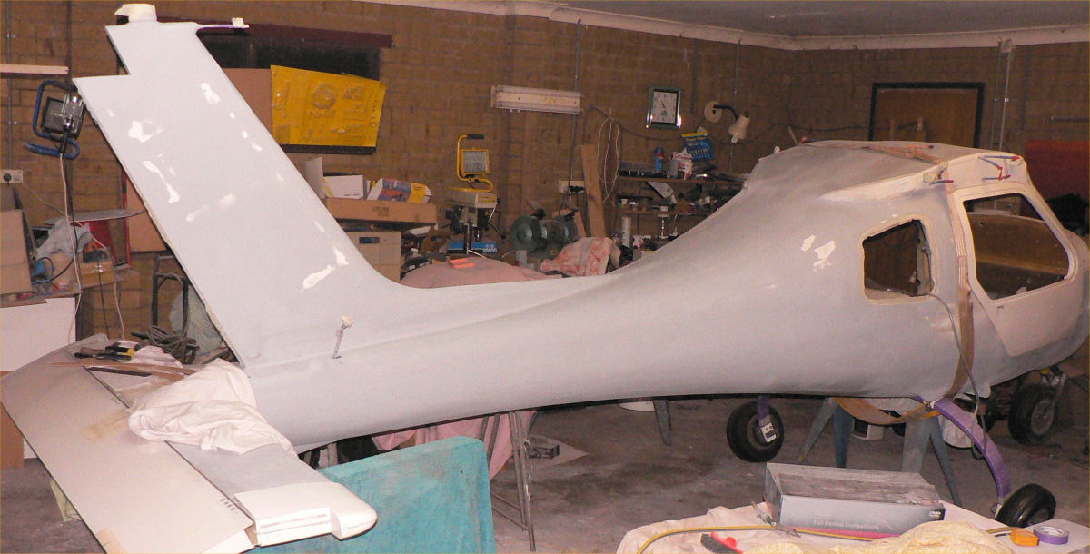
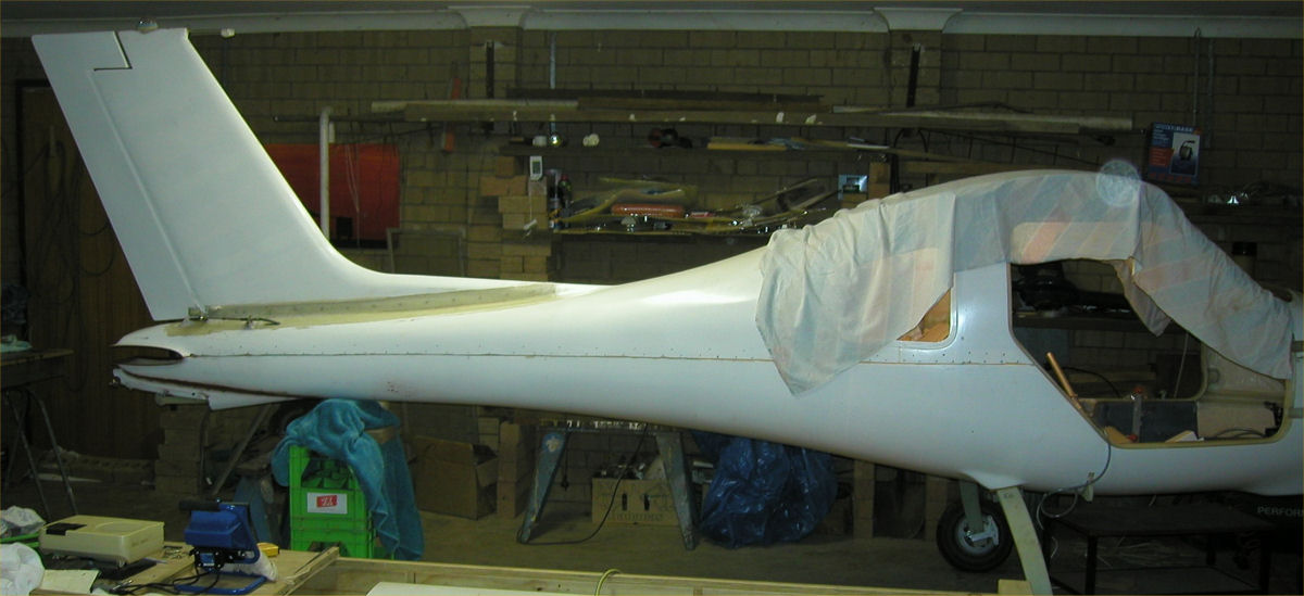
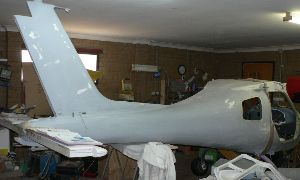
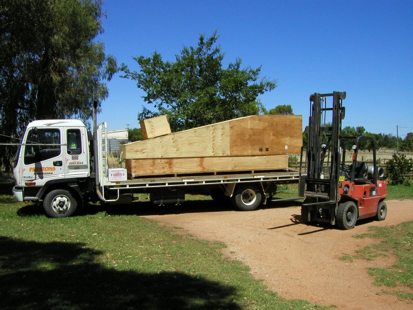
The kit, in three wooden boxes secured together, was sent by road from Bundaberg to the agent of a Leeton carrier in Brisbane about 300 km I think from where it was back-loaded to Leeton about 1350 km on a semitrailer and then transferred to a smaller truck & delivered to our place. [ATTACH]837[/ATTACH] Jabiru J160 about to be unloaded - Note the normal sky colour At this stage the hull join, horiz stabiliser join and vertical stabiliser have been smoothed by filling with epoxy micro-balls and undercoat filler sprayed with a couple of coats. What you can see has then been sanded and refilled where necessary.There is plenty of spraying and sanding still to go with most of this undercoat to be sanded off. [ATTACH]832[/ATTACH] [ATTACH]831[/ATTACH] [ATTACH]835[/ATTACH] Inside all the control levers in the cabin have been fitted; rudder pedals with 4 pedal stops, rudder cable with stops aft on fuse & verttical stabilizer, elevator control lever and cable, trim lever and cable, aileron lever, flap handle & cross shaft, hand brake handle with ratchet stop & master cylinder, engine throttle lever & cable. The fuel lines with valves for each tank and sight gauges (wet wings) have been fitted in the cabin, still to finalise the header tank. Electric fuel pump & filter have been fitted. [ATTACH]833[/ATTACH] [ATTACH]836[/ATTACH] This one is a lot later with the base of the rudder pedal stops stiffened up with an extra layer of Al strip and the firewall has now got a layer of foam and felt glued o it. Static line and strobe wires have been run to the top of the tail and a pitot line has been threaded from the panel area under the passenger seat through the hull near the hull strut connection point long enough to reach the pitot tube to be installed in the right hand side strut. The main UC has been sanded, undercoated and final painted and fitted to the hull with larger bolts than originally specified. To be continued maybe....!
-
Hi Geoff Your enquiries will be welcome. But I am no expert. I have plenty of photos. Our J160 kitwas delivered on about 14thDec 2004 and is number 14 of the J160 series with wet wings and mechanical tappets. I had a major interruption to the work from June 2005 till March 2006 but now have no excuse aside from family & friends visiting occasionally. Geoff Waddleton from Mildura helped by sending photos of various parts. Not having anybody to talk to about it was a major obstacle. It took me a while to make the contacts forfinding infoon handlingepoxy, filling rough areas, paint, aircraft grade bolt supplies, sandpaper grades and solving some of the problems while building the aircraft. The factory people were very helpful and will give advice on any area required. One of the troubles was the quality of the English in their construction manual whichwas better than Japanese English but did result ina number of vague instructions. For handling the epoxy mixing I obtainedand old set of Post Office Scales, $20, without weights.I use about 50 only5/16" nuts as counter weights so that many different sizes of mixes can be done in a ratio of 3 epoxy to 1 of hardener by weight. If the mix is too large, because it is exothermic when mixed, its temperature rises rapidly giving off poisonous fumes. It also rapidy sets when the temp is raised above about 25 degrees C resulting in a loss of the batch unless it is cooled artificially say by sitting the mix on a cold pack. I have found it easier to simply use smaller mixes. Jabiru said that the setting process, if interrupted by low temps about 15 degrees C I think, will continue once the temp rises again. Because it is a chemical reaction it is important that the epoxy and hardener be mixed in the correct ratio accurately.Thisinterrupted setting is typically the case if abatch is mixed and used late in the afternoon followed by a rapidly cooling evening. It does need some hours at the right temp to set to full strength, maybe 12 hours. Of course this can be helped by raising the temp with say fan heaters.Wagga is a bit colder than Leeton. The fuelage is half painted with a high fill paint to fill the pin holes,the bare fibreglass areas and the joins which I have alreadyfilled with a microball epoxy. The microball epoxy was not used structurally only as a filler.It is fairly easy to work. I initially, after setting,use a paint scraper with a carbide blade on the filler then a rectangular random sander. The firewall is fitted after I made a wooden folder to fold it in two places. The engine mounts are painted and fitted. The engine has been mounted a couple of times and a quick release G type clamp modified to facilitate compressing the engine mount rubbers while doing up the mounting bolts. I purchased a manual hydraulic"engine crane and engine stand" to facilitate handling the aircraft fuselage and the engine. I got a sling made to lift the fuselage. I made an adapter plate for the separate engine stand so that the engine can be mounted on it using the engine mounting holes and simple clips ( narrow three point linkage typeclips) to secure the engine on the stand. The stand has been modified so that I can rotate and lock the engine in 90 degree steps around its longitudinal axis. Gotta go. More later if you want it. Regards Ross