
pluessy
-
Posts
130 -
Joined
-
Last visited
Content Type
Profiles
Forums
Gallery
Downloads
Blogs
Events
Store
Aircraft
Resources
Tutorials
Articles
Classifieds
Movies
Books
Community Map
Quizzes
Videos Directory
Posts posted by pluessy
-
-
the fuel flow is controlled by that little lever near your hand. The prop is only trying to resist your command.
The Bing is no different to any other carburetor other than having a variable venturi instead of a fixed one. The throttle plate (butterfly) controls the air volume and the piston moves to vary to venturi to add the correct amount of fuel.
A fixed carburetor has a number of passages and jets (air bleed, emulsion tube, enrichment etc) to do what the piston does in the Bing.
-
 2
2
-
-
3 hours ago, Thruster88 said:
I have always wondered about this. We know with Lycons above 7500 feet we usually have the throttle wide open (FT) as the chart I posted above shows.
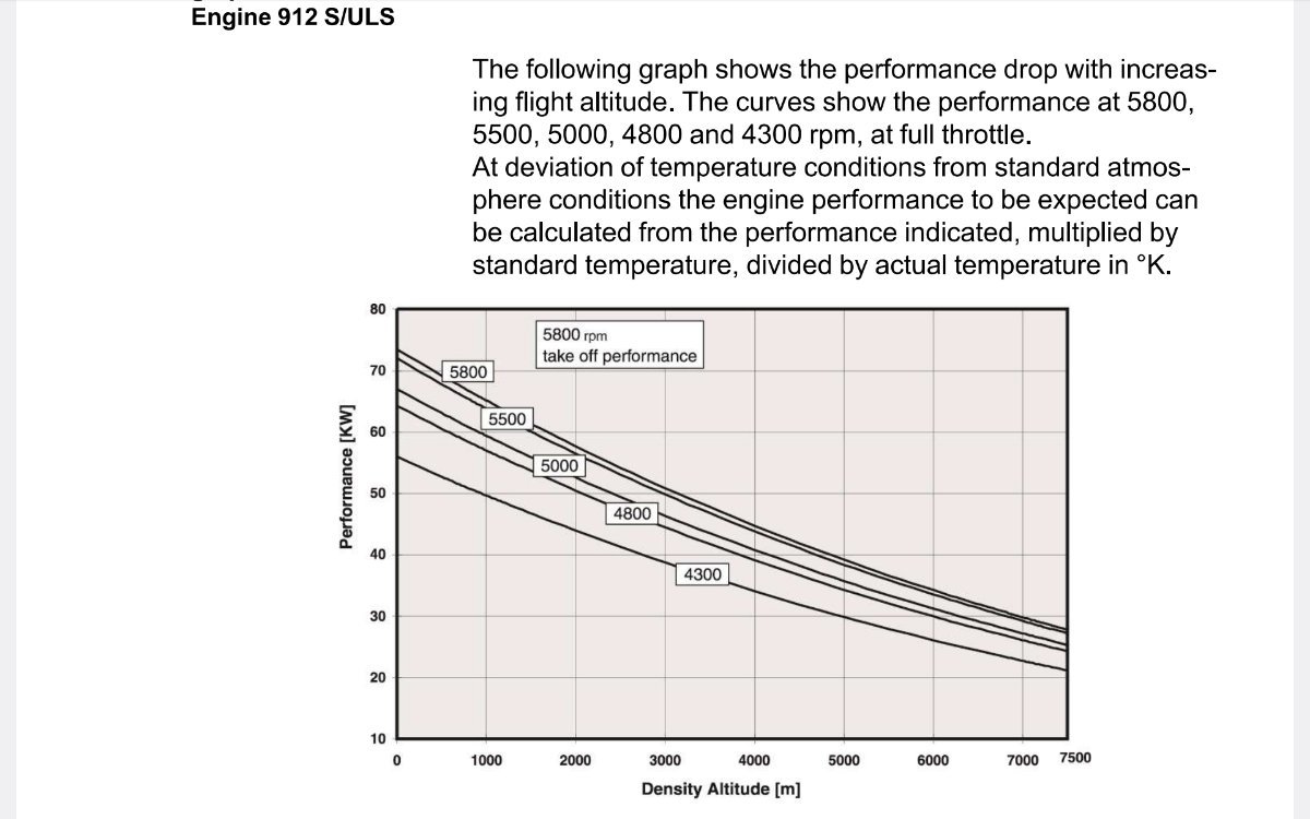
The Rotax 912ULS performance chart at altitude shows the 100hp engine only making about 38 hp at 7500 feet when it should be capable of approximately 75hp at that altitude. What is going on in that carburetor??? Is the chart wrong?

Density altitude is in METERS, not feet. 7,500' is about 2,300m and the power at WOT and 5,500rpm is around 56kW (or 75hp which is your 75% of sea level max power). Same difference, different units.
-
 1
1
-
 1
1
-
-
There are some hangars in Atherton that might have space, I have my plane in one of the big hangars. Don't know about Herberton, there are quite a few hangars but I have no contacts. Some of the members of the Atherton Aero Club might be able to help (put up an ad here: https://www.athertonaeroclub.org/classifieds).
-
There are a few trikes parked in a hangar in Atherton, there was also a trike school but can't find any info now. Your nearest airstrip is Herberton (YHTN), 1/2 way between Herberton and Wondecla, Tablelands Regional Council owned (https://www.trc.qld.gov.au/services-and-facilities/aerodromes/herberton-aerodrome/).
-
16 minutes ago, Thruster88 said:
What is a one way strip?
A landing strip where you land, turn the aircraft around and take off in the direction you came from. Many one way strips have rising ground or other obstacles at one end that can make it impossible to complete a go-around. Look at the topographie of the "Finch Hatton strip", mountain on the S side that you will not outclimb.
-
1
-
-
Check your metering needle and seat for wear, they need replacing after a while. Worn needle & seat are causing richer mixture in the part-load range. On aircraft, you will find a worn spot where the piston/needle sit at cruise power. The needle should be a smooth "taper" all the way and the seat a round hole (worn seats are oval).
-
2 hours ago, Freizeitpilot said:
Silent Hektik regulators get a mention on a European ULM forum. I know less than zero on this subject, but just thought I’d mention it in case it is remotely useful to someone here.
I note they have a presence in Australia.
I think you got the wrong company, no regulators in their offering?
-
I have a PDF copy if you are interested?
-
My plane got hit by a hailstorn in Narrabri, parked outside. The damage was on top and down one side (strong wind), so make sure you have the sides covered as well or enough distance to the edge.
-
2
-
-
With P92, trim for about 55kts on final and use the throttle to control the descent. The when you come close to the threshold, very gently pull back to reduce the sink rate and just let her settle down. I usually pull a little bit more back just before the wheels get on the ground and pull the power at the same time. The keep pulling back to keep the nose wheel just off the ground till that settles as well.
Trimming for the correct speed takes one variable out.
304 landings and only one bent gear leg🙂 (2 up, spot landing comp👎)
-
1
-
-
If you make your own tester eg the cheapy or a modifed version, then the OEM specs are meaningless!
As already pointed out, the leak-down test is overrated. Do a dynamic compression test and track that. Quicker, simpler and more accurate representation of the internal condition.
-
1
-
-
1 hour ago, skippydiesel said:
As I keep saying EPOXY - just use some HD epoxy, to plug the existing hole and then carefully drill with a 1mm bit - there is no need to drill out/enlarge what you have and then fit a plug with a 1mm hole. This aperture is for relativly low pressure air, without abrasive characteristics and as an amature, infrequent use, tool does not warrant the effort of redoing it in metal. If achieving the same result in metal makes you happy - go for it!
FAA - Australian???
Inches - Australian???
I agree with leaving the tester as is - as mentioned earlier - the leak down test is primarily a comparative one ie record an initial reading, then compare all future reading with this, noting changes.
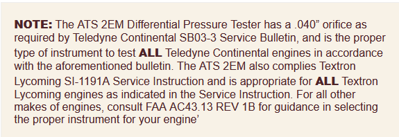
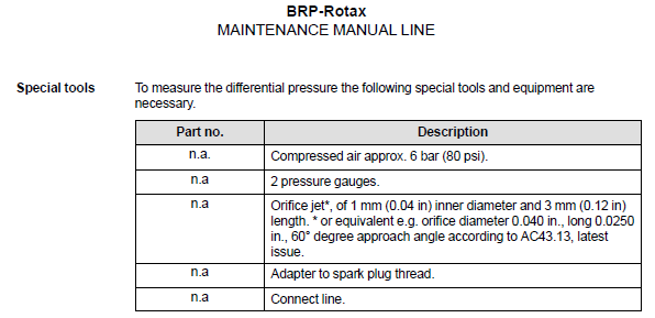
IF you want to make one that meets the FAA spec (AC43.13 1B), then you need to make the orifice to spec and insert it. Filling the hole with epoxy and drilling 1mm will give you something close, but not as per spec (the OP requested 1mm orifice, so I take that as "FAA spec"). Because the FAA did give that spec, it is the standard in the aviation engine industry. The 2 major engine manufacturers (and Rotax) refer to that:
-
2
-
-
1 hour ago, Admin said:
Clear Prop also has another version and currently in stock which is cheaper as well:
Engine Cylinder Leakage Tester
WWW.CLEARPROP.COM.AU
Heavy duty cylinder leak-down tester Features This automotive compression tester works with most car models and gasoline engines...This is the compression tester, not leak-down
-
 1
1
-
-
same as the one I have. Remove the regulator, drill out the hole, make a suitable orifice (0.040" dia x 1/4" long) and insert to meet the FAA spec. The existing 1.5mm hole will give you good results, though🙂
-
Just checked my automotive leak down tester (similar to the Toledo/ToolPro), it has a 1.5mm drilling in the body. To make it relevant to the aviation test, I would need to drill that out and put in a 1mm bush/jet.
Also read this: https://www.aopa.org/news-and-media/all-news/2023/july/pilot/savvy-maintenance-unbelievable-compression
-
Use a common automotive compression tester (dynamic). Leak-down tests might have been the "standard" in the industry for 100 years but the dynamic compression test is more accurate (less low end results) and should be used as the primary test.
Leak-down is useful to determine the location of the leak, but then you don't need the tester set-up, just the spark plug adaptor (old spark plug), solder a hose barb fitting on, add a short section of hose and an air line fitting (male). Then plug it in to your air supply through a pressure regulator.
The Toledo (and ToolPro) brands doesn't specify the orifice size. They are more than likely around the 1mm mark. If you need it, I can see if I can measure mine. They are available from Supercheap & Repco, most likely also from Bursons etc.
-
1
-
-
I find the regulations/recommendations very confusing. In the VFR-world below 10,000', there should be ONE Frequecy in use, CTAF. Yet we are supposed to use area above 5,000', which means you are missing out on the traffic info below 5,000'.
Area is also full of the jet-jockeys and ATC who talk at the speed of sound and none of their transmissions have anything to do with the VFR traffic below 10,000'.
If CASA/Air Services would be serious about safety, there would be only one frequency in every airspace, eg CTAF from surface to 5,000' and an area frequency from 5,000' to 10,000' where ATC can be contacted, then anything above 10,000' on the normal area frequency. That would remove the irrelevant chit-chat and pilots would actually listen to the area frequency below 10,000'.
There have been quite a number of occurences due to planes being on the different frequencies in the VFR space, a few with fatal consequences.
-
2
-
1
-
 1
1
-
-
Unfortunatley, you are trying to put a bandaid on a very poor design. This will stay a very poor design not matter how many bandaids you are trying. The root cause of the issue is the very close mounting of the rubber isolators. Stiffening the current mounts will have other effects as other people have pointed out, many will not show up until much later (loosening rivets from high-frequency vibrations etc).
The only way out of this is a new mount/adaptor that moves the rubber mounts further out.
-
1
-
-
What compounds the problem on your Sonex is that the angles move the rubber mounts closer together. Even small movements in the mounts will result in large movements of the whole engine.
On my Tecnam, the angles are turned out and the mounts located further apart. The engine still shakes on start-up and shut-down but not touching any fixed parts due to the reduced movements.
-
1
-
-
would be helpful to know in what context/industry/equipment. There are many variations across a large range of industries and equipment to describe these events.
-
not sure where you looked, both the Ultracruiser and H5 plans are available. Need to send them an email for international customers.
-
and one more (Caboolture, around 2008):
-
1
-
-
I bought the plans from Calvin Parker back in 1987 and studied them for a long time. I also looked at a completed Teenie Two many years later (Caboolture). In the end, I concluded that the Teenie Two was easy enough to build but not an easy to fly plane due to the high wing loading (most T-2s end up much heavier than plans say). I have since started a Spacek SD-1 Minisport, similar size & peformance on 2/3 of the power and much lighter.
Check out the T-2 forum on groups.io, only forum left I believe: https://groups.io/g/teenietwo/messages
I think there are better metal options with the Hummelbird or Minicoupe.
-
1
-
-
On 13/10/2023 at 6:49 PM, Blueadventures said:
You can go to the Maps (above the bottom band, left side look above there are three icons; tap the right one) That will open the Maps list; tap VFR box top right, then individually select what you want eg VTC etc. I just download Hybrid VFR from the earlier screen. Learn to use it as it is great for VFR. don't give up. Cheers.
That's what I did, after I uninstalled the whole caboodle as it used up all the memory and locked up. They just assume that you have the latest 128Gb iPad instead of giving you the option of downloading only what you need, in the "Download" screen instead of the backdoor.


Engine Governing/Fuel Consumption
in Engines and Props
Posted
you are wrong, it is NOT the MAP that controles the diaphragm (piston actually). The piston is moving up against gravity and the spring pressure through the differential pressure across the venturi caused by the piston, totally independent of the MAP. It is influenced by the air flow which is controlled by the butterfly.