
Old Koreelah
-
Posts
6,226 -
Joined
-
Last visited
-
Days Won
55
Content Type
Profiles
Forums
Gallery
Downloads
Blogs
Events
Store
Aircraft
Resources
Tutorials
Articles
Classifieds
Movies
Books
Community Map
Quizzes
Posts posted by Old Koreelah
-
-
Like I said, you sure get an education on this forum!
Lyle
-
Crickey, I'll have to 'fess up and apologise to Mr. Jabiru's prop makers.
I spent heaps of time re-checking measurements of the two home-made crush plates (I'd made them up to facilitate balancing with a 3/8" tube as a shaft.)
It looks like the centre holes of each plate was out by a poofteenth. After correcting that I eventually got static balance close to perfect, fitted prop and torqued it, and was amazed to find the tracking within 1mm and the pitch identical!
Started engine for the first time and it spins like a turbine!
Thanks for replies, people and sorry about the waste of time.
Lyle
-
Very interesting and well-written explanation, but perhaps there is an error at the end of Section 6.5
"If the level of “water” increases, alcohol is present in the fuel..."
Surely the apparent water level would drop as some of the water combines with the alcohol?
Lyle
-
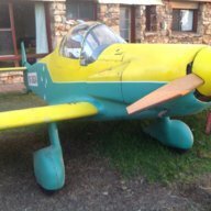
I have a VW 1600 adapted for aero use. About 60hp.
Lyle
-
Just came across your question, Jack. In case you haven't since found a solution, I used an internal probe of the type you mention, connected to a VDO gauge. The brass hose clamp it was locked onto is designed for a much larger pipe diameter so I made a copper collar to fit under the clamp to allow me to screw it tight on the small Jabiru pipe.
Lyle
-
Perhaps a forum on fitting recovery 'chutes into our many aircraft designs and incorporating them into checklists.
Lyle
-
Thanks fellas for the ideas. My stud pattern sure is 4" Dexter. Only a gorilla could get a 100mmm plate to fit. It's at least 2nd hand so warranty is probably long gone...
This arvo I checked the free play in the holes drilled thru prop and crush plates and found enough movement to allow me to tension the prop down with only 7mm of track variation. Perhaps I'm on the right track. I really only need c.0.8mm "slant" on each hole, which I could easily achieve with a chainsaw file. The prop will track true and blades will be close to equal length. The problem is then how to "lock" it there to prevent the sort of movement that Dexter warns about. Using epoxy to back-fill the holes seems the go, but is heat build up in the prop an issue?
Thanks for the method of checking pitch, Ralph. I am learning how multi-dimensional the job is! If the back of the prop is packed, eg. with a vinyl ester wedge, the prop bolts would have to bend slightly. Surely this would place worrying loads on these critical bolts? (I'm surprised that 1/4" bolts are employed on such a high-load area.)
Lyle
-
I am doing a static balance before I install my prop. I was told not to trust the centre hole (5/8") being exactly central but when I spin my prop on an axle thru this hole it tracks true, equal blade lengths and balanced.
When I mount the axle on a pair of crush plates (with 5/8" central holes) mounted either side of the prop the blades track 20mm apart, one blade is almost 2mm longer than the other and the balance is out. It looks like the machine that drilled the six 1/4" holes for the mounting bolts was not quite at 90°.
If this is the case I will have to use a file to elongate the front end of each hole 1.6mm towards the longer blade to correct the error, then fill the rest of each hole with epoxy filler.
I can't see an alternative; any suggestions?
-
VW Prop
Hello Mark
I have a much-loved Hoffman 27 X 59 prop which worked well in front of a VW rated at 42 hp.
If you can't locate a more suitable prop, this one could be trimmed to suit.
I believe that removing 1" off diameter is roughly equivalent to reducing the pitch by 2".
This means 1" off each end gets you a 27 X 57.
Old Koreelah
-
Now you're just being silly!
-
Avoiding glazing a J2.2
Thanks lads for the replies. All food for thought. (I started out with a VW motor which I liked because of its long-life/low-stressed power delivery. Perhaps I'm subconsciously trying to turn Rod Stiffs' little wonder into a lightweight VW.)
I sure plan to carefully run-in the engine, including using full power in climb.
Yenn, you're right about my D9 needing less revs than the Corby, but I need to to explore the following idea:
"... while there may be some glazing of the bores, the power required may be so little that it doesn't matter and fuel consumption would probably be 10 l/hr or less. I seem to be using 10 to 11 l/hr and cruising at above 100kts."
My original 1500 VW used about 6 l/hr doing circuits and short trips at c. 65kt, so I hope the Jab will use about 10 at 80-90kt.
-
Exactly, so if a detuned 2.2 Jab was working harder to pull me thru the air at the same speed, it should be loaded up and running hot enough to avoid glazing...
If that were true, would the lower compression put less train on the engine and improve longevity?
-
Thanks fellas for the replies. Having spent years streamlining the airframe to improve efficiency, I'm a little reluctant to fit a prop that wastes engine power.
The beast only needs about 60hp but all available engines were heavier than the Jabiru. The ideal would be a Jab 1600 if it were as reliable as the 2200. It occurs to me that the next best thing might be to detune the 2.2 so it delivers the 60 hp in a safe rev band. Perhaps it would also be under less stress and therefore last longer.
-
I fitted a jab 2.2 to my little special, mostly because of its light weight. If I cruise at 75% power I expect to be well over VNE, so a cruise at c.2500 is more likely.
All advice suggests at those revs I could glaze the bores. To prevent this I guess all I can do is vary the speed regularly, (This will certainly happen during the months of testing).
What is likely to result from shimming up the barrels to reduce compression ratio? The power loss wouldn't bother me, but would this reduce the chance of glazing, extend engine life and allow use of lower grade fuel?
-
Fuel Mizer manual
Thanks fellas, I guess I'm the bloke some of these messages are about. I received a manual from the Bushman and also downloaded one from the site you blokes found.
Looks like the variations in facia and brand name are superficial; both manuals are identical. I used both to test the Mizer unit today and it works well, calibrated accurately.
I need it because in flight it's quite hard to see fuel sloshing about in my see-thru wing tanks.
Thanks,
Old Koreelah
-
Surely you jest. Jabiru advise against running without the prop IN CAPITAL LETTERS so there must be a reason. Having a flywheel at the rear is OK but perhaps the engine is designed around having the additions flywheel effect of the prop at the front to reduce twisting loads on the crank. Jabiru put loads of design work into making it light, so I bet the engine relies on the prop for some of its flywheel effect. Lets be very careful with advice here.
Old Koreelah
-
I am interested in how you set up your third ignition system on the Jab.
Any picture available?
Old Koreelah
-
Fuel flow metre
Thanks for the link. Can you confirm if it reads below 10 litres per hour and what is the guage diameter?
Old Koreelah
-
shortening the Augmentor mixing section
If I follow all the guidelines above, the total assembly will be about 300mm too long. If I shorten the mixing section the cooling air and exhaust gas will not have sufficient time to mix, reducing the extractor effect. Perhaps I can install some twisting vanes in the mixing chamber to promote turbulence and get the two gas streams to mix in half the length. Any suggestions?
-
I sure have been augmented!
Thanks GraemeK for the info! It answers all the questions I hadn't been able to. Once I waded thru the ancient measurements (I unlearned imperial 30-odd years ago) it made lots of sense. It gives the relative sizes of exhaust and augmentor inlet, and the ideal shape of the augmentor.
My installation is tiny and simple by comparison, but the principles remain constant.
I had googled some of the text and found the original, then discovered that KB59 had also. Thanks fellas!
-
Thanks for the replies, people. My main aim is to achieve greater effficiency in drawing cooling air from the engine bay. If there is a muffler upstream of the outlet it should help reduce the noise to bearable levels. I'd be interested in details of that RV6.
Old Koreelah
-
Can anyone tell me why this apparently great design concept has disappeared from prop aircraft?
Surely in this era any extra efficiency would be embraced by designers. We need to squeeze all we can out of dwindling fuel.
I am designing an augmented exhaust to help suck cooling air out of my engine bay. I am planning to shape the exit for the cooling air like a velocity stack, with the exhaust pipe terminating at the mouth, relying on the bernouli principal to suck in cooling air.
There are several sources on the net, but none actually give advice on the intake area for the augmentor.
Can anyone assist?
Old Koreelah
-
The 1200 sounds exactly what I need. Does the quoted weight include gearbox, exhaust, radiator, etc? When is the first one due out?
Old Koreelah
-
FGI at Brookvale, NSW retain a chemical engineer who advised me that their vinyl ester (Derakane) is OK for fuels and has been tested with up to 95% ethanol.
WANTED: 65-100hp motor
in Engines and Props
Posted
My records say the basic engine is 68kg.
There are VW experts around who could squeeze more than 60hp out of a 1600, but that would probably require max revs with a smaller diameter prop, or a gearbox, hence more weight.
Regards, Lyle