

IBob
-
Posts
3,072 -
Joined
-
Last visited
-
Days Won
26
Content Type
Profiles
Forums
Gallery
Downloads
Blogs
Events
Store
Aircraft
Resources
Tutorials
Articles
Classifieds
Movies
Books
Community Map
Quizzes
Videos Directory
Posts posted by IBob
-
-
On 04/05/2024 at 5:19 PM, Area-51 said:
The only reliable performance procedure determinable to keep AC balanced was to fly on the left wing tank first until half reserve, then switch to right tank until half reserve then back to left, which will be almost full again after 10-15min........
That seems to suggest the return line is delivering at a very high rate.
I believe Skippydiesel did a fair bit of work recently with his return line orifice, and may be able to give us some rates from the various sizes he tried.
As for uneven feed, I am told all aircraft suffer from this to some degree. I have been able to reduce this on my Savannah by doctoring the angle of the ends of the tank breather pipes. But if I was building again I would look at some means of cross-porting the upper tanks, with a single breather, as Cessna do. Having said that, I have seen some odd fluidics in industrial settings, where separate flows are siamesed together: sometimes the flow from one input would take over entirely, excluding flow from the other, though admittedly this was usually in much higher flow situations than an aircraft fuel system. -
Assuming you want accurate weights (and in my view you'd be nuts not to) it starts with certifying or calibrating the scales. I checked mine with a range of certified test weights at a local industrial breadmaking business.
After that you can either raise and lower a wheel onto the scales (I used a small hydraulic jack) with the other two wheels packed up (I put a strop across to prevent the UC spreading).......
Or you can roll the aircraft onto the scales, which is not as simple as it sounds unless you have nice big pads for the other two wheels and a good sized lead-in pad for the scales. In theory at least this gets you away from the problem of the main UC spreading and putting side load on the scales. I believe this is how it is normally done.However you do it, you need to take multiple weighings and they should deliver very consistent results. If that is not happening, something is wrong with your setup.
-
 2
2
-
-
Further experiment and correction to above:
Weighed self on flat, then weighed again with scales flat but leaning shoulder on slippery wall: this is closer to the Savannah situation, where the weight is on the wheel, but there may also be side thrust as the UC spreads.In this situation, the scales over-weigh.
In both the above scenarios, the scales tolerated a small amount of tilt or lean without over or underweighing. How much probably depends on the design and construction of the particular set of scales.
-
Conducted minor experiment with digital scales:
Weighed self on the flat, then placed scales on rigid board, chocked up at one side so scales are no longer hortizontal, and weighed self again.
As the board is tilted up, the scales progressively underweigh.
So unless something is done to ensure no lateral load on the scales, the scales will underweigh.
Which could explain some of the unlikely low weights reported in other threads.In the case of the Savannah, if lifting and lowering the main UC wheels as I did for successive weighings, that means either preventing the UC from spreading when the wheel comes down, or arranging for the scales to move sideways, as Turboplanner did above. Or rolling on, provided that can be done smoothly.
-
There is a Statement of Compliance in the very front of my build manual, with various details including MTOW of 1320lb. But that form applies to my specific kit and serial number, it's not generic.
-
Lukeh, do you have the Pilot Operating Handbook that comes with the kit?
Mine is Rev 5, Revision 05.12.2014 and on Page 24/44 it states MTOW of 600Kg (while noting that local regulations may limit flights to lower value).
-
 1
1
-
-
Thanks Neil_S. It's been pointed out to me that a similar thread was run here some years ago, but it delivered a surprising scattering of results.
Having said that, weighing can have it's challenges, and I'm of the opinion that unless you can do multiple weighings with almost exactly the same result, something is wrong with the weighing process.
We do know that lowering main UC wheels onto scales doesn't work well, as the UC then spreads and the scales don't respond well to that sideways force. I got round that by putting a strop across the lower UC (then subtracting the strop weight when I got finished). That gave me excellent repeatability.Rolling on does sound like an excellent alternative, but in practice it needs fairly long and wide ramps and pads that will stay put as the aircraft is manhandled. And again the aircraft has to be moved without inducing any UC spread or flex.
-
Some headscratching locally over Savannah S empty (no fuel, brand new ) weights, as taken at the initial Weight & Balance.
My S, with standard steam gauges, long range tanks, extended baggage, carpet, adjustable seats and Condor tires (next size up from standard) came in at 314.8Kilos
I'd be interested to know numbers from other builders/owners.
Thanks!
-
1
-
-
Hi Kogg, nice looking machine.
When ICP altered their design by removing the slats and adding VGs, they also altered the profile of the leading edge of the wing. However, it's not clear what difference the change of wing profile made.
Your best source of information for your aircraft would be JG, who pioneered the slats-to-Vgs conversion on that model and conducted a great deal of testing. He flies the same aircraft as you, with slats removed and VGs added, and I don't think he changed his wing. His website is Stolspeed and is a goldmine of information. Suggest you contact him, see if he is open to a conversation:I'm a bit puzzled that you say 'im buffeting and beginning to stall power off with no flaps at 60 mph.' I fly a Savannah S, the POH gives a flaps up stall speed of 30 to 35 kts depending on loading, and I know it cruises quite happily at 45kts.
I note you are flying pretty much at Max All Up Weight and it could be interesting to know what your Weight and Balance is.
-
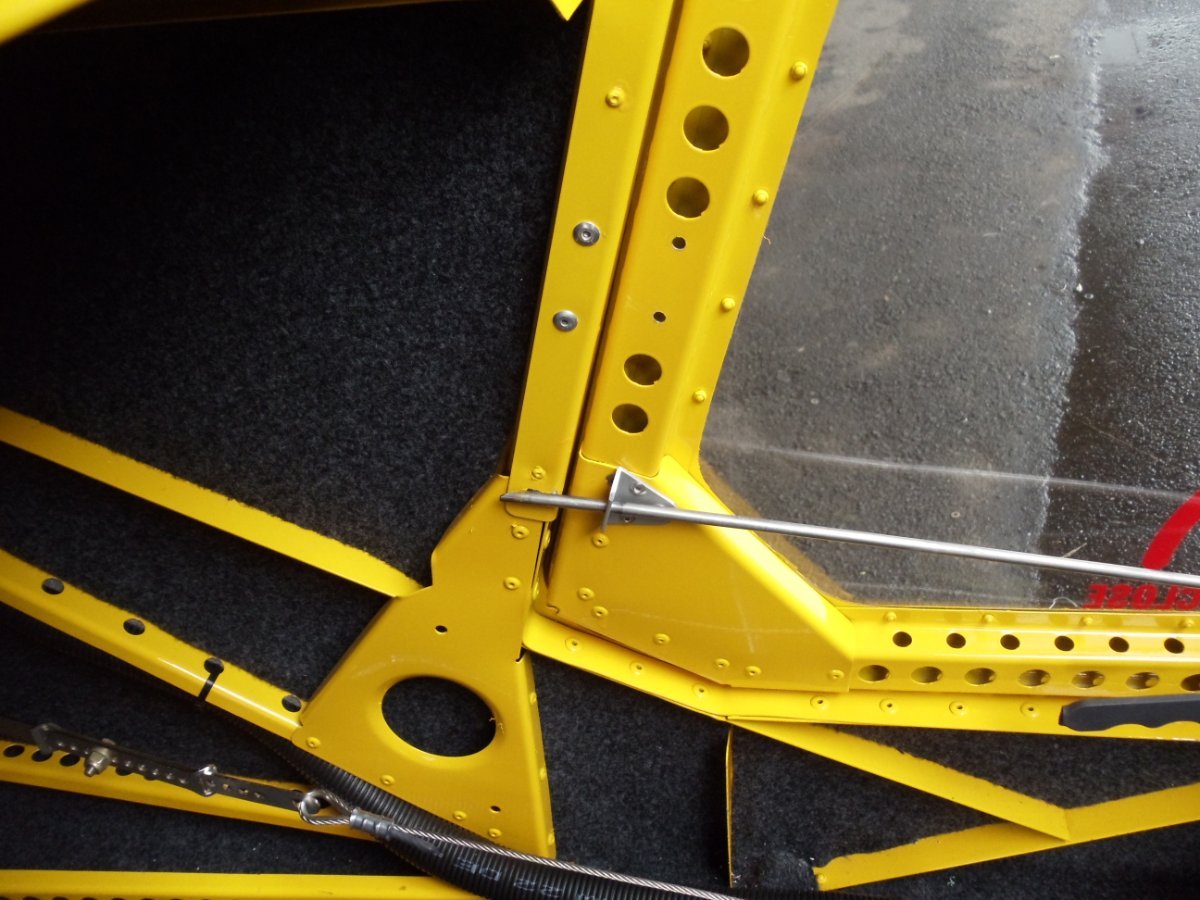
Gary, I don't have a pic of mine, but here is a detail from the pics the then agent (since retired) sent me.
I think he made the closer kits locally. He was responsible for a number of innovations, and also completed many kit builds.
You can see how the rod is tapered on the outboard side at the end, both rods are like that. As mentioned, I also found it helpful to bend the very tip of the rod inboard a bit.
I also looked at his pics to try and see if they also used the standard door front latch. It looks as though they didn't, but certainly the over-centre action of that latch will pull the front centre of the door in snug.
-
Gary Nelson, neat job of the door closers!
On mine, the rear rod goes into a hole in the fuselage frame, outboard of the extruded angle there. The hole is reinforced by a little SS plate, held by 2 rivnuts, with slotted holes to allow some adjustment.
And the rod ends are not points, but shaved off to a point at a gradual angle on the outboard side so that they pull the door in as the rods move to the closed position. I found the door closed more readily if I bent the tips so as to give an easier lead-in. -
That looks great, Garry Nelson, and shows much of the necessary detail.
Would need to be modified for the S, where the bottom edge of the door is not in one plane as it is in the VG in the video.Aside from that it looks like 'just' fabricating an al tube door frame to match the lower doorframe, then attaching polycarbonate with some sort of outer flange. Hinge and latch.
I note he did a nice job of curving the upper frame member out wards (pretty much as it is in the standard S door, to give a bit more elbow room).
I see in the flying footage he also has a polycarbonate deflector at the front of the upper door space.As for the standard S door:
It's not easy to remove without risk of knocking your paintwork around.
And I have 3-point door closers, sourced with my kit from Australia, though I do not know if the agent there still makes them.
-
I bet Mum was really pleased that going on holiday didn't interfere with her cooking.......though if the TV fell in the sink it probably would have......(
-
 2
2
-
-
On 13/04/2024 at 12:17 AM, Area-51 said:
Several ways to go; retain whole door frame and cut off upper plexiglass section; or have sub frame for top half plexiglass that hinges down from midpoint; or delete upper plexiglass and fit adjustable deflectors at forward down channel of door frame, like on pre 60's sportscars/roadster windshields. Deflectors only need to be about 4" long to be effective
Area 51, a couple of things to take into account regarding the standard doors:
1. They are bat-wing in operation.2. They are not a rigid frame with the polycarbonate attached. They are upper and lower windows, with their joining point shaped and anchored together in such a way as to produce a slightly bubble shape, with a light frame around the whole. I am not confidant that the upper section or the upper polycarbonate could be removed without greatly weakening and probably deforming the remaining door. But I may be wrong......
-
 1
1
-
-
The Savannah S POH says it may be flown with one or both doors off. That side-slip should be avoided if only one door off. And that drag will be increased, particularly at high A of A.
-
1
-
1
-
-
That's a really enjoyable interview......)
-
2
-
-
1 hour ago, Marty_d said:
But how many times did a giant woman wrap herself around your plane?
Marty, I'd settle for once......)
-
1
-
3
-
-
I wonder if the problem could be inadequate strength/bracing in the float?
We once had a f/glass canadian canoe. Heading for home in failing weather after a week on a big lake, I accepted a tow from a power boat. While there was little in the canoe (just me), when the canoe got onto the wave from the boat, the bottom went flat then dinged in sharply. And while it didn't break or tear, as I recall there were stress marks where this may have happened before. -
Nice looking job, Marty!
Another option is to have the the LE sitting in a sling, webbing or I used a strip of carpet, attached at a centre high point of the frame then passing down and under the LE, with the other end attached at a raised point over where your casters are. So the wing is sitting in a pair of slings, which conform to the shape of the LE, and are not resting on anything hard or solid.
I copied mine from a pic I saw somewhere, passed it to another builder who has beefed it up and added wheels, it has now passed to a third builder...........)-
1
-
-
Depends what you are viewing on Flying Dog:
On my laptop/PC it's a blue Following button at the top RH corner of the thread. Click on that and you can unfollow the thread. -
Danny, you may want to check the current output of that USB port: I have seen an aircraft equipped with them initially, but subsequently replaced with good quality conventional USB charging ports. I can only assume either that the output was inadequate for whatever they were driving (tablet?), or that they were electrically noisy.
-
 1
1
-
1
-
-
BTW, there was early first person footage of parachuting into trees. Probably deliberately, as it would have have taken some effort back then to mount the camera gear.
This was round canopy stuff, and shortly after entering the trees it looked like the jumper fell very sharply.
I think what can happen is that if the jumper/payload/aircraft momentarily snags in parts of the tree, the canopy above continues descending or deflating. Then when the j/p/a unsnags and falls it is now no longer supported by the canopy, so can fall at a much higher rate........
-
1
-
2
-
-
Well, that's a relief........was trying to figure how to get them to take the net down in time............)
-
3
-
-
Suggest you avoid smoking in the dunny, though???
-
3
-
Pipistrel on Fuel Vaporisation
in Aircraft General Discussion
Posted
FlyBoy certainly friction losses may be a significant element, though they are far more noticeable with higher flow rates.
I believe the difference of pressure in separately vented tanks to be far more relevant:
Eg: The fall from my fuel tanks to my fuel selector manifold is approx 250mm (the selector is on the RH baggage wall, where I can see it). Add approx 200mm for full tanks = 450mm which gives a fuel pressure at that point of just 0.49PSI
So very small differences in upper tank pressure due to slightly different venting, prop swirl etc can result in proportionally large differences in fuel pressure from L and R. And that will only get worse as tank levels fall.
Aircraft with floor mounted fuel selectors are marginally better off. In mine that would double the pressure at the selector, but certainly not enough to minimise the effects of unbalanced venting.