Bodie
-
Posts
32 -
Joined
-
Last visited
Content Type
Profiles
Forums
Gallery
Downloads
Blogs
Events
Store
Aircraft
Resources
Tutorials
Articles
Classifieds
Movies
Books
Community Map
Quizzes
Videos Directory
Everything posted by Bodie
-
Here are some of the rivits I ordered from Aircraft Spruce to replace some of the rivets that needed to be drilled out 🤐... I was told to get these by the North American distributor as a match for the A3 - A5's. I also needed a few with different length shanks, and a few countersunk ones but those were kind of self-apparent at the time.... hope this helps.... 1661-0512 DOME AVEX RIVET (PACK OF 50) Part #: 04-01949-50 Mfr Part #: 79093-50 $5.000 / EA AVEX RIVET # 1601-0410 Part #: 1601-0410 Mfr Part #: 1601-041 $0.090 / PC-10.0% Net $0.081 1601-0414 AVEX RIVETS Part #: 1601-0414 Mfr Part #: 1601-0414 $0.080 / PC-10.0% Net $0.072
-
I needed help with the extensions. One guy on the outside holding and pushing and one guy on the inside holding, adding clecos, and drilling rivet holes. Less than ideal anyway. I don't think I could have done it alone. And yes, the roof was / is a puzzlement for sure. Best thing to keep in mind is that some things are structural and some things are cosmetic. I didn't mess with the structural as I'm not a designer / test pilot. As far as cosmetics go, with the "experimental / amateur built" designation feel free to exercise a bit of your own ingenuity. At times, I wondered if the Italians engaged the Chinese to translate the manual into English. Truth be told though, after reading the troublesome parts (including the pages before and after) most of it makes sense. This forum was the best help for all things not understood, however.
-
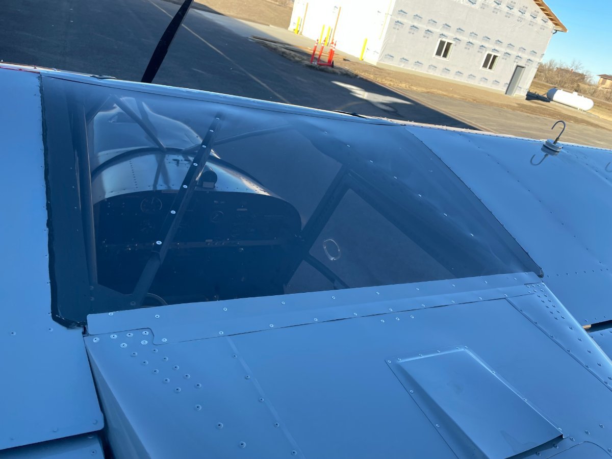
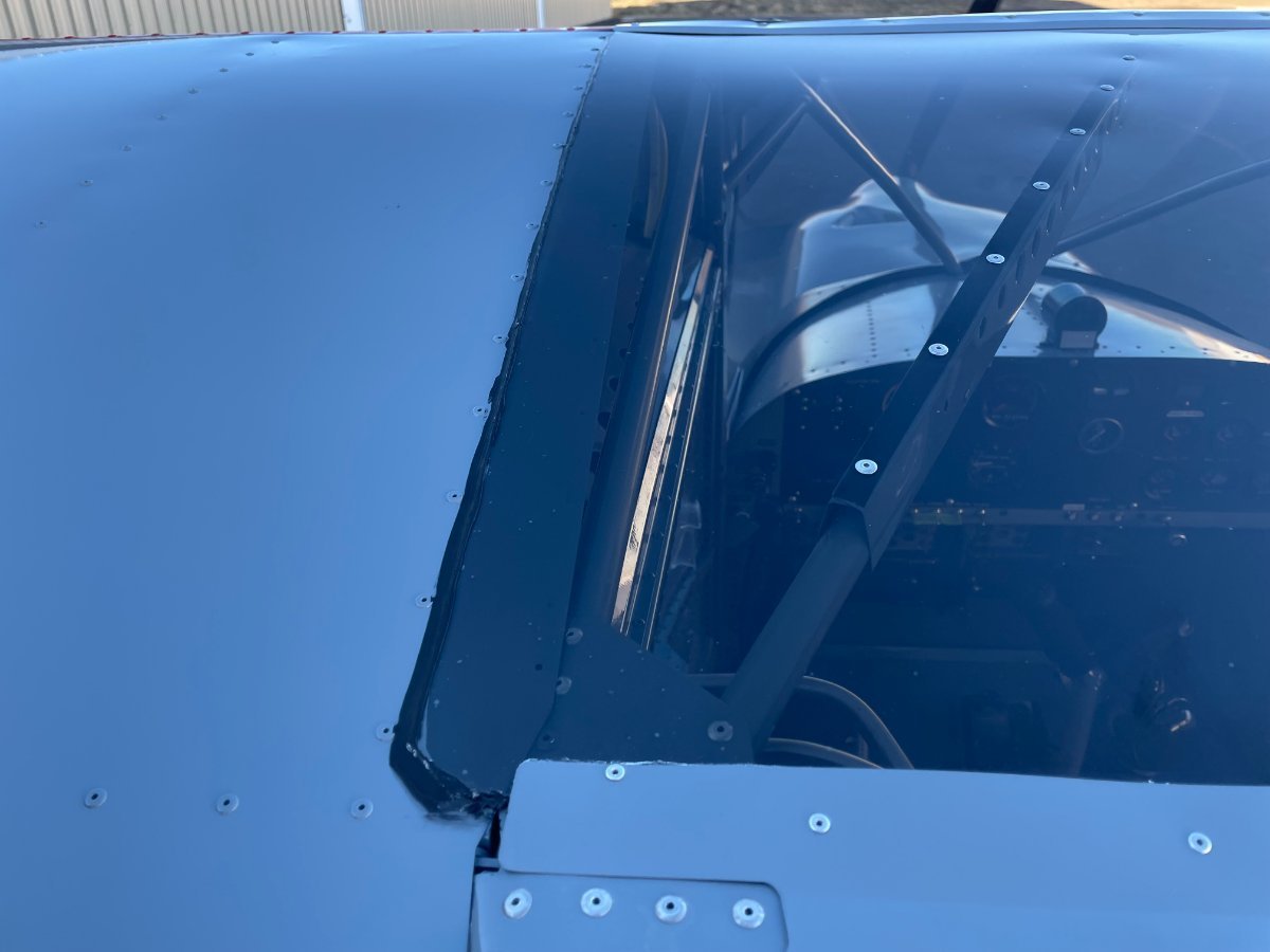
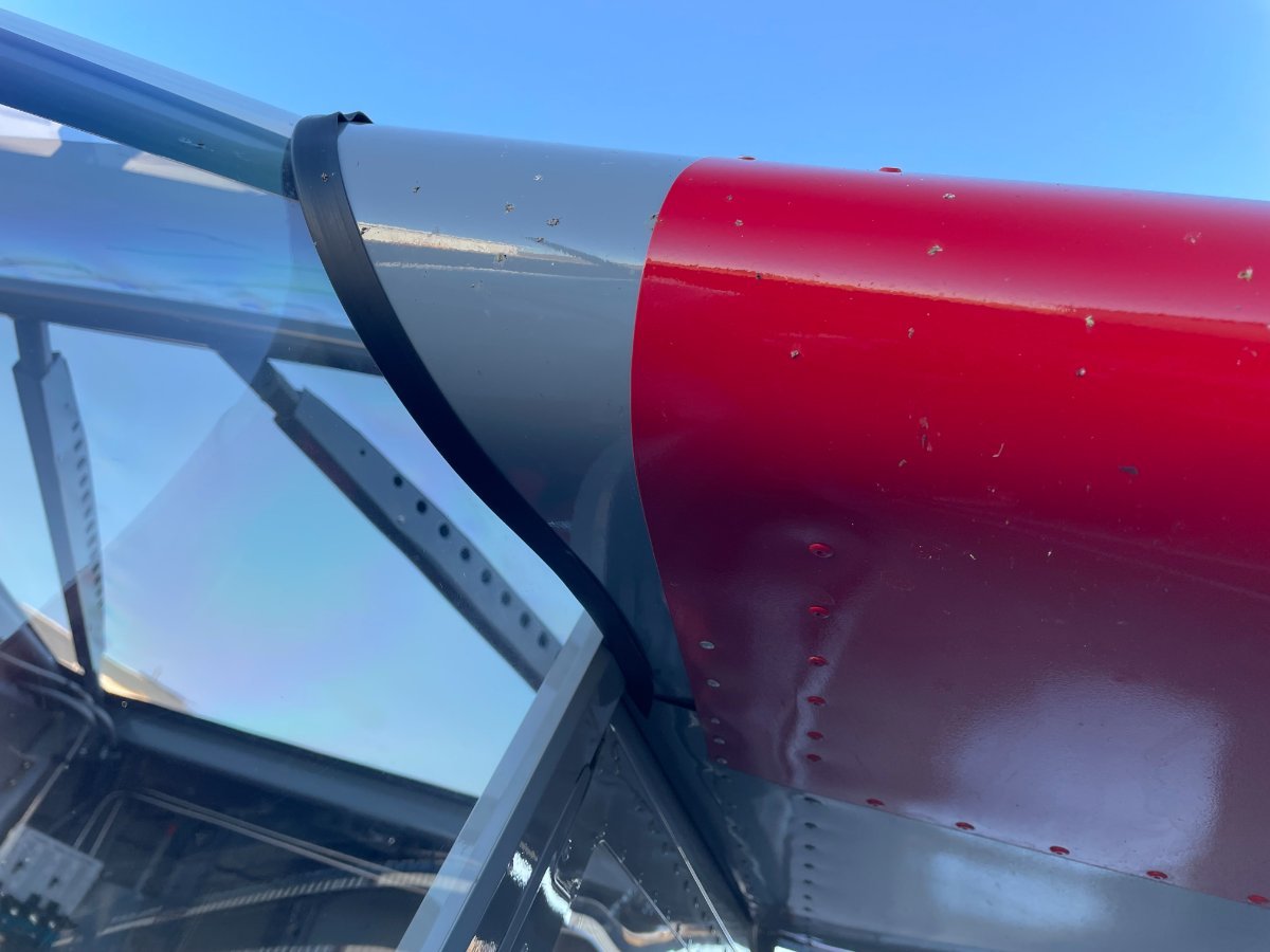
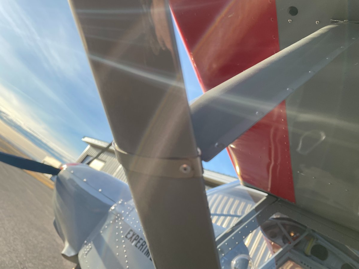
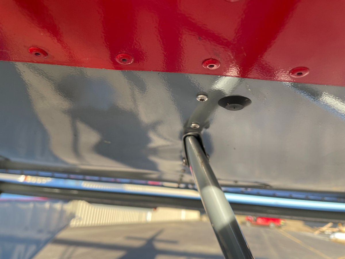
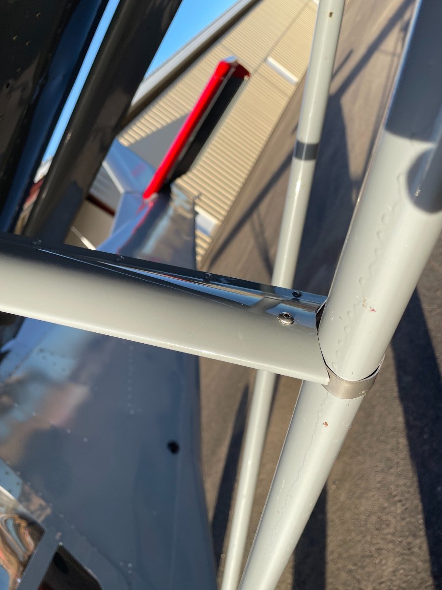
Don't know if you got this all sorted or not, but I snapped a few pics of my install. I didn't rivet the lexan on the roof panel. Instead I used urethane automotive glass adhesive on the edge. The rest of the pieces fit with quite a bit of fiddling around. One side of the wing leading edge extensions turned out better than the other, but that's the way the world works sometimes!

-
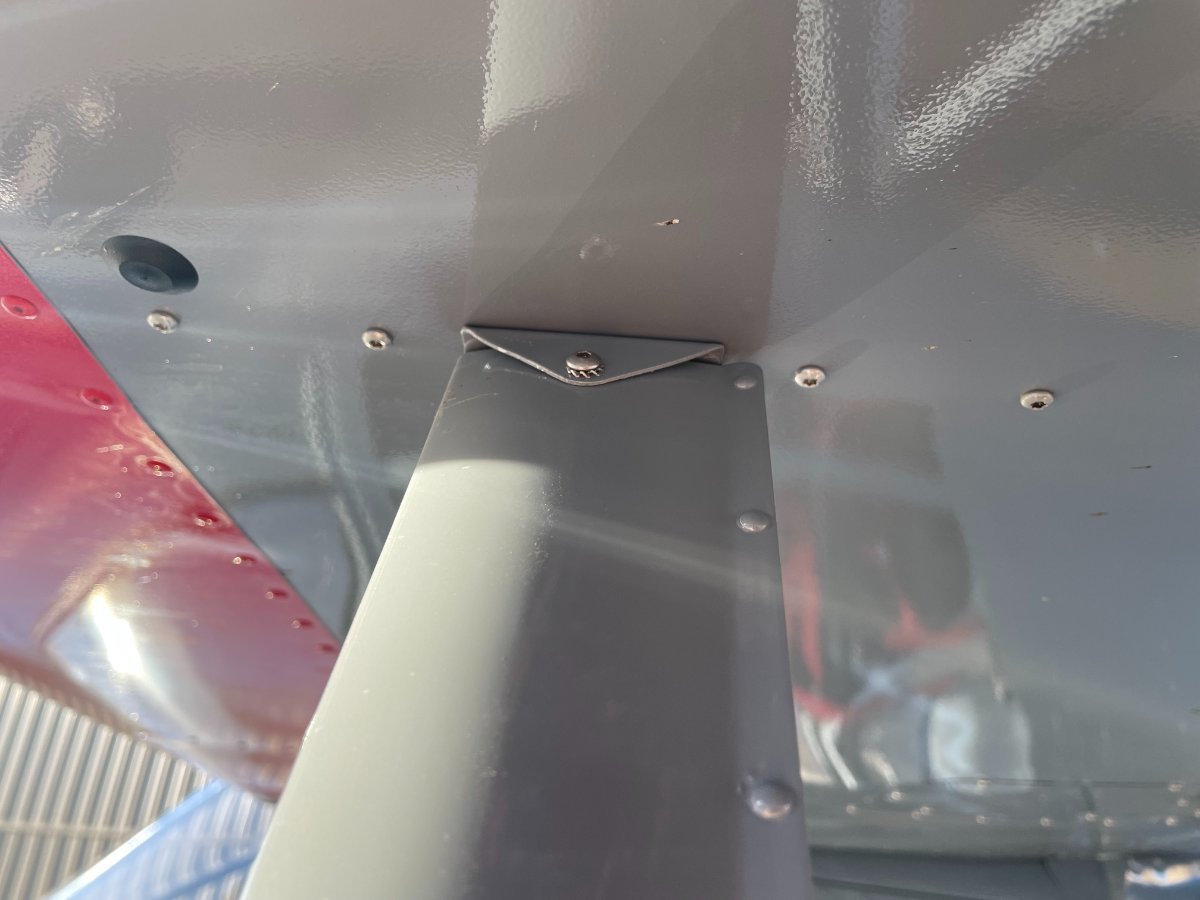
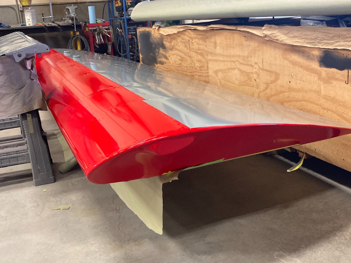
Hey Bryan. I was able to get some pics for you. I hope they help. Please ignore the paint runs in the third pic. Don't paint outdoors in a cold November in Montana! -steve
-
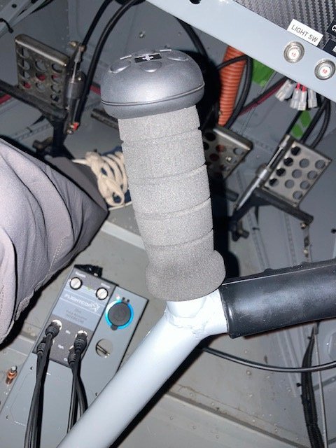
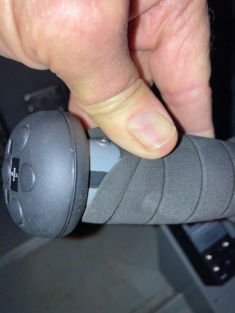
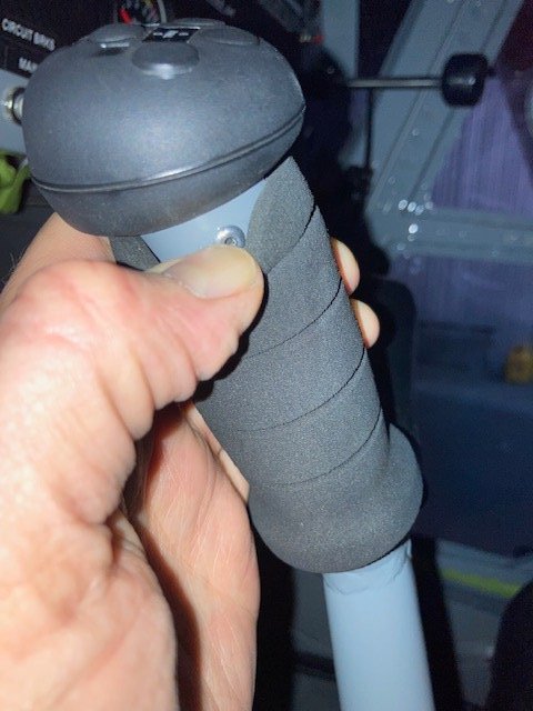
I looked at my Savannah to remember what I ended up doing, and here are some pics. Not sure if this explains well enough, but I made a hacksaw cut appx 70-75% around the end of the yoke, then I resized the pipe. I can't remember if the y yoke pipe is smaller or larger than the plastic end of the grip that inserts into the y yoke (see pdf). I then fit the G205 head into the yoke and rivited it in on opposite sides. You have to be mindful of the rivits ends so that they don't interfere with any of the electronic parts inside of the plastic. The foam grip went on before this with soap and water, then it was gently worked up. It fits well. I have to find another foam grip so that I can junk out the tricycle handle bar grip on the other side. Hope this helps. -steve 2023-04-05 (1).pdf
-
The stock rubber grip is something I remember from 55 years ago on my tricycle! I chucked it and used the ray allen g205 that I got from aircraft spruce. I had to do a slight bit of modification but I can’t remember exactly what I did. I can take a look next time I’m in the hangar. It wasn’t hard to get to fit up. -steve
-
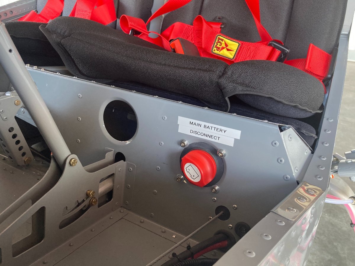
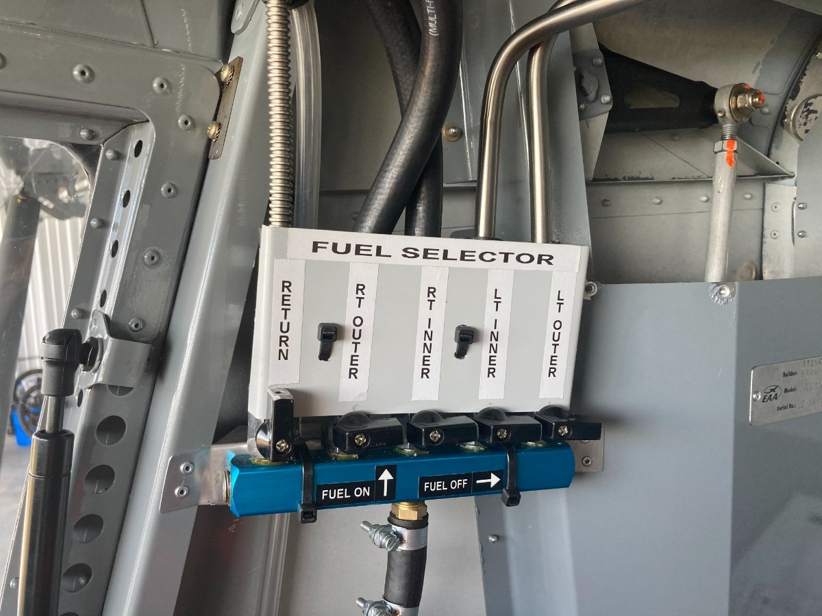
I thought I'd throw a couple of pics up after taking to some of the folks via PM. I copied the Fuel Selector and Return header as well as a variation of the master battery disconnect from folks on this site (all sourced on Amazon. I didn't do the improved flap handle yet. In the USA we can get a Repairman Certificate if we are the original builder of the kit. I just got that today too, so I can do a yearly inspection in lieu of paying someone for an Annual. -steve
-
Hi All! I just wanted to shout out a big Thank You to all the folks on this forum. If it wasn't for folks from all over the world, especially Australia and New Zealand my Savannah S project wouldn't have been completed as soon or as easy as it was. In particular Kyle Communications and iBob's threads had a lot of tips and tricks, and the back and forth with the other folks clarified most situations I came up against. Whether it was wiring, fuel tanks, manual clarifications, etc the problems were all sorted out, many times by searching through other threads. I was building my plane for way too long, got interrupted by life way too many times but persevered. When I hit the point where I didn't know if I would ever finish I read somewhere (not sure if it was here or not) that I just needed to do something every day. Anyway, I started the project in October of 2015, and I witnessed flight today. I still need to get my license, but at least I have my plane! It was great to finally see some air underneath the tires, and someday soon I will fly her myself! Thanks again! -steve IMG_4128.MOV IMG_4129.MOV IMG_4131.MOV IMG_4132.MOV
-
Thanks guys! Here's my best guess. The 50 amp fuse and wires are a part that is bought from another supplier, hence Marty_d's 701 and the Savannah are the same. I re-read Mark Kyle's response and I will use one wire for the resistor and clip the other then terminate it in heat shrink!
-
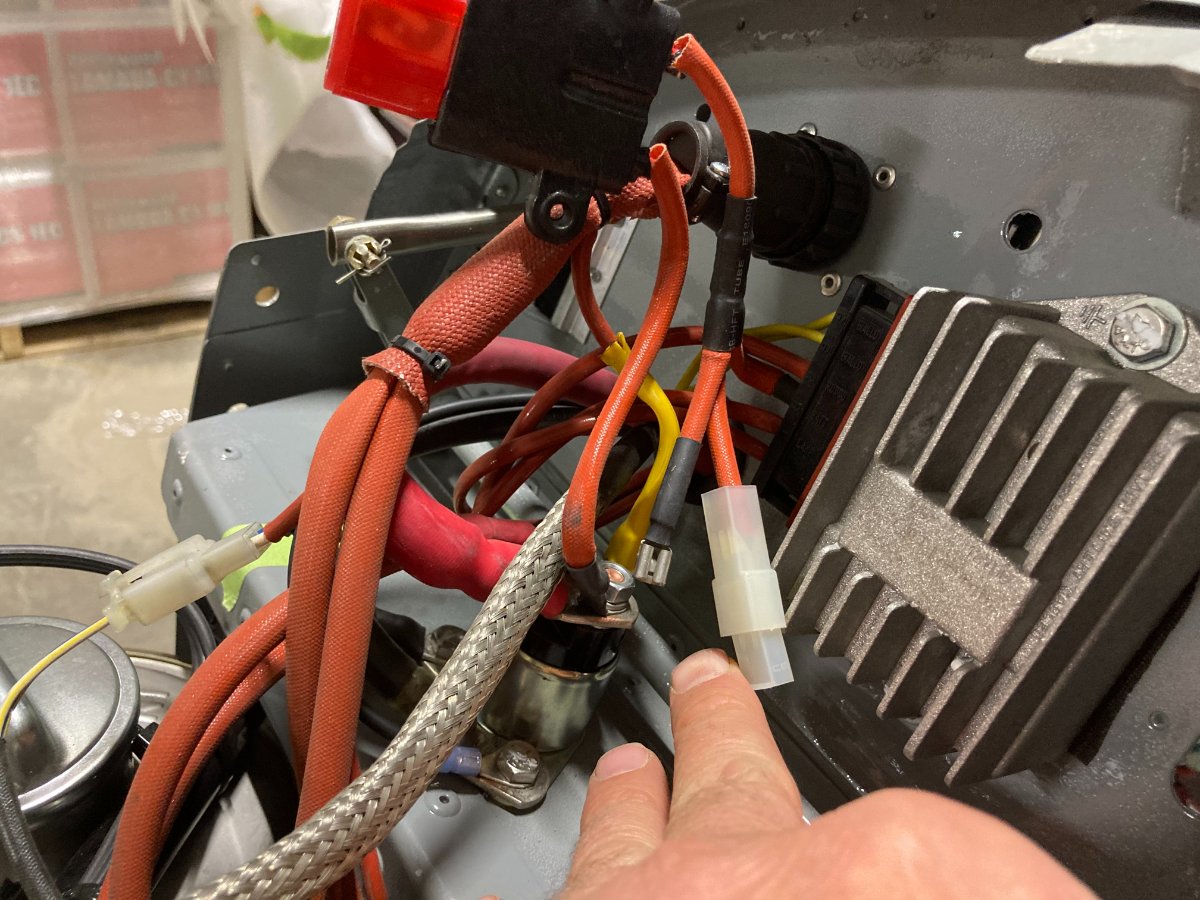
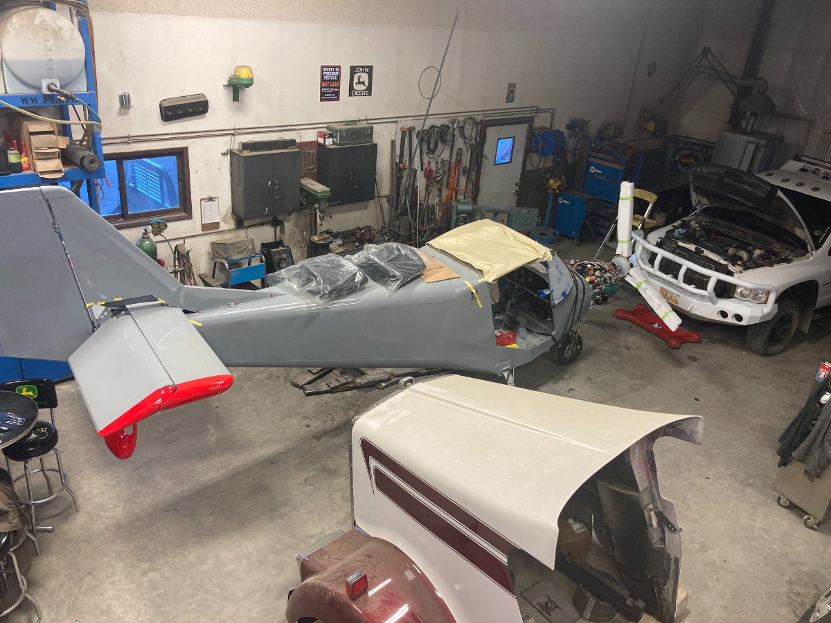
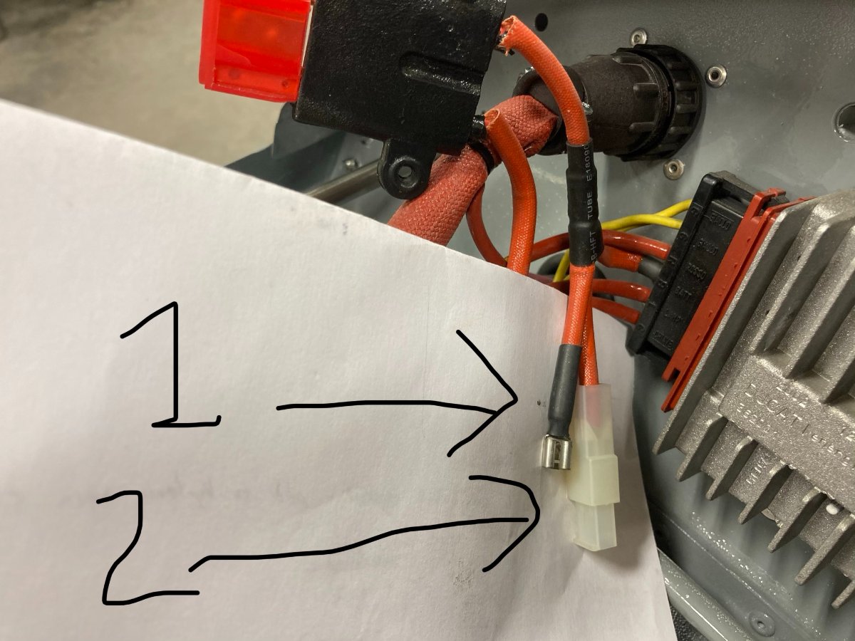
Thanks guys. I'm tracking what you're saying Ibob. I have the one end of the 50 amp fuse connected to the battery wire on the solenoid. I stuck the white paper in for a clearer picture. So then the other side of the 50 amp fuse goes to the battery terminal of the voltage regulator. That's good so far. The picture you sent of Marty_d's is the same as my dilemma, where are the other two wires supposed to go? And namadpete, I too would have expected the schematic to explain things, but apparently there are just things that the Italians like to leave to chance in their manual. They have a great schematic of the cabin side, but no schematic of the other side of the firewall.... so are you suggesting that the 22mF capacitor should be connected to one of the spare wires? I've attached another pic with the detail the first pic lacked. One side of the 50 amp fuse connects to battery terminal of starter solenoid. On the other side of the 50 amp fuse one leg goes to the battery terminal of the voltage regulator, and the other two have no obvious place to go..... Also, not wanting to encourage thread drift by any means since I would like the electrical issue solved 😉, have attached a few current pics of my 6 year project!
-
Hi all. I got what I think should be a simple question, but can't find a logical solution. After the 50 amp fuse in the engine compartment, there are three wires. One goes to the "Bat" on the regulator. The other two wires are the ones that I don't k now where they connect to. Can someone tell me where item #1 and item #2 are supposed to connect to? Thanks! -steve
-
Thanks for the info. From previous posts on the savannah forum I read I had already done that, although only on the left seat where the fuel, electric, flap control, etc go. I didn't think there was much need to get under the right seat except I see a few folks place electric fuel pumps on that side.
-
Hi Perry. Thanks so much. The pics are perfect, and you have a nice tidy setup. Appreciate the commentary about keeping clearances in mind. -steve
-
Thanks IBob. So it looks like you ran both brake lines into the cabin on the left hand side? Did you go under the seats through the tunnel? -steve
-
Hi folks. Finally seeing some progress now that I am in the 90% completed and only have 90% to go category. I was wondering if someone could post a pic of the completed dual brake setup showing the routing of the brake lines and how they loop from the master cylinders to the slave cylinders. I'm just not exactly sure how much excess line to leave in the loop for clearance, etc. Once again, the instructions have been a bit less than stellar.... Any advice would be welcome. Also thanks again for all the great posts. This site has been a wealth of information. -steve
- 12 replies
-
- 1
-

-
- savannah
- savannah s
- (and 1 more)
-
Thanks again, gentlemen! The aluminum is in the scrap bin! IBob, I'm a bit confused here being on the other side of the world and the other side of the equator. Did you mean 1/4"BSP? Which I would guess would equate to 1/4" NPT... I like the looks of that setup and will do the same. I have 4 tanks and only plan on using the two inboard. I bought stainless steel tubing and ran that through the wing to the cabin. Except for the short hose connecting the tank hose barb to the tubing, I have no rubber hose running through the wing ribs . I figured it would be easy to replace a short than the whole piece.
-
Thanks guys! Kyle Communications, what size cables are you using in your Sav? Also, I'm getting to where I'm going to plumb the fuel header tanks, and I like your 4 valve setup. Was that a 1/4" npt block you used? With 1/4" stubby ball valves? I looked through the other posts and couldn't seem to find the size. The Sav kit does a great job of switching between metric and sae (kind of like our John Deere farm equipment!
-
My S kit has an aluminum positive cable. Are the older kits copper or aluminum? Easy enough to cross reference the carrying capacity I guess.
-
Thanks IBob and Jabiru7252. I noticed on the Savannah S I was learning in that the carb heat was slow in recording change during run up. That makes sense. Also, I hear what you're saying on not relying on the airframe as the ground. On all our ag equipment the most common cause of electronic problems short of failure are related to insufficient or corroded grounds. What gage wire do folks use for the "additional" ground?
-
Great IBob! That all makes absolute perfect sense. If only the manual were so! I'm getting to the point on this build that I can see the end. I don't know what I would do if it weren't for this site and all the help. Right now I'm waiting for some parts that were missing from the kit, a couple that I inadvertently buggered up, and some parts from Aircraft Spruce. I need some decent weather for my "Big Sky Shop Paint Booth" (relatively warm, bug free day).
-
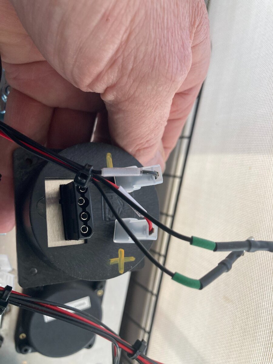
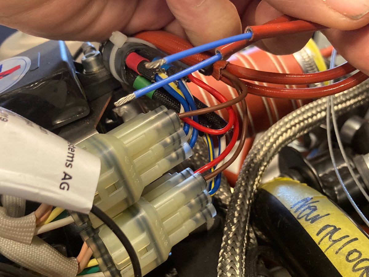
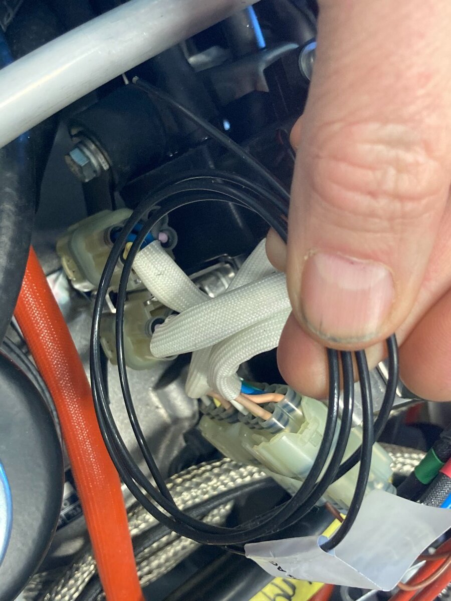
Hello fellow Savannah Builders, I have 4 wiring questions. After scouring the manuals (both Rotax and Savannah) and the forum I can't seem to find the answer. 1) The first pic is the backside of the airbox and outside air temp guage. Can someone tell me to which points the two signal wires attach? 2&3) The second pic is the wiring near the ECU. I think I have the brown wires correct? and, where do the two blue wire go? 4) There is a black wire coiled up near the ECU. Where does it go? Thanks guys. -steve
-
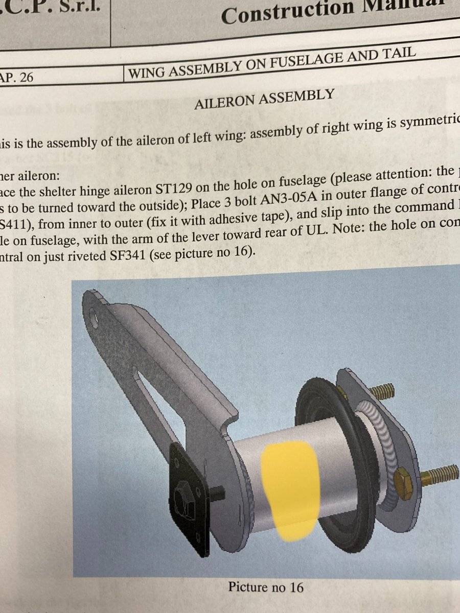
Thanks for your patience. I get what your saying now. The bolts is just for initial alignment, and the bracket is really just an extension of the aileron rather than the aileron being an extension of the bracket. I was thinking about it bass-ackwards! -steve
-
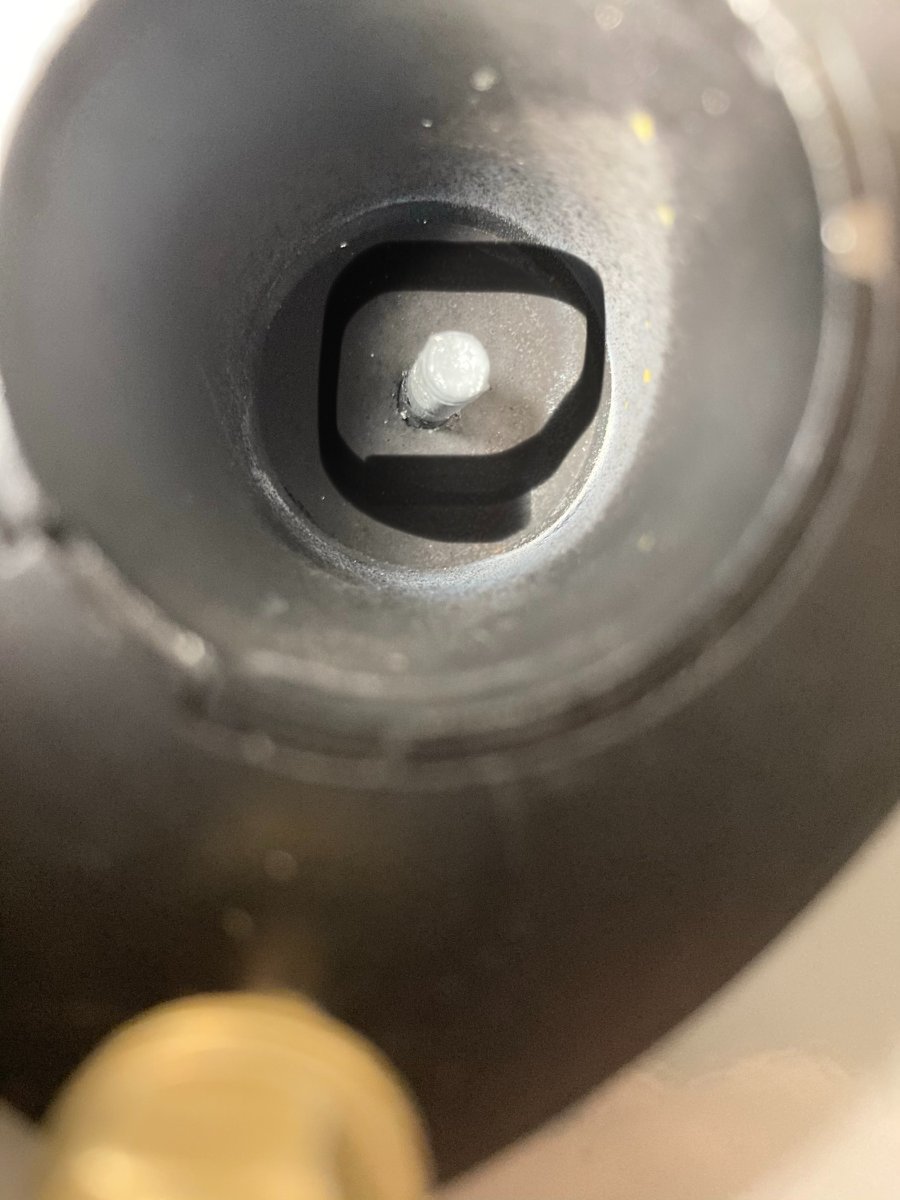
I've been giving this aileron pivot a bit of thought (maybe to the point of over-analyzing it!) and I just don't like a metal edge on a bolt. I'm thinking of machining a round piece of plastic 15mm or so in depth and pressing it into the hole and drilling it to the dimension of the bolt for more bearing surface. Has anyone looked at one of these with some hours on it, and is the wear acceptable? I'm wondering what Kyle Communications saw on his re-build... Thoughts?
-
Thank you, I was beginning to lose confidence in my self! Here I am with fuse built, tail feathers built, wings built, engine installed, and losing faith that I've done anything right! It seems that would be a nice bit of info to have, and if it is in the manual I surely couldn't find it..... Thanks again. -steve
-
Hi again folks. First off, thanks to you all for bearing with me. I appreciate all the helpful folks on this forum. I can't seem to decipher the manual, the parts list or find that the question has been previously raised on this forum. How is the bracket held on the the protruding bolt inside this tube? I also notice that the bolt is drilled for a cotter pin. Thanks all! -steve