rgmwa Posted April 21, 2014 Share Posted April 21, 2014 I'll give you an example - what dictated the shark-like shape of the Me 262 fuselage? Was it the need to find somewhere to put the wheels when retracted? rgmwa Link to comment Share on other sites More sharing options...
Bob Llewellyn Posted April 21, 2014 Share Posted April 21, 2014 Depressing picture of just how inefficient the whole thing is when you analyse what you are up against. Structural reality is that total payload will never be better than empty weight Total load inc fuel will be about 40% of AUW, generally .. You don't have to build a truck to take 6 times it's normal weight. Nev True - the Transavia Airtruk and Pawnee Brave 400 and Fletcher FU-24-400 all have a payload greater than 50% of the takeoff weight. So now we know what efficient aeroplanes look like! Link to comment Share on other sites More sharing options...
djpacro Posted April 21, 2014 Share Posted April 21, 2014 ......It is my understanding that the Joint Strike Fighter FEM teams entered an intractible dispute, and they had to build two extra prototypes to resolve the FEM disgreements (back about 2006/7)... First I have heard about it but perhaps it was on the UK side? We had 200 or so people working on design and structural analysis of the JSF in Australia and I'd think I would've heard about something like that. The project certainly went overboard on FEM and I agree that many people don't know enough to question the output. ... Hoerner himself states that there is no credible method for predicting laminar to turbulent transition around a 3-D shape, and the physics haven't changed... He would've said that a very long time ago. Gee, that was even before my time and I can remember being excited when the mainframe computer expanded to 34 Kb. Physics hasn't changed but the capability to solve equations representative of the physics certainly has. Link to comment Share on other sites More sharing options...
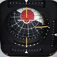
Bob Llewellyn Posted April 21, 2014 Share Posted April 21, 2014 Following on from their CATIA CAD package, French Company Dassault Systemes produced Solidworks specifically for the Aerospace Industry although it was quickly adopted into other major branches of manufacturing. Solidworks incorporates very sophisticated computational fluid dynamics (CFD) and finite element analysis (FEA) capabilities. Commonly referred to as 'simulation and visualisation' they allow you to 'see' the effects of fluid flow and application of stress over and on the surfaces and members of a structure. The software can also generate a complete stress analysis for the individual members and the entire structure.There are other packages with similar capabilites, Autodesk's Inventor has add-ons for both. As for which to choose, a lot depends on which CAD platform(s) you are most familiar with. AutoCAD people will tell you that Inventor is the only way to go, realists with a handle on future trends are likely to start with, or learn, Solidworks. The essential difference is how the software goes about defining the model, AutoCAD is a geometric system and Solidworks is parametric although AutoCAD (and Inventor) now has a parametric design constraint tool. For the most part you don't need to know how the model is defined until you get into very complex solutions. Parametrics comes into its own when you want to change something you did near the beginning of the model and you want all associated members/items to change in a similar proportion, to remain 'linked' with the first item, for example. Most former NASA and Boeing engineers seem to favour Rhinoceros (Rhino), a NURBS-based geometric modelling package and it has FEA and a Grasshopper Components plug-in for CFD and files can be converted to Solidworks format to use those features if required. Many other engineering softwares will do the engineering calcs for you too - Tekla Structures (formerly X steel), Graitec Advance Steel etc, they are very expensive but you may know someone who has a seat. The main thing to keep in mind is that although (most) models from one format can be imported and exported from one package to another they lose their interactivity and so will not be 'live' within that other package, they will just be a simple solid or surface. In that case migrating from parametric to geometric is not so much of a problem because the solid can reasonably easily be rebuilt in AutoCAD for example, but if you take a geometrically developed solid into a parametric package it's just a reference solid and rebuilding it to make it 'live' (interactive with other parts of the model), means starting again. How much of a hurry are you in? For those who are competent in any 3D CAD package you can follow a tutorial and be able to do the basics in Solidworks in a couple of weeks but will only be slightly proficient in about three months and competent in twelve months. After a decade you'll still be learning - I'm talking full-time here ... Many people start their CAD work at school or college with AutoCAD and therefore the learning curve will be much quicker for them in Autodesk's Inventor but you still won't be able to do the clever stuff for a long while. The other consideration is cost. If you get yourself registered for something in the Engineering field at TAFE or Uni, for example, you can download limited functionality student versions of most of them, which stay activated for three years or so, and the extent of functionality is sufficient for most private purposes, quite enough to design an LSA for example. Once you go to the professional level you'll have spent enough on software to buy a brand new LSA ... The pro versions basic costs (excl add-ons and in USD) - Solidworks about $12K, Inventor $8-12K depending on the re-seller and it includes AutoCAD, Rhino/flamingo is the cheapest and best value for beginners at about $1K plus a few hundred for the add-ons, Tekla is about $35K and Advance is about $10-15K. If your only interest is to experiment a bit and see what difference a few changes make to the performance of a basic aircraft form you could have a play around with X-plane. It's quite a different concept, you download the (free) software and produce an aircraft model of your own design - or choose from thousands of online models - and change the basic model by dragging 'handles' until you have what you want. Then you define the engine power and type(s) and various other parameters and go and fly the plane in the simulator. Then go back into the model, change it and fly it again and compare the difference. The thing to remember with X-plane is that although the software makes a very nice rendered image of your plane for you to fly, the rendered image isn't fully representative of the plane you fly in the simulator because you are flying the parameters you input, not the model, so if you don't define the flaps accurately the performance won't reflect the flaps you may think you have, if you get me. Also, disregard a lot of what X-plane indicates about stall characteristics, it doesn't cope well with anything other than simple stall behaviour. Disclaimer - I've only played a little with X-plane so others know much more about it than I do, but some pretty experienced and successful designers speak well of it (for specific purposes) and use it as a matter of course to test their new design progress. Below are some images, the first three are examples of CAD FEA, the first showing the stress on a wheel as it would be when loaded with the weight of a car, stress on operating turbine wheels, a loaded chassis showing the point of greatest deflection. The rest are CAD CFD showing pressure distributions, the last one is probably something close to what you are looking for, and demonstrates why modern airliners have the bulge below the wing centre-section and have been able to reduce the size of the fillets as a result. Co-incidentally a very handy space for the gear and systems stowage as well - note how evenly spaced are the isobars. [ATTACH]28023[/ATTACH] [ATTACH]28024[/ATTACH] [ATTACH]28025[/ATTACH] [ATTACH]28026[/ATTACH] [ATTACH]28027[/ATTACH] [ATTACH]28028[/ATTACH] [ATTACH]28031[/ATTACH] [ATTACH]28029[/ATTACH][ATTACH]28030[/ATTACH] The bulge below the centre section was developed from theory in the 1950s, as discussed in Stinton's Anatomy of the Aeroplane (the other book); if you look, you will see that the airfoil is also inverted at the root. Compressibility, it's all about compressibility, and pre-dates CAD FEM by a while. Link to comment Share on other sites More sharing options...
djpacro Posted April 21, 2014 Share Posted April 21, 2014 ..... and isobars at the centre of swept wings .... Link to comment Share on other sites More sharing options...
Head in the clouds Posted April 21, 2014 Share Posted April 21, 2014 I've had some glorious non-convergences reported from Inventor...). As soom as the program takes over the meshing, the model becomes mathematically unstable; if forced in a pro-stability direction, it becomes inaccurate. Chaos theory shows that a large accumulation of small inaccuracies gives wildly variable results from the one dataset. Similarly with manual calculation, garbage in, garbage out. I'm no expert in the FEA area but from what I have experienced the quality of the output depends significantly on the way the model is built. And, also similar to manual calcs, forming an estimation of the expected result will quickly alert you to unreliable output. I reckon a week or two of modelling and optimising (or re-modelling) beats the hell out of a year of manual calculations. Physics hasn't changed but the capability to solve equations representative of the physics certainly has. Ain't that the truth ... The bulge below the centre section was developed from theory in the 1950s, as discussed in Stinton's Anatomy of the Aeroplane (the other book); if you look, you will see that the airfoil is also inverted at the root. Compressibility, it's all about compressibility, and pre-dates CAD FEM by a while. Sure, I wasn't saying the bulge was a result of any software's intervention, just stating that the software's CFD visualisation of it shows how that solution works. Link to comment Share on other sites More sharing options...
Bob Llewellyn Posted April 21, 2014 Share Posted April 21, 2014 First I have heard about it but perhaps it was on the UK side? We had 200 or so people working on design and structural analysis of the JSF in Australia and I'd think I would've heard about something like that. The project certainly went overboard on FEM and I agree that many people don't know enough to question the output.He would've said that a very long time ago. Gee, that was even before my time and I can remember being excited when the mainframe computer expanded to 34 Kb. Physics hasn't changed but the capability to solve equations representative of the physics certainly has. djp, it was a hangar discussion during morning tea at a small Aus aircraft factory; the bloke was a (visiting) honours graduate in Eng. Aero from some major Aus university, and he'd been expanding his FEM / FEA experience whilst - I think - visiting the US. At the time he spoke, he said that there were a couple of prototypes entering construction, and the "real" reason was primarily to resolve the FEM issue. Bearing in mind that this probably represented the views of the FEM people he had been working with at the time, I can't say how big the FEM disagreement was in terms of the overall project, or how it was eventually resolved. From foggy memory, compressibility in the flap shroud had something to do with it... hrmmm... are you familiar with R&M 2375 (the "King Cobra" flight tests in pursuit of laminar flow?) Hoerner's world tour (so to speak) of sphere tests of major wind tunnels is also quite revealing. Perhaps it is simply my mathematical unsophistication, but I am as yet unaware of how to repeatedly solve large systems of simultaneous equations without "forcing". The concepts of fluid flow modelling that I have dabbled in, have all required either sweeping simpifying assumptions or VAST numbers of equations... even Brownian motion does not equate to the small scale turbulance found in nature, and the subject of turbulent vortex size range influence on local surface pressure gradients at the difficult Re of 3,000,000 ~ 7,000,000 makes too many unknowns for the variables. Link to comment Share on other sites More sharing options...
Bob Llewellyn Posted April 21, 2014 Share Posted April 21, 2014 ..... and isobars at the centre of swept wings .... Well, yes, as them isobars are inextricably linked to local velocities and so - at high speeds - compressibility, yes. However, I was positing that the isobar distribution need not be so gradual if the flow speed is well below compressibility shock initiation. Link to comment Share on other sites More sharing options...
Bob Llewellyn Posted April 21, 2014 Share Posted April 21, 2014 Similarly with manual calculation, garbage in, garbage out. I'm no expert in the FEA area but from what I have experienced the quality of the output depends significantly on the way the model is built. And, also similar to manual calcs, forming an estimation of the expected result will quickly alert you to unreliable output. I reckon a week or two of modelling and optimising (or re-modelling) beats the hell out of a year of manual calculations. Ain't that the truth ... Sure, I wasn't saying the bulge was a result of any software's intervention, just stating that the software's CFD visualisation of it shows how that solution works. Oh yes, GIGO always applies; but when an FEM of a thin-shelled circular tube under torsion loading produces a steadily increasing plate shear around 360 deg, with a step back to minimum, and claims that the solution is correct, and the inputs and reactions are appropriately distributed, the algorithm(s) are called into question... the same model worked well in bending, but not torsion... The ability to crunch numbers is certainly faster than, say, the Douglas design office; but the equations are no different - and for the proponents of "more complex is more accurate", chaos theory is hard to argue with. Certainly the graphics give a clear repesentation. I am averse to neither FEA, or modelling; I use FEA regularly, and have developed quite a few mathematical models in my time; but doing so has made me very cautious of the extrapolative ability of complex models, and acutely conscious of the shortcomings of FEA when applied to structures. As these same shortcomings are increased by at least 2 orders when applied to fluid modelling, even by the heat transferrance analogy, I don't trust aerodynamic FEM very far at all. For those who like it, feel free to use it. My understanding of an engineer is one who appreciates, and can compensate for, the uncertainties of reality. For me, fluid FEM (other than perhaps simple elemental models) introduces more uncertainty than it removes - just because it shows expected results does not mean that it is correct! Link to comment Share on other sites More sharing options...
rgmwa Posted April 21, 2014 Share Posted April 21, 2014 Just curious ... do you guys (Bob, Daffyd, HIC and DJP) know all this stuff about aerodynamics, FEA, CFD etc from working professionally in aviation or just researched it out of interest? I'm a structural engineer with a working knowledge of FEA (and its pitfalls), and I'm also building assembling an aircraft, but have nowhere near enough knowledge to tackle the design of one. I find all this discussion very interesting, if only to make me realise how little I know about the subject. Downloaded a pdf copy of Hoerner last night for some light reading! rgmwa 1 Link to comment Share on other sites More sharing options...
Bob Llewellyn Posted April 21, 2014 Share Posted April 21, 2014 Just curious ... do you guys (Bob, Daffyd, HIC and DJP) know all this stuff about aerodynamics, FEA, CFD etc from working professionally in aviation or just researched it out of interest? I'm a structural engineer with a working knowledge of FEA (and it's pitfalls), and I'm also building assembling an aircraft, but have nowhere near enough knowledge to tackle the design of one. I find all this discussion very interesting, if only to make me realise how little I know about the subject. Downloaded a pdf copy of Hoerner last night for some light reading!rgmwa Dafydd became an aeronautical engineer about a century ago, and worked in aviation businesses, for DCA, and as a consultant... I've worked professionally in the design area for the last 12 years. In the CAR 35 game, one has to become an expert on the job(s) at hand, so I've learned fluid dynamics, FEA, metallurgy etc on the fly - doing a bit of electrical engineering back in 1988 and 1992 helped, but maths, physics, and materials science at high school has been fundamental. I recomment to you, very strongly, the NACA reports on the web (cranfield site); there's a lot of practical experimentation up to the end of WW2... there's a weakness in the airfoil data, as they were in love with their variable density tunnel, and a bit short on appreciating how much extra turbulence exaggerates the Clmax of laminar or otherwise poor low Reynold's Number sections; and the RAeS (Lock etc)had a much better grasp of propellors; but things like surface finish, wing planform effects, undercarriage drag, and practical stability are all there... and how to correctly baffle a Continental (ignored by Cessna!), etc etc Link to comment Share on other sites More sharing options...
djpacro Posted April 21, 2014 Share Posted April 21, 2014 Not quite a century but feels like it sometimes, have worked on many aspects of aircraft aerodynamics (inc performance and handling qualities) plus some flutter work, propellers and structures. Including early CFD codes (only ever got as far as dabbling with VSAero a decade ago) and FEA (inc a complete light aircraft in NASTRAN). Former Reg 22, 35 and USA DER. GA production test pilot. Last major project was JSF. Current engineering job with an LSA but semi-retired so spend more time flying aerobatics. Link to comment Share on other sites More sharing options...
Head in the clouds Posted April 21, 2014 Share Posted April 21, 2014 Just curious ... Just an enthusiastic autodidact from way back. Read the Kermodes, Stintons, T.O.W.S., Raymers, Pazmany, Bruhn, Rhodes etc and started designing and building in the late 1970s. Am on my 17th build and 9th design (I built several of the Macros in the 1980s, hence fewer designs than builds ...). Began 3D CAD in '97/8 and been pro for the last 10 years, structural steel for highrises and bridges mainly but some aviation and marine intermingled with it. Link to comment Share on other sites More sharing options...
rgmwa Posted April 21, 2014 Share Posted April 21, 2014 Hmm .... I clearly have some catching up to do, seeing all you gentleman have such a big head start. Cheers rgmwa 1 Link to comment Share on other sites More sharing options...
Dafydd Llewellyn Posted April 21, 2014 Share Posted April 21, 2014 Was it the need to find somewhere to put the wheels when retracted?rgmwa Yep. Practicality has to be addressed; and the aerodynamics usually have to adapt to that reality. The trick is, getting both to work to advantage. . . Link to comment Share on other sites More sharing options...
Recommended Posts
Create an account or sign in to comment
You need to be a member in order to leave a comment
Create an account
Sign up for a new account in our community. It's easy!
Register a new accountSign in
Already have an account? Sign in here.
Sign In Now