duncan_rtfm
-
Posts
78 -
Joined
-
Last visited
Content Type
Profiles
Forums
Gallery
Downloads
Blogs
Events
Store
Aircraft
Resources
Tutorials
Articles
Classifieds
Movies
Books
Community Map
Quizzes
Videos Directory
Everything posted by duncan_rtfm
-
Hi,
Is this the sort of fuel pump I should be looking at fitting (Aircraft Spruce)? If not, what do other people use?
Regards,
Duncan

-
My fuel tank is a weird shape
Constructing this was proving to be a nightmare, so I created a flat-pack, which looks like this.
Sketchup can't do this, so I had to do it by hand. I'll cut it tomorrow. Basically, I'll epoxy tape along all folding seams on the inside (red lines), seal the reast of the MDF with epoxy and bend everything together when the epoxy is still in the green stage. The top is a separate piece, which will allow me to reach inside and apply the fillets. Then I'll bond the top on. If this works, I'll commit to 9mm ply.
This will also allow me to accurately measure the tank's capacity.
I have yet to find anything definitive regarding West Systems epoxy and fuel tanks (I don't plan to use ethanol-fuel). Vinyl ester worries me, because it looks like I'll have to do the complete layup on the inside in one go (including the fillets) because VE doesn't stick to VE very well.
However, I've discovered that 747 Polyester is about as gas, ethanol, diesel etc proof as one can get, and it isn't expensive. If I can find some locally, I'll go with that.
Duncan -
Question: Does anyone know where I can get Polyester 747 resin? Apparently it is completely gasoline proof.
Alternatively, does anyone have any experience using Vinyl ester resin for fuel tanks?
And lastly, how does West System stand up to fuel?
Regards,
Duncan
-
Questions:
I have built the first rough prototype of the gas tank out of 3mm MDF held together with masking tape, and it fits! Ta-Daaa! Well, it's a bit snug, to be honest, so today I'm going to cut prototype #2 out of 9mm MDF, and screw it together. If that is OK, I'll commit to 9mm ply.
Question #1: What hardware do I need to include? I've been to the marine supply stores (online) and there are so many filler caps, it's hard to choose. I will have a transparent tube on the outside of the fuselage to show fuel depth, but what about fuel pumps? Is it as simple as fitting a pipe and running it to an external pump (there's plenty of space behind the engine)
Question #2: What do I seal the tank with? I've seen videos online of a guy building a fuel tank for his boat, and he seals the inside with epoxy (West). However, I've also read that I need to use vinyl ester resin. The problem with vinyl ester is that (apparently) it doesn't bind well to vinyl ester. My plan is to cut the individual sheets, glass the inside surfaces, wait for them to cure, clean up the edges, and then bond/screw all sides together, and apply a fillet. Thoughts?
Regards,
Duncan
-
I was going to have rigid main gear struts (triangulated with two struts attached to the base of the fuselage, and one up just under the seat), and rely on the 18 inch tundra tyres for damping, but I'm thinking I may find it more comfortable to include some form of damping.
I was looking at rear shocks for bikes, and they offer 60-70mm travel, with a max loading of about 250kg each. Larger are available, of course. They are also quite reasonably priced.
Would this work?
-
Hi,Things have gone silent on my end for a while - some minor medical issues, but mostly a lot of head-scratching over the design of the wings. I had NO IDEA how difficult designing a wing would be. And a Flea wing especially, because it is made up of separate panels, with hinges and pivot points. Sourcing the correct hinges has been a nightmare - found some some this morning which I think will do nicely. (Naturally) I opted for a swept wing rather than a rectangular one, so first I had to calculate the centre of pressure before I could position the spar to which the pivot is attached, and then I had to update the spreadsheet to check on the optimum CG.
That done, I had to calculate the size of each rib, and the position of the cut-outs for the two spars. Cutting the ribs was easy, of course. Next up was cutting the cradles for each of the wing sections, so that the ribs would be perfectly spaced, and vertical, with the required 4 deg dihedral.
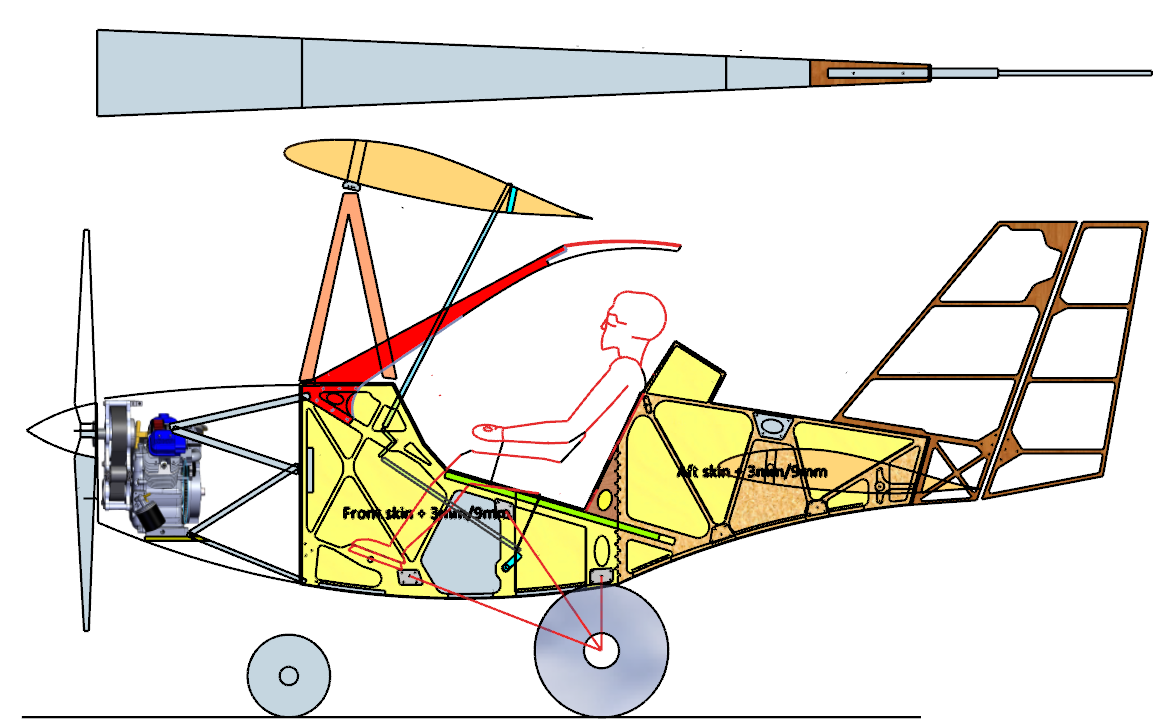
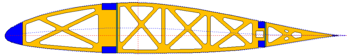
I trial fitted everything, and when satisfied that it all fitted together nicely, bonded the spar caps (blue in the screenshot above). I checked that the trailing edge (4mm glass fibre rod) was straight (it was). I then threaded the 16mm Tassie Oak dowel for the leading edge. Also straight, and a nice fit. I then bonded the LE in.Next job is to bond in the shear webs. They are already cut, so it will be just a matter of slapping on the West System epoxy, and clamping. There are also two 19mm x 19mm drag/anti-drag spars which, although the router cut the holes in the ribs in the correct places, it can only cut at 90 deg, so I have to "angle" the holes so that the spars will fit. And then bond them in place. By this time, the wing should be pretty rigid.I also had to design the wing attachment hardware. The rear wing consists of two halves, separated by the width of the aft fuselage (about 135mm). The inner rib is reinforced, and bolted to a metal attachment on the fuselage. The outer attach point is at the first hinge point. This hardware has been drawn, but not cut yet.Next came the drawing of the wing sheeting. Not as easy as it might sound because of the swept wing. But I've completed that now also. The rear wing will require three full sheets of 1.5mm ply.As you can see - a lot of time at the computer.So much for the wing.I have decided (based on the astute comments here on the forum) that placing the gas tank in front of the firewall - while convenient, because I could use a regular 20 litre gas tank from Bunnings and some fittings from boat shops, this was a terrible position not only because of the proximity to the hot engine, but also in terms of the change in CG as the gas gets used. So I've moved it to inside the fuselage directly on the CG.
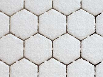
The grey area inside the fuselage in the screenshot above is the new position for the gas tank, with a filler cap jutting through the side just under the pilot's knees, out of the way. About 18 litres (about three hours flight time). I'll have to fabricate it. I thought of plywood sealed with vinylester, but it strikes me that I have a whole box of 3D Core foam, which looks like this:
Extremely light, very easy to cut on the router, and simple to laminate with a layer or two of vinylester and glassfibre. I'll prototype the tank out of cardboard, and then Bunnings plywood before I commit to the actual tank.So that's what I've been up to since last time I wrote. As usual, comments welcome.Regards,Duncan
-
I've been looking at the fuselage, and yes, there is plenty of space directly in line with the CG inside the box. Easy filler cap jutting through the fuse side comfortably below the knee joint. And since the seat is screwed on (not bonded), I should be able to get the tank in/out. This will work. Now I just have to Google how to make a composite tank. Ha ha. Thank you so much for these gotchas guys. I really appreciate it.
-
I spoke to Jared Smith from RAAus yesterday about the Fleabike, and he put me on to Bill Oakes who doesn't live too far from me. I'll contact him on Monday and discuss when would be a good time for him to drop by and inspect the fuselage. Duncan
-
Hi Kasper, I briefly considered a wing tank, but dismissed the idea because I thought it would affect the wing movement in flight. But if, as you say, this is not the case, then I'll definitely look into this. What would be a good material for this? There is a thread on one of the other forums about plywood gas tanks - suitably sealed, of course. Lots of varying opinions. Major drawback seems to be weight. But I guess aluminium would be preferable, except that I have no sheet ali skills or tools. Thanks.
-
Hi, I have also been uncomfortable with the gas tank position. It needs to be closer to the CG, but that is easier said than done. But you raise a very good point.
-
Sikaflex structural adhesive? I'll Google it. Thanks. Actually, Caboolture isn't that far from me. Thanks for the heads-up.
-
I'm confused. The heat distortion temperature of West system is 50 deg C.. Bote Cote is 55 deg C???
-
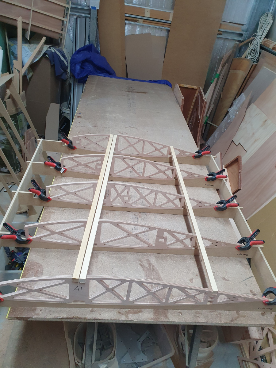
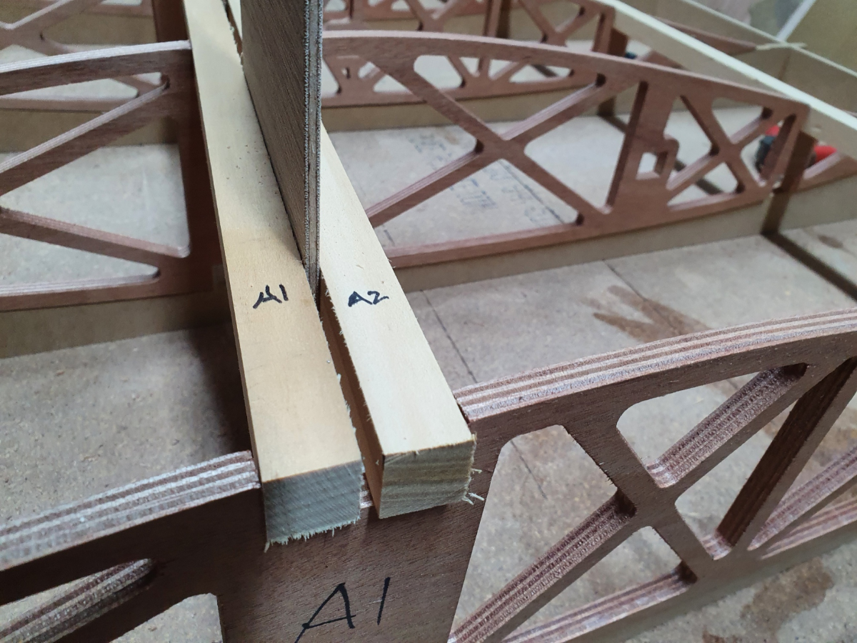
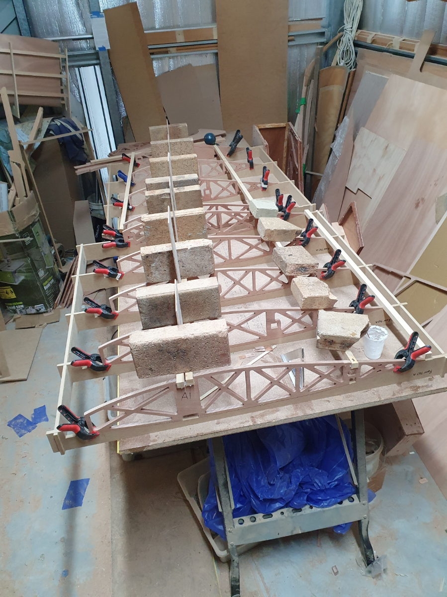
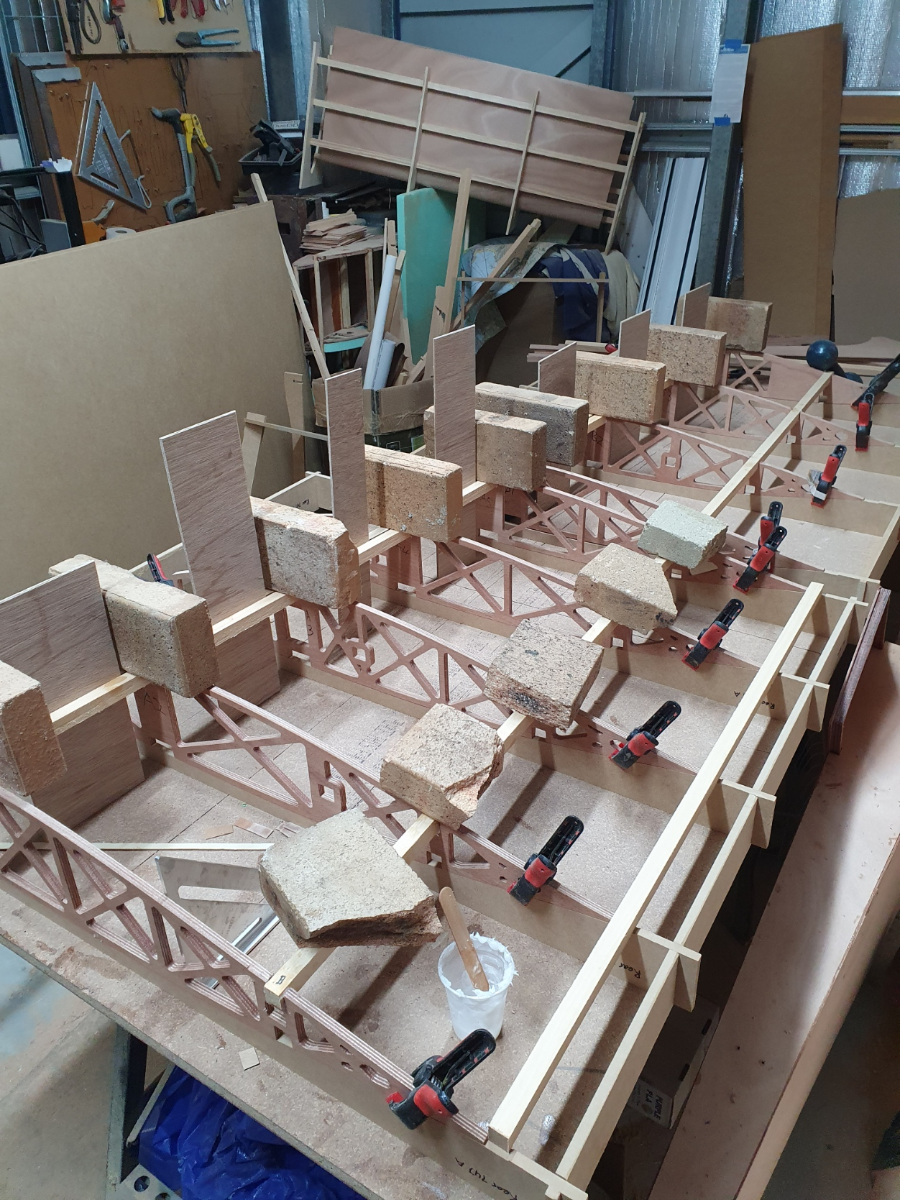
After a rather disastrous laptop infection by a virus which encrypted every file on my backup drive (thank goodness it wasn't my C drive) I finally found time to get back into the workshop and progress my wing. My wings are constructed in three panels on each side. Each panel hinges. Panel A is fixed, Panel B hinges upwards, and panels C/D hinges downwards, allowing the entire rear wing (5.75m span) to fold into a 2m wide "concertina" This is Panel A. Each rib sits in a cradle, ensuring there is no twist, the ribs are perfectly spaced and sit at 90 deg. The main spar consists of two 19mm x 19mm Hoop Pine spar caps, with a 4mm gap between them. This is to allow space for the (discontinuous) shear webs to be bonded in place between them. I know this is somewhat unusual - to have a discontinuous shear web - but I've had the numbers crunched, and the 9mm gap between each shear web segment is fine. Here's a close-up of the spar caps. Using West System with some adhesive filler, I bonded the spars in place on both panel A and panel B. Once satisfied that everything was true, and that every rib was at 90 deg, I weighed the spar caps down with my trusty bricks. By tomorrow morning, I should be able to flip the two panels, and bond the bottom spar caps in place. If I get an early start (and if it's not too cold) I might be able to start sanding the spar caps to the contours of the ribs. Regards, Duncan

-
Gave RAAus a call this morning. Office directed me to Tech Documents, section 3.1 All seems pretty clear. Then I went to join as a non-flying member, but the website wouldn't accept my application because I needed to supply a doctor's certificate to prove that I am fit to drive a car. This, for a non-flying member. Seems odd...
-
OK, I've come up with a plan to take the pain out of sealing the ribs:
- Tell CAM that you are cutting perimeter with 6mm bit
- However, cut with 3mm bit
- Rib will be 1.5mm oversize
- Dip entire rib in shallow bath, filled with polyurethane varnish
- Use a brush to squish the poly into all the cut-outs
- Set aside on plastic sheeting to dry
- Rub down with fine sandpaper to remove fiber rise
- Dip again, set aside and allow to dry
- Then replace ribs in the CNC, re-cut the perimeter, but use a 6mm bit this time
- This will remove the excess 1.5mm all round, and present a clean surface for the epoxy to bond to
There's nothing I can do about the current crop of ribs, but they represent only one half of the rear wing.
Duncan
-
Hi. I'm busy sealing the ribs at the moment. So far, this is BY FAR the most tedious job. I'm rolling the polyurethane onto the sides of the ribs which takes all of about 5 minutes. But every single cutout in every rib has to be sealed as well, and this is a pain in the arse. Only completed four ribs so far. Having a tea break and gathering my loins for another four. Aaargh!
Typical rib:
-
As usual, a sane and common sense response. Thank you. Problem is, though, I plan to live well into my 90's (yeah, right...)
-
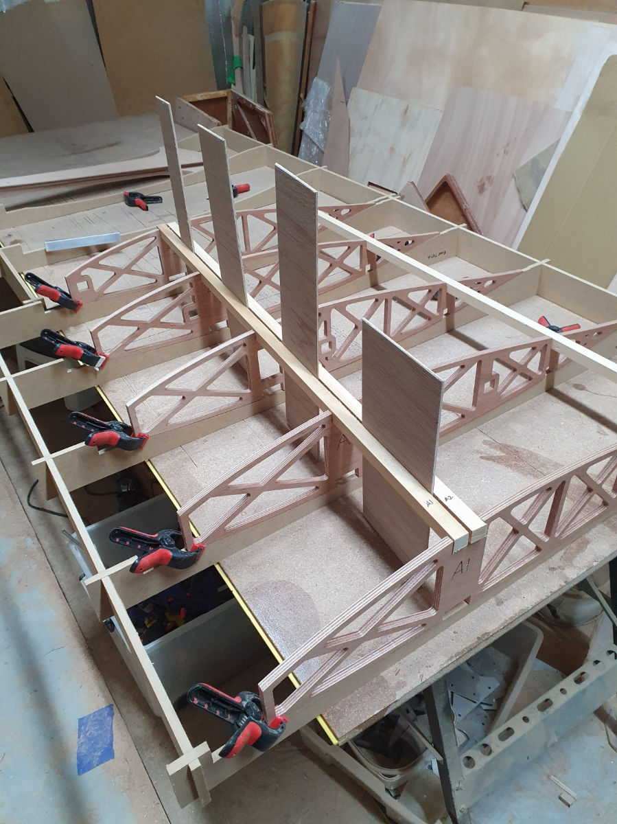
Well, all ribs cut, and all four rib jigs cut. This is the first panel. Unfortunately, the entire wing half won't fit on my build bench. Mmmm. But since they need to be built separately, that's not an issue - just that it would have been nice to see the entire wing - especially since the last panel sweeps up and backwards quite dramatically. Oh well. The jig holds the ribs nice and square. One thing I still have to do is to angle the square cut-outs for the drag/anti-drag spar. You can see the fancy cut-outs in the ribs to accommodate the drag spar. Quite sexy. The CNC cuts them at 90 degrees. But not a big deal. I'll be sealing the ribs next. I was planning on using West System - but that's a very expensive option. So I got some Polyurethane sealer. I'll do that tomorrow. Fleas generally have the pivot at about 23 deg or so of chord. But since this is a tapered wing, I had to calculate the AC first, and then work out 23% of the MAC. Again, no big deal, but easy to miss. I'll also be attaching the pivot masts to a variable attachment, allowing the pivot to be moved from 22 deg of the MAC to about 24 deg. Final positioning can be determined during testing.
-
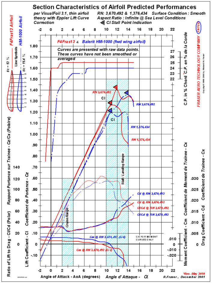
Done! Cut the rear wing ribs using the NACA747A315 airfoil. Nice and fat. A CmMax of 0.012. We'll see how it goes. Also cut the rib jig. Cooking with gas! Photos tomorrow. Duncan
-
As you say - the 23xxx is very thin. Not a lot of meat there. Perhaps my initial choice of the 747 might be a better choice, and my larger than average wing (6.9m, 5.7m span) will compensate for its relatively low ClMax? My router bits arrive this afternoon, and I'm itching to begin cutting ribs... Duncan
-
OK, so the Fraser airfoil seems a poor choice. The only thing I am hesitant about regarding the 747 is it's low Max Cl (1.36) Both the 23xxx airfoils seem to have a max Cl of about 1.5 Is there any value in something like a 23115? I might just play it safe, and go with the 23112... I'm busy researching Roncz, Horten and Hepperle at the moment. Duncan
-
OK, so the Fraser airfoil seems a poor choice. The only thing I am hesitant about regarding the 747 is it's low Max Cl (1.36) Both the 23xxx airfoils seem to have a max Cl of about 1.5 Is there any value in something like a 23115? I'm busy researching Roncz, Horten and Hepperle at the moment. Duncan
-
With regard to airfoil choice, it seems there are a number of contenders. The tried and true NACA23012 the supposedly superior NACA 23112 the 43015 (spoken highly of, but for which I can find no coordinates) the F5Fras15 (lower Cm that the 23012 or 23112 above) and out of left field somewhat the NACA747A315 (it has a very low pitching moment, good stall characteristics, and extremely low drag) I had been planning to use the 747A315, but the F5Fras15 is very attractive. I particularly like the rock-steady CP position, and the low Cm (0.05 in the cruise condition) Any thoughts/advice/experience with any of these airfoils? Regards, Duncan
-
Thanks for the info guys. I'll give RAA a call today. I got Peter Leonard round a month or two back. He looked the fuselage over, and was very happy. He said he'd put me in touch with someone to walk me through the process, but that turned into some documentation sent via email only. Since then I have built a second fuselage incorporating all the lessons I learned in the first one. Very easy to see inside, however, even though it is now all but finished, because a number of panels are screwed on, rather than bonded. Thanks again, Duncan
-
OK, I have a PPL, gained in New Zealand about 15 years ago. I understand I would need refresher courses in Nav, Law, Radio and probably a few others. That's fine, and I accept that. And I'd need some serious refresher stick time also. I'm now 69, so medicals are going to be a problem I assume. Duncan