duncan_rtfm
-
Posts
78 -
Joined
-
Last visited
Content Type
Profiles
Forums
Gallery
Downloads
Blogs
Events
Store
Aircraft
Resources
Tutorials
Articles
Classifieds
Movies
Books
Community Map
Quizzes
Videos Directory
Everything posted by duncan_rtfm
-
Steel tube for landing gear?
duncan_rtfm replied to duncan_rtfm's topic in Aircraft Building and Design Discussion
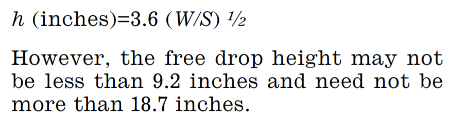
I came across this: However, nowhere is the term "S" defined. They do define "W" as weight (thank you). Aaaargh! However, from 9 to 18 inches seems about what I'd expect... https://www.govinfo.gov/content/pkg/CFR-2010-title14-vol1/pdf/CFR-2010-title14-vol1-sec23-725.pdf
-
Steel tube for landing gear?
duncan_rtfm replied to duncan_rtfm's topic in Aircraft Building and Design Discussion
Since objects fall at a rate of 32 ft/sec, the duration of the fall would need to be quite small - nowhere near 20 ft. More like one or two feet at most I'd think -
Steel tube for landing gear?
duncan_rtfm replied to duncan_rtfm's topic in Aircraft Building and Design Discussion
Thanks for the comments. I know the Aeromax has rigid 3-point suspension and relies only on the fat 18-inch low pressure tyres for damping. I should give David Trump a call and get his thoughts on this. Duncan -
Steel tube for landing gear?
duncan_rtfm replied to duncan_rtfm's topic in Aircraft Building and Design Discussion
Excellent info kasper. You're right, mostly known, but I thin k I may have underestimated the compression on the secondary members. Thanks for the reminder. I've been looking at 25mm square aluminium also, rather than steel. Not sure about this however. Duncan -
Hi, I'm looking for 3mm mild steel sheet. I certainly don't need a full sheet (about 500mm x 500mm should do nicely). Any ideas? Thanks Duncan
-
Hi, I'm at the stage where I need to start fabricating my main gear. The design calls for three triangulated steel tubes without suspension, relying rather on the cushioning effect of the 450mm balloon tyres. The plane is going to be very light (MAUW of about 300kg) so this should suffice. I have 25mm OD steel tubing in the shop which I was going to use, but I'm beginning to think that the 1.2mm wall thickness isn't going to cut it. Any suggestions? Experience? Regards, Duncan
-
Do birds do recreational flying?
duncan_rtfm replied to nomadpete's topic in Aircraft General Discussion
Some years ago my wife and I visited Muriwai (on the coast near Auckland) and watched fascinated as hundreds of Gannets did great big circles out to sea and then back towards the rocks, skimming the cliffs by mere inches. And then off they'd go again for another circuit. I followed a single bird on his circuit, and he flew with amazing precision, time and time again. Truly amazing. Just having fun it looked like. -
Hi,
Anyone know where I can get decals/stencils/wrap to apply to my white-painted fuselage and wings? (I'm in Brisbane).
-
Hi, I assume that the further aft the CG is from the main gear, the more difficult it will be to keep a tail dragger tracking straight down the runway, and vice-versa. Are there guidelines for this? Raymer suggests an angle of from 16 deg to 25 deg from the main gear to the CG. My undercarriage can be swapped left/right to convert the Fleabike from a tricycle to a tail dragger, so I'm looking for some real-world experience from guys who have flown well-behaved tail draggers. Any advice? Duncan
-
Hi, So very sorry to hear of your health issues. It's a sad day - and one which is down the road for all of us eventually. Good luck with the sale.
-
During SEQ's lockdown I've been champing at the bit, because I have been waiting for a wood delivery to carry on work on the Fleabike. So, with nothing else to do, I have designed a new plane - this time a fully enclosed single seater.
I've decided to build it with the cedar strip canoe method. I have watched a huge number of Youtube videos of people building strip canoes, and it all looks reasonably straightforward. However, all the online builders are working from plans, and don't have to make any design decisions.
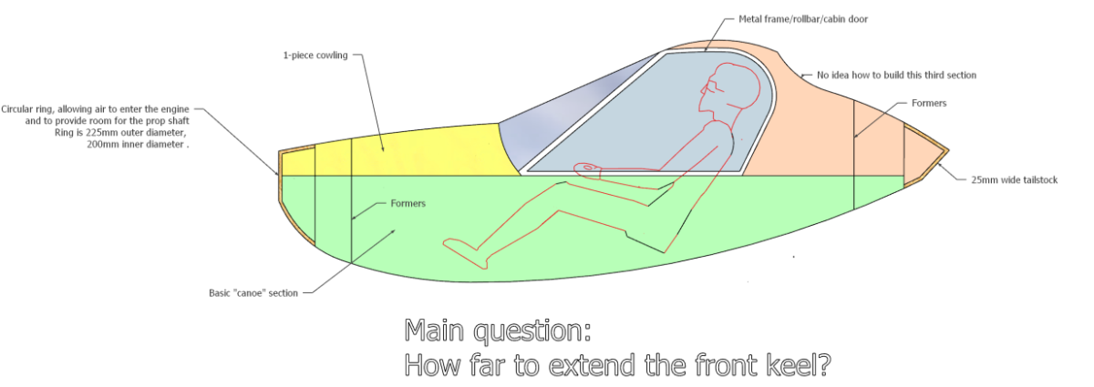
My first design decision is how far to extend the front "keel". It has to accommodate a 225mm diameter ring (to allow air into the engine compartment, and to provide for the prop shaft). I don't actually know how to build this.
This is what I've come up with so far...
I'll build the fuselage in three sections. The green section is a fairly straightforward "canoe". The yellow section is a single piece cowl/engine covering. And the orange section (as you can see) comprises the roof and the turtledeck
Do I run a keel along the entire length of the green section? And the yellow? Or do I do this for all three sections?
Are there any canoe builders on this forum who might be able to help with this?

Regards,
Duncan
-
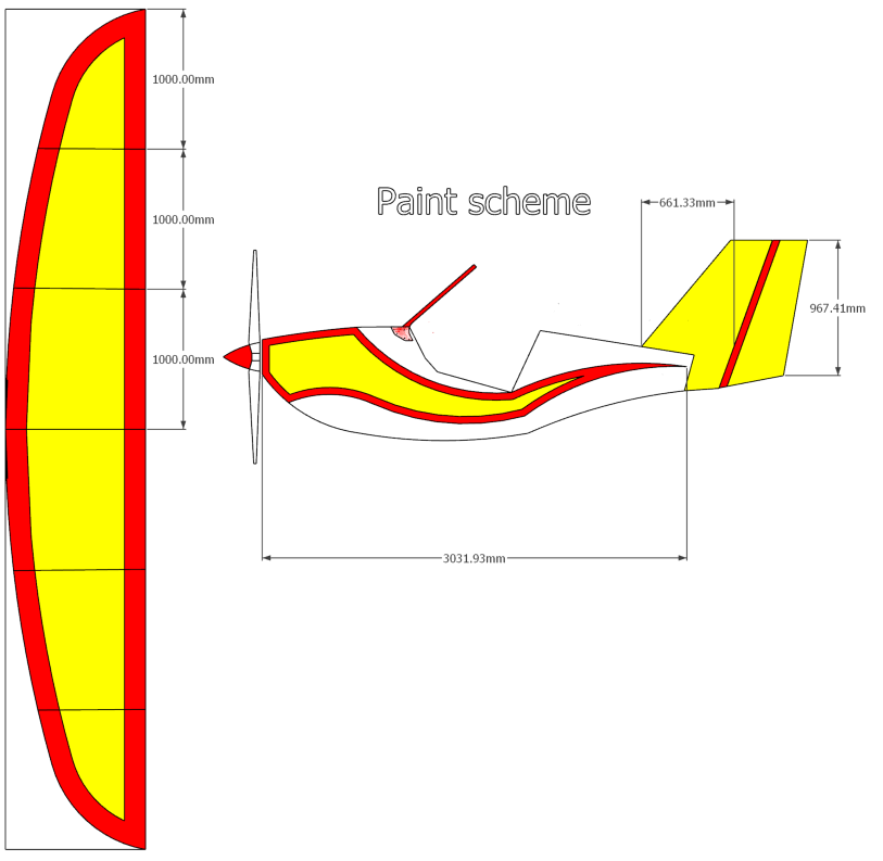
OK - the Fleabike fuselage is complete, windshield added and all sanded down. Any suggestion regarding how to paint the Bike?
I have some 117 fairing additive for West system, and I thought I might roll that on, sand it back and paint with West + pigment (white). I'm leaving the control panels, seat, seatback (i.e. the upper central spine) natural wood, but painting the rest.
Is there a better way?
-
Tensile strength of Hoop Pine?
duncan_rtfm replied to duncan_rtfm's topic in Aircraft Building and Design Discussion
Hi, Plenty of maths involved in the optimal placement of CG, wing articulation (front and optionally also the rear) and so on (in fact I wrote a whole 30-page paper on this), but as kasper says, a lot of the rest draws heavily from existing designs (for example, the HM293 on which the Fleabike is firmly based) and others. As far as the undercarriage is concerned, after some initial thought experiments (quickly shot down by experienced and knowledgeable forum members, both here and elsewhere), it is now essentially the undercarriage of the HM293 prettied up a bit. Same for the wing masts and braces. Regards, Duncan -
Tensile strength of Hoop Pine?
duncan_rtfm replied to duncan_rtfm's topic in Aircraft Building and Design Discussion
Interesting. Well, certainly cheaper than 4130... Me? Whack the ground? 😄 -
Tensile strength of Hoop Pine?
duncan_rtfm replied to duncan_rtfm's topic in Aircraft Building and Design Discussion
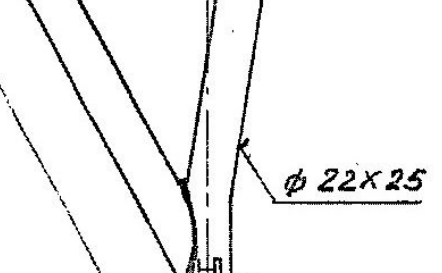
I've just checked my HM293 plans, and it seems that they specify 25mm OD, 22mm ID. Am I reading this correctly?
-
Tensile strength of Hoop Pine?
duncan_rtfm replied to duncan_rtfm's topic in Aircraft Building and Design Discussion
I concur. 25mm it is. I'll keep my box of 20mm foam riblets for another project perhaps. Ha ha - I have so many let overs from this project "perhaps for a future project" that I need a separate shed to house them all! -
Tensile strength of Hoop Pine?
duncan_rtfm replied to duncan_rtfm's topic in Aircraft Building and Design Discussion
Hi again, I am equipping the Fleabike with 18-inch tundra tyres, and no spring damping at all. I am relying on the big soft tyres to do all the damping for me. But yes, a study of the HM293 is certainly on the cards today. Duncan -
Tensile strength of Hoop Pine?
duncan_rtfm replied to duncan_rtfm's topic in Aircraft Building and Design Discussion
Hi, See post above/below. Various lengths. My only concern is whether I need to go with 25mm tube vs 20mm OD Duncan -
Tensile strength of Hoop Pine?
duncan_rtfm replied to duncan_rtfm's topic in Aircraft Building and Design Discussion
Hi, Good to hear that our methods are identical, if not the means of getting the riblets cut. I also intend to cut end plates out of ply, and a straight sanding block to tidy up any bits and pieces. Mine are now cut and in a box. The only trouble is I made the steel strut hole 20mm OD - I'm thinking I should have made it 25mm? Thoughts? The carbon rods are just for alignment - they get removed when the foam has been bonded. a one metre length of 4mm CF rod is about $8 from hobby shops. Similar aluminium/brass etc is a bit cheaper, but this is a tool, not part of the strut. Buy once, use many times. It just depends on the most convenient purchase. I also checked on the price of streamlined 4130 steel tube - but at over $80/metre, that's not going to happen. I need this for two front wing masts (650mm each) Four rear wing struts (460mm and 520mm) Six main gear legs (1000mm each) Regards, Duncan -
Tensile strength of Hoop Pine?
duncan_rtfm replied to duncan_rtfm's topic in Aircraft Building and Design Discussion
Hi there, All options are on the table at the moment. I'll probably end up giving a few of them a go, and seeing which one works best. But the folded AL sheet idea is a good contender. Might be the subject of a nice photo-post for all to see. Duncan -
Tensile strength of Hoop Pine?
duncan_rtfm replied to duncan_rtfm's topic in Aircraft Building and Design Discussion
Hi guys, Thanks for your suggestions, but I've given this some more thought, and because I don't have any of the kit needed to hotwire foam, this is what I've decided to do. Materials required: 2x 25mm steel (or aluminium) tubes 1x sheet XPS foam (local hardware store, $12.50) 2x steel/aluminium/brass/carbon fibre rods (4mm diameter) Method: Chop the foam sheet (1200mm x 600mm x 30mm) into a zillion 100mm chord "riblets" Grease up the tube and the big hole in the riblets with West epoxy Thread required number of the riblets onto the steel pole, bonding each new one to the preceding with some West Thread the two brass/aluminium/ carbon fibre rods through the 4mm diam alignment holes Wait for it all to set Rinse and repeat All that's left to do is to affix the attachment hardware to the ends of the steel/aluminium tubes, and to coat the foam with a layer or two of epoxy and possibly a layer of glass fibre. There are enough little riblets in a single sheet of XPS from from Bunnings to make several struts for several planes. Just sit back and watch the router do its magic. Of course, hotwiring things would be easier, but as I say, I don't have the kit.
-
Tensile strength of Hoop Pine?
duncan_rtfm replied to duncan_rtfm's topic in Aircraft Building and Design Discussion
Thanks for your help gents. -
Tensile strength of Hoop Pine?
duncan_rtfm replied to duncan_rtfm's topic in Aircraft Building and Design Discussion
Hi, Yes, I came across that one, but no tensile strength listed. I'm wanting to carve wing struts out of hoop pine, and need to know if the wings will fly off on their own at 1000 feet... -
Tensile strength of Hoop Pine?
duncan_rtfm posted a topic in Aircraft Building and Design Discussion
Hi folks, Does anyone know the tensile strength of Hoop Pine? I've looked everywhere, and can't find it. Thanks, Duncan -
Question:
After wasting about an hour (and two cups of coffee) on the laptop searching for suitable fuel drain plugs, not a single manufacturer/distributor cares to specify the diameter of the thread going into the fuel tank. It seems I am looking for a 1/8" NPT, but I need to know what size hole I need to cut into my tank to accommodate this. Any ideas?
Duncan