rotax618
-
Posts
171 -
Joined
-
Last visited
Content Type
Profiles
Forums
Gallery
Downloads
Blogs
Events
Store
Aircraft
Resources
Tutorials
Articles
Classifieds
Movies
Books
Community Map
Quizzes
Videos Directory
Everything posted by rotax618
-
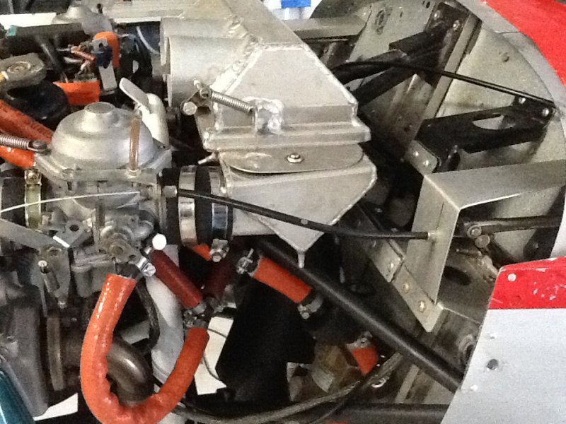
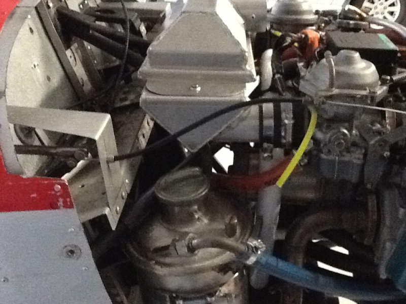
The 618 engine requires two jet sizes -# 135 for PTO carb, #145 for the MAG carb. It is the only Rotax 2 stroke with this requirement. The 618 is a very reliable engine, it weighs considerably more than the 582 even though they share the same pistons, the weight is in the very strong crankshaft. The performance difference between the 582 and 618 is chalk and cheese. The 618 is a detuned 670 snow mobile engine, the 670 is single ignition and is rated at 135HP. Unfortunately the 618 requires a very large and heavy oval muffler. Although the RAVE valves automatically open by air pressure at altitudes less than 5000 ft they should be connected to a cable so that they can be cleared and exercised prior to and after every flight.
-
I found that if the a fuel cap isnt sealing then a air bubble can form at the top of the reserve tank causing the low fuel light to come on. The reason for this phenomenon is the low pressure air in the boundary layer on the upper wing surface, ICP attempts to fix this by passing the cap breather tube through the wing to the high pressure botton side. I changed my breathers to forward facing hockey stick tubes facing forward on each cap and purchased some better cap seals from Reg.
-
We tried straight rods on a VG years ago and found that the forward movement of the engine on the bed mount pulled the throttle back from WOT when the throttle linkage was adjusted to the forward stop when the engine was stopped. If your system works ! Great.
-

-
From my measurements the 701 and Savannah VG have the same firewall, the Savannah XL and S have the same width firewall but at about 6deg less rake. I have no knowledge of the 750.
-
The top X-member that carries the thrust bearing , throttle etc has been known to crack at the ends at the bend up against the firewall caused by rebound shock. Most of the cracking of the lower fitting is caused by the stops on the leg used to limit the vertical movement of the leg when the aircraft is dropped onto the nosewheel. There are consequences when a fitting is strengthened and made more rigid, it simply transfers the stress, the Nomad aircraft tail cracking modifications demonstrated this admirably. Marks modification looks OK and probably should be included in the kit, the stops on the leg are not a good solution, as the leg is weakend at the point of greatest stress by the holes and the bump stop was never designed to take that force.
-
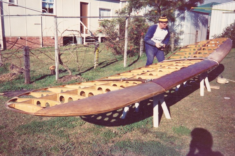
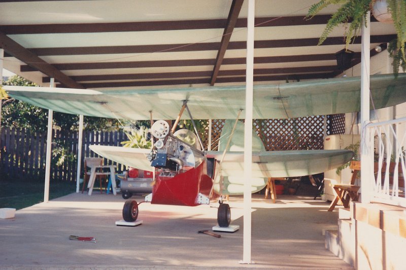
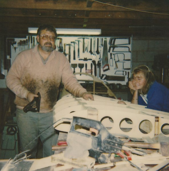
My flea had a standard length fuselage as per Henry's book "Sport de la Air"? The few times I got it off the ground I found it very stable in pitch but because of the enormous flying rudder and short couple was neigh impossible to keep straight. The 40hp Robin was adequate power, less power would certainly require more wing span/area. This is another photo of a friend helping to prepare the front wing for covering.
-
Just a few more photos of the flea construction.
-
I mentioned the change to a 503. I had sold the Robin engine and re-drive to Mark Fisher who was going to use it to power a Strognik? S2A Motor glider, Mark sold the incomplete motor glider to someone in WA, havn't heard if it was ever completed. It's a shame Fred's health failed not long after he sold our Flea, he had some great ideas on Flea design and development. I havn't heard from Fred for several years, and given his poor health I fear the worst. I lost interest in the Flea concept and have designed and built several 3 axis aircraft since then.
-
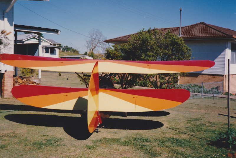
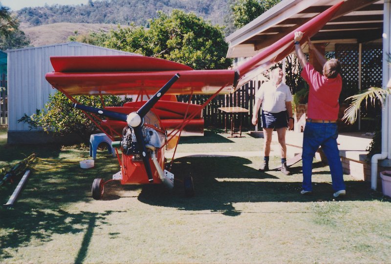
I built an HM14 with HM293 wings 25years ago, I powered it with a Robin 440 with a homebuilt V belt reduction. I had a number of attempts to fly it but because of the lead/lag delay in yaw/roll, once off the ground I couldn't keep it on the centreline of the strip with PIO dutch roll phugoid roll/yaw. Some years later Fred Byron asked if he could play with the problem and replaced the all flying rudder with a smaller fin and rudder and cut a Cosandy? Flap into the rear wing and re-powered it with a Rotax503. The Flea was subsequently successfully flown and then sold to an American collector.
-
The nosewheel problem is far more pronounced in the XL and S models because ICP in their wisdom decreased the rake or caster of the nosewheel leg by 6deg over the VG to get a sexier more raked windscreen. This decreased castor places a great deal more stress on the leg and its attachment.
-
Sad to hear, was talking to him at the Great Eastern Evans Head. A true pioneer and promoter of the ultralight movement.
-
I did not reply to you concerns regarding CG forward movement at a nose high attitude, the effect of the movement of CG at various angles of pitch will be less than that of a conventional high aspect planform because CG in low aspect planforms is far less critical simply because of the chord.
-
The pendulum effect will dampen both pitch and roll as Bex said "thats physics" but unless your mission is aerobatics it is a lot more pleasant to fly an aircraft that has positive stability. The pitch stability may be a safety factor that may dampen any extreme nose up attitude that could lead to the craft getting behind the power/drag curve an going into a parachute like descent. Aircraft like the Thruster are not adversely effected in their ability to flair by their high wing. At any rate you should build a reasonably sized model to test all regimes of flight before building a prototype.
-
Visibility is always a problem if you sit above a very wide chord wing with a tractor engine configuration. Bex you will probably find that the pilot will have to be placed further back when you factor in the weight of an engine in the nose if you intend to keep the wing loading as low as possible. The pendulum effect of a high wing with a circular or elliptical planform may make the craft too stable in roll, no dihedral is required for roll stability, indeed the FMX4, both of my models and the UFO had no dihedral or had anhedral and were very stable in the roll plane you will need to experiment to determine that. One additional effect is worth noting, that is the "dead air" in the wake of a very thick low speed wing. David Rowe's UFO has very large control surfaces and the later models of Hoffman's Arup had a very small tailplane and elevator fixed near the top of the fin as well as elevators (presumably for trim) attached to the rear of the wing, and later versions of the Dyke Delta had a horizontal all flying small control surface up on the fin. I would use "Junkers" type elevons which would alleviate the problem without adding much drag. I hope to build more models and continue my experiments but am no longer physically agile enough to undertake the construction of any more full size aircraft.
-
I have many sketches and drawings, I've attached 2 examples with long and cross sections which show what I mean about approximating to a "conventional" aerofoil . I like the raised cockpit of the faceted design and the efficiency of the curved shape. Curved lifting body.pdf Faceted lifting body.pdf Curved lifting body.pdf Faceted lifting body.pdf Curved lifting body.pdf Faceted lifting body.pdf
-
I have some designs for a simple "Smoothmobile" I will post them to the forum as soon as I can get back to my main PC and figure out how to post a PDF. You are welcome to use any of the ideas to build a model to carry on the experiments and hopefully a full sized craft. One of the problems in building an "ultralight" all winged aircraft is to find a lightweight covering material, the actual internal structure can be light and simple because the short span and deep spars. I once looked at building a 95.10 craft and covering it with the heavy weight shrink wrap plastic sheet that they use to transport boats, it is quite strong and can be glued to the structure has pretty good rip-stop properties and doesnt require any finishing. Another problem is that unless the craft is built in three pieces the it has to be built at an airport as it will be as wide as it is long. I used an approx 8' centre section with folding or removeable tips.
-
G'day, my experiments are limited to three faceted lifting body aircraft and a larger number of hand launch gliders. We first built a model of the Facetmobile, which flew reasonably well while under power, but had an horrendous power off glide. To understand the poor aerodynamic efficiency simply draw some longitudinal section from the centreline to the wing? tip of the FMX4, you will see the very large amount of washout, I think the Designer did this for reasons of safety but the result is a very poor overall L/D. I designed another faceted lifting body but ensured that the washout problem was fixed and the longitudinal sections approximated to a "normal" aerofoil at a normal angle of attack, the result is the model you can see in the Youtube clip I posted several years ago. The model was the same size and weight as the Facetmobile model but as you can see it has an excellent L/D as well as vortex lift at large angles of attack and no perceptible stall. No matter what shape the planform these low aspect ratio aircraft have no magic method of overcoming the high induced drag associated with a high span loading, they limit the adverse effects of the induced drag by having a much lower wing loading and using the vortex created by the planform to increase the lift at high angles of attack for a very low landing speed. You should aim for a wing loading not much more than about 60% of a conventional planform aircraft designed for a similar mission. It is not difficult to have a low wing loading because they are all wing. My third model was to investigate a slightly different arrangement and simplification of the facets, it had a far better L/D than the FMX4 but did not fly as well as the MK2 model. I have to thank my friend Danny Leach for building the models to my designs and his skill in flying the models.
-
Be careful where you drill the holes to mount the sight gauge fittings, if the holes are drilled too close to the top and bottom of the tanks when you tighten up the fittings the plastic tanks will crack, the fittings must be seated on the flat surface of the tank NOT too close to the curved edge. I was given a tank that had split at the return fitting, I was going to get the tank welded up but the plastic couldnt be successfully welded.
-
This is one reference there are several more - note the increase in L/D where the AR < 1.5 http://naca.central.cranfield.ac.uk/reports/1933/naca-report-431.pdf
-
I dont know how to caculate the MAC for these planforms but I observed , after making circular, elyptical zimmerman and reverse zimmerman chuck gliders out of foam in all of these shapes that the CG of these planforms with AR of about 1 - 1.5 is at approx 33% of the root chord from the LE provided that there is sufficient reflex to control the pitching moment. The CG position is not as critical as a plank or a swept Horten flying wing because of the AR.
-
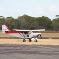
I believe that the early model tail dragger skyfox was only 450kg MTOW, with 80kg pilot + pas you were already overweight without fuel and baggage, later models were 520kg MTOW.