sain
-
Posts
518 -
Joined
-
Last visited
-
Days Won
1
Content Type
Profiles
Forums
Gallery
Downloads
Blogs
Events
Store
Aircraft
Resources
Tutorials
Articles
Classifieds
Movies
Books
Community Map
Quizzes
Videos Directory
Everything posted by sain
-
the 100n capacitor that Zulu1s talking about simply blocks D.C voltage travelling between the microphone element and the radio, but will still allow the AC audio signal to travel. This means you can add a seperate power supply (the AA battery) to power up the microphone and eliminate all the nasty squeal you've been getting, without frying the audio input circuitry in the radio. The other bit with the ferrite bead and other capacitor is to elimnate noise being induced on the line... The radio itself makes use of 7v, but only 5 on the microphone line (i'm guessing here, based on what zulu1 has said - I don't actually know and can't be stuffed looking it up). The good news is that Zulu1s fixes will only cost a few dollars and should solve the problem.
-
Congratulations on the GFPT and welcome!
-
Congratulations Karen, well done. To handle the dehydration problem myself I take a camelback (actually by another, cheaper, company but hey) along with about 2-3 litres of water in it. That way I can drink from it as I'm flying along and doing other things with my hands . The only important thing is to remeber to take the tube out of your mouth before making radio calls, lest you drown your headset microphone. While solo it just sits on the seat behind me, for duals I just wear it like normal - its quite comfortable. One thing I found helps a lot on navexs is to take along an inflight meal (starbursts or jellybeans or lollipops or something) to distract the instructor with.... (perfect if you've screwed up and need a quick diversion to fix it - just "encounter some turbulance" as they are opening the bag). Seriously though, it does help a lot with maintaining comfort and attention, and if your instructor has had a busy day they'll probably be greatful for the snack while they are hoping you get lost so they can see some different scenary for once. Airsick, personally i find the 10 mile markers make more sense to me, especially on those days when the forcast is out by a fair bit (my first solo nav was forcast for 15... started at about 3-4kts, wound up roughly 15ish on my final leg). I know one of the other guys at goulburn much prefers the 10 minute markers.. I guess it comes down to personal taste. You could always mark both and see which one you end up using.
-
Well, that was a nice experience... A little while back I lost my nav whizzy wheel, and had completely forgotten about ordering another one until today (with a flight booked for saturday). In a bit of a panic (because i hate looking like an ass turning up without my equipment) I tried ordering one from the clearprop site. Unfortunately the Australia post lookup stuff was causing troubles, so I left a message asking for help. A short while later I received a very curtious phone call from Ian, who handled everything quickly and effeciently - not at all what you expect from an online shop. Thanks Ian, wonderful service! alrighty, i'm ready for my no advertising ban...
-
Electronics Project - Quad CHT Gauge
sain replied to sain's topic in Aircraft Building and Design Discussion
Well the whole programmer build thing did not go well, though entirely due to me rather than the circuit. I built the thing on friday evening, and gave it a test run. Unfortunately it did not work, so I spent a couple of hours or going over the circuit and making sure I hadn't got anything backwards or forgotten a connection somewhere. Unfortunately I didn't find anything wrong, so I tested it again and it still failed. At this point I gave up in disgust and went off to do other things. On monday I had another look at it, and after going over the whole lot again I picked up the breadboard to get a closer look at a transistor (thinking I may have swapped two inadvertantly) and the PIC fell out - i'd forgotten to push the leaver down on the ZIF, and the chip sitting in it doesn't make the connection properly unless its down. So I put the PIC back in, pushed the leaver down, gave it a test program and it worked flawlessly. At that point I decided I was too frustrated at my own stupidity to do any more work on it and went to watch scrapheap challenge. Display circuit and program changeover tonight hopefully (to use the new chip), and maybe some thermocouple testing. -
Electronics Project - Quad CHT Gauge
sain replied to sain's topic in Aircraft Building and Design Discussion
Not much progress on this for a while due to budget issues (i.e I blew my toy budget for the fortnight on other stuff). The change to the PIC16f877 microprocessor means I needed to upgrade my el-dodgo PIC programmer to support the new chip. I finally got around to buying all the bits and pieces yesterday and I hope to have the programmer built tonight (a dinner party got in the way of doing it last night). Hopefully I'll also have time to do some test programs, and get the display stuff working on the new chip (should be straightforward). In case anybody is interested I ended up using feng3's multipic programmer circuit (http://feng3.cool.ne.jp/en/pg5v2.html), though I'm building it on a breadboard until I'm sure I'm happy with it. Total cost for the parts on this sucker runs at a few bucks (I think $4.80), unless you buy a ZIF socket (which is a good idea) which bumps the cost up to $30ish. The zif socket makes it easy to swap the chips in and out without damaging them, so its handy if your doing a lot of programming. I've also now got a thermocouple to do testing with. Most of this will be to see if I can get away with out using a seperate cold junction compensator chip. This wouldn't normally bother me, but they just arn't available at jaycar or DSE, which is what i'm trying to use as parts suppliers - so anybody can build one of these. Anyway, the theory is that the thermocouple provides a small voltage which is proportional to the voltage difference at the hot junction (the thermocouple bit, or "sparkplug washer dohickey") and the cold junction. For those of you who got to do experiments in science classes back in high scool (or currently in high school if you happen to still be there), it was the experiment where you had a couple of dissimilar metals joined together in a triangle shape (ish). You stuck one end in the bunsen burner flame, one under the tap and measured the voltage with the millivolt meter. And then promptly evacuated the room, because somebody had accidentally set their school bag on fire with the bunsen burner... or their hair, or the desk, or somebody was holding it at the hot end or... damn science was good fun! although probably not so much for the person with their hair on fire... uhh.. got off topic a bit. Anyway, the cold junction compensator basically allows for the fact that the temperature at the point your measuring the output changes a fair bit, and certainly isn't the ideal 0 degrees. So it measures the temperature at that point, and automatically adjusts the thermocouple output to compensate for whatever the temperature happens to be. My plan is to duplicate this functionality with the PIC, measuring the temperature with a diode (cheap but sneaky trick. transistors also work apparantly) and then adjusting the thermocouple reading by that amount. I'm not sure if this will work, so i'll be doing a fair bit of testing. Feel free to correct my theory if I got it completly wrong. Extra bits bought that are actually needed for the gauge: crystal and other components for oscillator for 16f877: $4.23 Op-amp and other components for getting thermocouple output to a readable voltage: $2.73 Total so far: $32.81 -
Electronics Project - Quad CHT Gauge
sain replied to sain's topic in Aircraft Building and Design Discussion
Good Info - thanks guys. I thought the ones used in the automotive world were fireproof. Easy enough to test I think. -
Gday Shahbaz and welcome. I hope you enjoy your first flight when you have it!
-
Electronics Project - Quad CHT Gauge
sain replied to sain's topic in Aircraft Building and Design Discussion
Well looks like the colour visibility problem doesn't have a particularly easy solution. One option is to use tricolour leds, and drive each colour to a user set level (basically gives a user configurable RGB display). This will be more expensive, as each LED costs $0.50 as opposed to $0.14, giving a cost of $16 for the 32 leds, rather than $4.48. There will also be a number of other components requried, costing roughly $12 (i'd need to work the circuit out to be more specific). The other option I've come up with is to use white leds, covoured by a coloured plastic screen (basically the reverse of the current setup - coloured LEDS and a clear screen). Unfortunately as 3mm white LEDs only seem to come in 1000mcd, 3500mcd or 5000mcd versions there may be some risk of girl friends/wives hijacking the aircraft to use it as a tanning bed (the LEDs i've been using are 15mcd). I suspect that bright sunlight visibility would no longer be a problem. Retina damage on the other hand... okay, got a little carried away in the sillyness... the brightness would be quite easy to control (and isn't THAT bright). cost for this option would come out at $43.20 for the 32 leds (doesn't include the coloured plastic) but is technically far easy to implement. My preference at the moment is to provide a slightly modified design to support option one, which would cost a bit more than the standard version, but should still be quite cheap. Option 2 just comes out as too expensive (your looking at $123 for the leds and thermocouples alone, let alone housing, circuit boards, plugs, microcontroller, other dohickeys). -
Electronics Project - Quad CHT Gauge
sain replied to sain's topic in Aircraft Building and Design Discussion
Thanks very much Ross I'll check that one out too. Unfortunately in brighter daylight the yellow is quite pale (though to me still visible). I'll have to think of an alternative, or maybe just make it 5 green, 5 red - which would also be a problem for one of the guys at my work. The available colour ranges for LEDs are quite limited, so I'm not sure how far I can go with this display type... As a reference the OLED panel I had been thinking of using is $25 + gst in small quantities (and the market isn't big enough to buy large quantities). Not a huge problem, but there is additional complexity in connecting it to the microprocessors. They can certainly display a wider range of colours, and I could allow for some user customisations in the software (so if I get it wrong it could be changed) to get around vision difficulties. If time allows I'll buy a panel and try it out. I'm afraid I'm a guilty party on the pale yellow background for web pages - to me its a a colour which is very easy on the eyes and not at all painful to read for long periods. In future I'll look up information on colour visibility problems before picking them. Sorry about that. My intent here, besides teaching myself, is to provide a low cost, "open source" design that can be built by pretty much anybody, and wont require much in the way of electronics skills (ability to solder will be about it). That said I also intend to sell (through Ian, assuming he's willing to have them in his shop) fully built versions for people who can't be bothered (or don't know how) to build it themselves. Hopefully this will help to fund devlopment of other, more complex, projects down the track. If not it'll just have to wait until I've saved the moolah. Waaaaaaay-the-hell-down-the-track goal is an ADSB transponder, but I've got a hell of a lot of learning to go before/if I ever get there. If anybody has suggestions for those "in between" projects they'd be appreciated. Thanks for your input guys, its been very helpful - please keep it coming! -
Electronics Project - Quad CHT Gauge
sain replied to sain's topic in Aircraft Building and Design Discussion
Thanks for that site Yenn - wish I'd found their DIY section with its audio isolation amplifier before I designed and built my mp3 mixer dohickey, it would have saved me a load of time. Oh well, it was a learning exercise anyway. I was thinking the through firewall connections would be similair to a cars - basically a hole and grommet arangement. I guess the problem with bringing the 4 wires through would be more with the cost of the thermocouple wire - though that looks fairly minimal. The other issue is with every sensor you start adding to the system its another cable that needs to be routed through. I think if I start a third project along the lines of a engine sensor suite (cht, carby temp, oil temp, exaust sensors etc) I'll probably go with the more expensive processor unit in the engine bay, display unit on the dash option. For a project this simple I think its overkill. Anyway, I managed to get some full direct sunlight testing of the LED array done today, and unfortunately it wasn't that crash hot. Basically I had trouble seeing the greens and yellows unless I was looking straight on at them. I'll have to see if this changes once they are in their mounting. For daylight, but not in direct sun, the display was easily visible. I'm not sure how big a problem this is - I don't think it'll be much of one for high wing aircraft, but I suspect it'll be fairly bad for low wing. Can anybody enlighten me as to how often they have their dash lit up by bright sunlight? I'm afraid I just don't have the experience to know. (damn low hours!) -
I thought i'd create this thread to document my progress on my current electronics project, which is a low(ish) cost digital 4 channel cht gauge, with over temp alarms. My ballpark guestimate of final unit cost is $80-$100 not including the 4 thermocouples (which will cost an additional $80 for the 4 at current prices). I'll try and post costs as I'm going. Currently I'm in the early stages of designing the gauge, and learning how the electronic dohickeys work, and figuring out what is and isn't a good idea. If anybody has any input, suggestions or criticisms I'd appreciate them. Down the track i'll also be looking for somebody to test it for me (as I don't have my own plane). The design is currently for a single unit, contained fully behind a 2 or 2 1/4 inch front. The gauge will be 4 columns of 3mm leds, each with 8 leds to indicate temperature (4 green, 2 yellow, 2 red). Brightness will be controlled by either a knob or 2 pushbutton switches on the front of the unit. This display has been built, but still needs testing in bright sunlight (works well in ordinary daylight, and dark low light conditions). The display is controlled by a PIC microcontroller (currently a 16f628a, but will be changed to a 16f877), which will also handle the temperature measurements from the 4 thermocouples. The temperature measurement portion has yet to be built and tested, but I'll hopefully be able to do that during the evenings in the next few weeks. The main drawback with that design is that it will require the 4 thermocouple cables to come through the firewall into the behind-dash area. I'm not sure how big a problem this is, so if anybody has any input it'd be welcome. The other alternative is to go with 2 units, one in the engine bay and 1 behind the dash, and a single wire through the firewall connecting them for data transfer. I decided against this approach as it will approximately double the cost of the hardware required (i.e 2 microprocessors, 2 cases, 2 power regulator circuits, etc etc). Schematics and photos to come eventually. Costs: Pic16f877 Microcontroller + 32 Leds + 4 transistors + variable resistor (quick and dirty brightness control): $25.85 It should be noted that the costs don't include the circuit board cost, or the case cost at this stage.
-
Electronics Project - audio mixer for headsets
sain replied to sain's topic in Aircraft Building and Design Discussion
The per cylinder pressure gauge idea is very interesting. The sort of pressure sensors I've been able to find certainly have the capacity to respond that quickly, but wont work in those temperatures. I havn't been looking hard though. I'll keep thinking on it. The display brightness is certainly a problem I've been considering. I was just going to provide a brightness control on the front panel (probably 2 push buttons) to allow the pilot to change the setting in flight. The other option is to have a few preset brightness levels - i.e bright daylight, lowlight daylight, night, etc etc. I think the continually variable range is a better option personally, and, happily, easier to implement. -
Try Goulburn aviation. Only about an hour or so drive from canberra. The guys at the canberra aero club may also be able to point you in the direction of somebody who can help.
-
Do ou have a turbulance technique??
sain replied to motzartmerv's topic in AUS/NZ General Discussion
It might be worthwhile going for a few rides in a glider, to see the kind of things they look for. After all, thermals are just turbulance to us people with noisy things up the front (or back) of the plane. Can also be handy for planes which don't climb real well. Knowing to avoid flying over the freshly plowed field, the trees, around the hills, or looking out for the small white hat clouds can be quite helpful in finding smoother air to fly in. Doesn't always help, but sometimes... That said, not chasing the stick is damn good advice. -
Electronics Project - audio mixer for headsets
sain replied to sain's topic in Aircraft Building and Design Discussion
Yeah, I'm aware now that most current radios and even some headsets have facilities for doing this. Again, thats one of the reason why I'm not going to bother going any further with this unless there is a lot of interest. It works (at least on my test setup), but I don't think its that useful. Origionally it was more of an exercise for my self, to learn how to do this sort of stuff again after playing with it as a kid. I have more ambitious projects planned - this just seemed like a good place to start. My idea for the next project is a 4 channel CHT gauge. For the display I was thinking either a OLED screen (the very high visibility lcds in new mobile phones) showing 4 colour coded bar graphs or 4 arrays of led bargraphs (main difference will be price). If anybody has any input or suggestions for features they would be welcome. A source for the thermocouples normally used would be useful as well :big_grin: -
Electronics Project - audio mixer for headsets
sain replied to sain's topic in Aircraft Building and Design Discussion
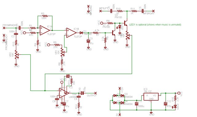
Sorry for the double post. Parts list: Qty Part Nos Description Cost/Unit Total Cost 5 c1,c2,c4,c5,c8 100N MKT Polyester capacitor $0.30 $1.50 2 c3,c7 47uF 16VW Electrolytic capacitor $0.28 $0.56 1 c6 22uF 16VW Electrolytic capacitor $0.20 $0.20 2 c10,c12 470uF 16VW Electrolytic capacitor $0.55 $1.10 1 c9 10uF 16V Tantalum $0.95 $0.95 1 c11 1000uF 16V Electrolytic $0.70 $0.70 1 d1 1N4148 Signal Diode (or similar - 1n914etc) $0.32 $0.32 4 d2,d3,d4,d5 1N4004 1A Rectifier Diode $0.40 $1.60 1 ic1 TL072 Dual Lown Noise JFET op-amp $2.35 $2.35 1 ic2 LM386N Low Voltage 1W Amplifier $2.10 $2.10 1 ic3 78L12Z 12V 100MA Voltage Regulator $1.00 $1.00 2 LED1,LED2 LED 15MCD 3mm or 5mm Some Colour $0.20 $0.40 2 Q1,Q2 PN100 General Purpose NPN (or similar) $0.25 $0.50 5 r1,r8,r10,r11,r13 1k 1/2watt 1% metal film resistor $0.38 $0.38 2 r2,r4 47k 1/2watt 1% metal film resistor $0.38 $0.38 1 r3 100k 1/2watt 1% metal film resistor $0.38 $0.38 2 r5,r6 27k 1/2watt 1% metal film resistor $0.38 $0.38 1 r7 4.7k 1/2watt 1% metal film resistor $0.38 $0.38 2 r9,r15 2.2k 1/2watt 1% metal film resistor $0.38 $0.38 1 r12 330 ohm 1/2watt 1% metal film resistor $0.38 $0.38 1 r14 10 ohm 1/2watt 1% metal film resistor $0.38 $0.38 3 vr1,vr2,vr3 10k Log Potentiomenter 16mm $1.75 $5.25 1 mp3 input 3.5mm stereo switched pcb socket $1.00 $1.00 1 radio input black 6.5mm mono phono line plug $0.85 $0.85 1 head output 6.5mm mono chassis socket - unswitched $1.35 $1.35 Total: $24.77 Based on Jaycar (http://www.jaycar.com.au) prices -
Hi All, This is a little project I was working on a while back. Its a simple audio mixer that allows input from 2 sources (i.e your aircraft's radio and an mp3 player) to be played through your headset. Audio from the primary source (normally the radio) will cause the secondary source to be muted, so any radio calls will cause the mp3 audio to go very quiet until the radio call finishes. I've pretty much ceased working on it, as I discovered the radio isn't quiet often enough to enjoy a good song. At least not on the melbourne centre frequencies. The other problem is the cost came in above what I thought is a worthwhile $maxcash level. If there is enough interest I will design a circuit board to go with this, and if there is heaps of interest I'll consider making pre-built versions available through Ian's store - assuming that he is willing. I've supplied it here in case somebody else wants to build it, or take over development of it. It comes with a couple of quick caveats which I'll give before going into further details: This has not been tested with an aircraft radio. This is simply because I don't have access to one for testing. The audio amplifier may be capable of generating enough volume to cause hearing loss if run at a high level. which is a pretty standard warning i think - basically don't crank it all the way up when your listening to your favorite tunes. I'm a beginning hobbiest - not an electronics engineer. nuff said. The schematic for the circuit is attached below. Parts list coming when i figure out how to do a table with this... The first part of the circuit is the sound activated switch based around the tl072 op amp (IC1a and b). This compares the incoming audio from the radio with a voltage level set by VR1. Once this level is passed, this causes Q1 to switch on, which causes Q2 to switch off - stopping the mp3 audio from being passed to the output amplifier (IC2 - a lm386). Once the radio audio level drops below the set level again c3 and r7 cause a small delay before allowing Q1 to switch off (and q2 back on). The vox circuit was pretty much taken straight from N1HFX's basic vox circuit (http://www.rason.org/Projects/basicvox/basicvox.htm) with just some small additions to have Q1 invert the output for Q2. The second part of the circuit is the output amp (IC2, a lm386). This is used to amplify the combined the audio inputs from the radio and the mp3 player (volume level for each is set by vr2 and vr3 respectively). Examples of this type of audio amp can be found all over the net. The final part is the voltage regulator (ic3 and associated components)- which should provide a nice clean voltage for the circuit to work with. The 4 diodes form a bridge rectifier, and is a bit of overkill, but allows the power supply to be hooked up either way around without causing any problems. The circuit should (in theory - untested) work fine off 4AA batteries (6v) if you don't want to run it from the airplane's power supply. If you want to do this, omit the voltage regulator section and connect the + side of the batteries to the vcc points on the circuit. Cost of the components comes to $24.77 based on jaycar prices. As jaycar supplies resistors in packs of 8 (for $0.38 a pack) there will be a few left over resistors at that price. Dick Smith prices may work out cheaper. The finished product should just plug in where your headset does currently, and then your headset should plug into it. Any comments would be welcome.

-
Mazda if its any consolation its probably the age, rather than the gender that was the deciding factor..
-
there is a fair bit of info on http://www.homebuiltairplanes.com/forums/ looks like your main options are welded (out due to design decision) bolted (ala the skyranger or whatever it is) or riveted.... The skyranger sounds vaguely similair to what you want to do, so it might be worthwhile checking out a few of those to see how they've done it.. buildlogs might help here. There is another aircraft which used a couple of fairly chunky ring type fittings to join the tail boom and empenage onto the body and wings.. i just don't remeber what aircraft type it was. basically (from memory) the ring dohickey went around the boom, and was rivetted to it. other aluminium tubes were then joined onto the ring as well, though i don't remeber if they were bolted or riveted. riveted seems most likely. Anyway if your custom designing something like this you may want to make use of people like http://www.emachineshop.com/ to build it for you (you design it using their cad software, send it off, they make it with their cnc machines and send it back.) wish i could remeber the name of that aircraft...
-
I havn't been keeping up with it, but isn't the Wasp still going through the prototype and certification stages (I believe its planned as a trainer)? There is a build log of a hornet up on blogspot which might be helpful: http://hornetstol.blogspot.com/
-
Thanks to all of you for coming, and I hope you had a great christmas. Sorry for the rather delayed thanks, but i've been visiting my folks, who live in a rather net deprived area (28k was the best i managed to get while there, and some of their neighbours would have killed to get that). Anyway, despite the rain, and the two lakes forming around (and in) the hanger we were in, it turned out to be a pretty good afternoon. It was nice to finally meet all you guys, though i still havn't seen Ross's cheetah in the flesh. I was feeling a little down that arvo, as I had been scheduled to fly a Nav ex in the gazelle that afternoon (fat chance). The other Ross (otherwise known about goulburn as Gyroman) took pity on me during a short break in the weather and took me up for a quick spin in one of his gyros. Holy crap those things are fun! We took off inside the length of the piano keys, and i'm not sure if the touch and gos counted (does having the tips of the grass stalks brush the wheels count as a touch?). Actually i was a little nervous about that flight, as the winds were blowing about 25ish and gusting well above 30. The gyro seemed immune to it all though, and it was much smoother than i expected. Lots of fun anyway - if you get the chance to go for a ride in one - do it!
-
Great info, thanks Tony.
-
;) Very Entertaining call. Shes a keeper though, and has been very supportive of the whole flying thing - even putting up with me keeping her awake all night doing circuits in my sleep ("goulburn traffic, ultralight gazelle 3290 turning downind for runway 26, goulburn" *rolls over* "goulburn traffic, ultralight gazelle 3290 turning base runway 26 goulburn" *rolls over* etc etc. She did object to the "touch and gos" though). Anyway, if it can't happen there will be other planes that are suitable.. she just doesnt want to go flying in an open cockpit aeroplane.
-
I've recently been looking into purchasing a Thruster TST, however my beloved girlfriend has said no to anything that doesnt have a fully enclosed cockpit. In order to resolve this I was thinking about building a set of removable (because i quite like the idea of a paritally open cockpit) aluminium and lexan doors. Does anybody know whats involved in doing this while keeping the aircraft legal to fly? Do I need to get an engineer's sign off for my plans and modifications, or can i just build it?