Bigglesworth
-
Posts
379 -
Joined
-
Last visited
Content Type
Profiles
Forums
Gallery
Downloads
Blogs
Events
Store
Aircraft
Resources
Tutorials
Articles
Classifieds
Movies
Books
Community Map
Quizzes
Videos Directory
Everything posted by Bigglesworth
-
Subject: A TEACHER SPECIAL - TOUCHING LITTLE STORY !!!! A teacher is explaining biology to her 1st grade students. "Human beings are the only animals that stutter", she says. A little girl raises her hand. "I had a kitty-cat who stuttered", she volunteered. The teacher, knowing how precious some of these stories could become, asked the girl to describe the incident. "Well", she began, "I was in the back yard with my kitty and the Rottweiler that lives next door got a running start and before we knew it, he jumped over the fence into our yard". "That must've been scary", said the teacher. "It sure was", said the little girl. "My kitty raised his back, went 'Fffff, FffffF.ffff'...and before he could say "F*ck", the Rottweiler ate him!"
-

Building "Cowboy Up", a Cheetah Kit
Bigglesworth replied to Bigglesworth's topic in Morgan Aeroworks
Good spotting.;) I hadn't chamfered it, yet. I would have spotted it later and then had to file it back until I could smooth out both sides, lucky I cut that bit off. Actually before I put the strut in, I smoothed it out with 600 wet and dry. I will admit that I didn't pay much attention to the ends since they are on the other side of the force. In my experience (not aircraft experience but close) cracks will start at the bolt and progress towards the end, not the other way. I'm glad you pointed that out, it means I have an effective quality control system in place. Also, I tried flattening the tube with various methods including in a vice, but that tended to flatten the outside edges which led to cracking. A press would need to have a small, curved head and dolly I think. Too hard to find. -
You know, that might just save my life one day. I will take it to the nearest LAME and get it done there. Actually they are only for the rudder cables so I doubt if failure would kill me, but still better if it didn't happen. Thanks
-
I have 4 Nicopress fittings on my Cheetah. I was just going to get the local marine place to crimp them for me. But you say this is not a good idea? I have the aircraft grade fittings, just no pliers.
-
I think it happened on my first GA solo. In a C150. At about 25hrs. Carb heat on on base/final, then instructor said taxi to side of runway, he got out, I went back onto the runway, did pre-take off checks (which don't include carb heat, thats run-up). Took off with full carb heat, and it was climbing horrible, would have quickly hit a hill (even at flattish Moruya). I was sort of getting worried, checked I had the speed right for climb (as a student you always think it is pilot flying error), only while thoroughly checking every gauge, instrument and control did I come across the carb heat. She started climbing then, and I started thanking God. I alway check it now before take off.
-
Building "Cowboy Up", a Cheetah Kit
Bigglesworth replied to Bigglesworth's topic in Morgan Aeroworks
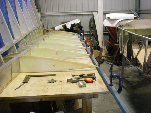
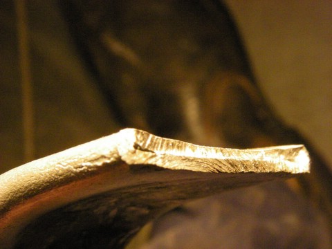
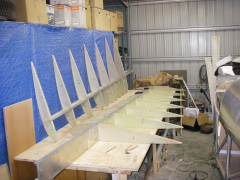
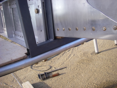
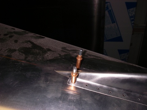
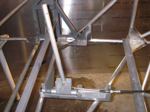
This spar is a bit of a drag I had a bit of time on Tuesday evening, so I put one drag spar in. The trailing edges of the ribs were up and down about 15mm, so I clamped them to a straight edge, (question: how hard do you think it is to find a 3+ metre straight edge). Then I straightened out the main spar and put nails either side to hold it in place (the D box will hold it later) and I roughly set up the wash out. [ATTACH]3231.vB[/ATTACH] Then I put the drag spar on top of the wing to mark it out. The original idea was to line the drag spar up with the aileron mount for a bit of extra support, but now the drag spar is kept about 1/2 inch away from the aileron mount. After all, both the spar and the mount are strong enough, and if they are together, the spar has to be at the edge of the rib, which will weaken the join. Also it would be a lot more complicated to position. So I marked out the position for the ends of the drag spar, sat it on top of the wing, and marked its lateral position. Its horizontal position was more fun. I measured off the bench to the marks on ribs 1 and 7 (last) where the holes should be, then I found the difference, divided it by 7...........etc. So I marked all the ribs purely on measurement. Then I cut out the holes with a 25mm hole saw (no room for moving the rib into position), I was confident of getting the positions right (don't know why:;)4:) But it must have been blessed, all the holes lined up perfectly, the spar slotted in nicely. And, when I took the clamps off, the trailing edge sat there in line. [ATTACH]3232.vB[/ATTACH] Of course, nothing goes that right. Where the drag spar comes out of the root rib was too high, this will mean an extra packer under it. I already had allowed one to leave room for adjustment, but now it will/might need 2. Then I started work on the drag strut (brace). It is made up of the cut off part of the drag spar. The plans show it at a pretty steep angle, but when I saw Garry's, it was a bit shallower which made sense to me. So, since there was enough material, I put the brace in at 45 degrees. The ends of the strut are bolted to the spar, and to the drag spar (and the bit of steel tube inside the drag spar at the end for extra strength). To get the bolt in, the tube ends are flattened and bent. This is harder than it sounds since the aluminium cracks if it is flattened too much. I cut the first bend off. [ATTACH]3233.vB[/ATTACH] I used a leather hammer to make these ends, since it gave the best results without damaging the pipe. I still went over the whole tube with 600 wet and dry to get rid of any scratches or hammer marks. But that's as much as I had time for, I didn't even get it bolted in. I got the slot cut in the 2nd rib for the strut, but that was easy. So there is plenty more work still awaiting me this weekend. Bring it on:). [ATTACH]3234.vB[/ATTACH]
-
Building "Cowboy Up", a Cheetah Kit
Bigglesworth replied to Bigglesworth's topic in Morgan Aeroworks
Thanks heaps for writing that in Don, it solves my problem nicely. I'm sorry to hear about your troubles and I hope all goes well, plus a speedy recovery. -
Similar, The silliest mistake in in the world Did you spot it? The two 'in's
-
While we're on the subject, Fred the flasher is getting old, he thinks of retiring soon, but he reckons he'll stick it out another year.
-
Building "Cowboy Up", a Cheetah Kit
Bigglesworth replied to Bigglesworth's topic in Morgan Aeroworks
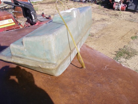
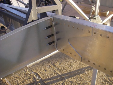
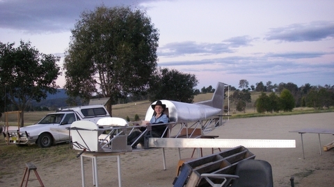
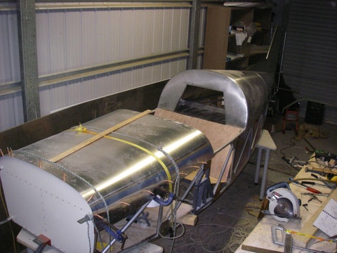
A weekend's work So the last two posts were the bulk of what I got done last weekend. I was held up a bit this weekend with my boss's birthday on Friday night, then a mate's 21st on Saturday night, which also affected me on Sunday, and Sunday morning my younger sister needed help studying for her trial exams. But I also had time to test the fuel tank for the nth time and it still leaks, not much this time but I am out of vinyl ester resin, more should get here this week. The shop in Canberra had to get it from Sydney then I have to arrange someone to pick it up in Canberra. If only building a plane was building. That fuel tank is a story of its own. It comes in 2 halves which need to be joined. Two layers of chop strand over the join to hold it together and seal it. Sounds easy. First the tank doesn't want to stay in position, but that's not too bad. Then I was too mean on the resin and the glass stayed porous in places. So I kept marking out holes and patching them until I got sick of it. So I put another layer of resin over the glass, now it still has some pin holes but at least I can see where they are. And a patch of chop strand will fix them up (I hope). So far all the holes have been in the join, so it is all my fault, as usual.:black_eye: I also got the engine mount on. When I first tried to fit it, it was that far out that I thought I must have stuffed up big time. But my work was correct to 2mm so it wasn't that. Rang Garry, and he said just pull it into shape. Apparently there is only so much he can make in the jig, and the last couple of welds pull it all over the place. So I drilled the holes in the mount, lined them up where they should sit, drilled the holes in the mount pins, put the bolts in (forced the bolts in) and tightened them up. It looks good enough, but the question is; will the motor fit on it? :;)4: Can't tell until I get rich enough to buy one. So that was my weekend. Hope yours was just as good. Now I probably won't spend much time on Cowboy Up over the week, so I will have time to respond to comments and questions. Post me what you think......
-
Building "Cowboy Up", a Cheetah Kit
Bigglesworth replied to Bigglesworth's topic in Morgan Aeroworks
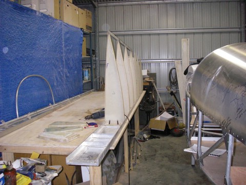
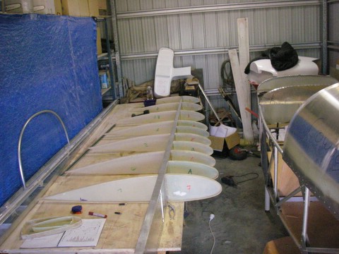
Ribbed for extra............um...........lift. While I had the spars on, I set up the root rib so I could mark out where the drag spar wants to meet the fuse. The ribs are a leading edge half and a matching trailing edge. They are positioned on each side of the spar and pop-rivetted together through the spar. I had already cleaned them up on the bench grinder sanding disc (and made a h**l of a mess in the workshop) so they were ready to work with. The position of the ribs isn't very critical, you can line them up square with the bottom of the spar, or parrallel to the fuse, or to the centreline of the spar. Or you can be like me and not be able to see any of these references while it was in position and just put it somewhere where it looks alright. As long as the bottom and top are flush with the spar. They need to be trimmed around the spar rivets, but this is just a couple of well positioned holes in each. Mounted the trailing edge rib and clecoed it on. Sat the trailing edge angle on to see where it lines up with and found it was too high. (it is meant to line up with the bottom of the fuse) The other side was too high as well so I thought "b***ger it, if it wants to sit there, who am I to say otherwise". So I lined mine up with the centre of the bottom longeron; 12.5mm higher at the back. But I figure that I'm lightweight and a smaller angle of incidence will suit me. I clamped both ribs into the position I wanted them, and then marked where they intersected with the seat angle; the drag spar sits on the seat angle. (Actually I might put the drag spar higher in the wing and put a packer on the seat angle, that way I can always drop it if I want to). Once these were marked, it was back to the bench. The other rib positions are already marked out, but since every plane is different, I remarked them, they were out by about 15mm at the worst. Actually, I had cut my spars shorter by 7mm which wouldn't help. The reason for this is that I rivetted the spars at 25mm centres starting at 25mm. Them I had to put a 50mm doubler plate at the end. Which meant the rivet was just on the edge, so I cut the spar shorter to make the holes line up. Shorter wings suit me better anyway.:) Once the ribs were marked, I put the trailing edge in first, lined them up, cut them over the rivets, and drilled the rivet holes. Then I marked where they were, took them off and lined the leading edge up with the marks and drilled them to the existing holes in the spar. Before rivetting off, I checked that all ribs sat flush with the spar, and actually had to take a few mil off most of them. Then pop rivetted them all off, and now it looks like a wing. The other side soon followed suit. Its easy once you know how:big_grin:. Another thing. The spars sit under the bend in your leg; it might be a good idea to have the spars in when the pedals are positioned, you sit a bit differently then.
-
Building "Cowboy Up", a Cheetah Kit
Bigglesworth replied to Bigglesworth's topic in Morgan Aeroworks
The seats look good, but the problem with seats is that they raise you up and then you need to raise up the top. Also at the moment the bend of your leg fits over the spar, with seats they may need to be raised above the spar which would be another 150mm at the back. Your best bet is probably to make/have made custom upholstery with extra packing in the right place, but still the the same basic shape. Maybe only raise you about 50mm which isn't too bad. Especially if you aren't tall. On the other hand, possibly you could cut off the front of the seat to fit up to the spar, and just put something thin over the spar. Also, racing seats are designed to fit snug. Good for corners, bad for hot days. But something could be done, let me know if you have any more ideas, as I might want to copy them. It could always be done later. :) -
Building "Cowboy Up", a Cheetah Kit
Bigglesworth replied to Bigglesworth's topic in Morgan Aeroworks
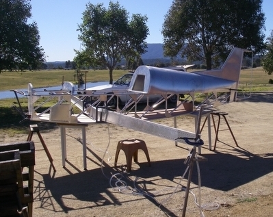
Sparring with the spars Now if I told you that it took me almost all of the day to drill 2 holes, and that there are thousands of holes to be drilled, you could do a quick calculation and say it will take me years to build this plane. However, notwithstanding that I would be telling you the truth, you would be (hopefully) way out. The 2 hole I am talking about are the 2 king pins of the wing spars. They hold the spars to the fuselage and as such are sort of very important. Setting the spars up was a job which had me practically tearing my hair out. The only thing stopping me was that I had thought in advance and protected my hair by wearing a hat;). It didn't help that I didn't understand the instructions properly and for some reason thought that I had to have the tips higher than they should be. So I started off by getting the plane outside (had to wait until the shop closed on the Saturday, customers can be a nuisance). Got the plane level, then got the spars rough in position and clamped them to a piece of wood at the tips. Then held them together with a couple of G-clamps next to where the bolts go. In the instructions it says to put a 6mm packer under the spars, and that will make them end up in the right position. I put the packer there but because of Mistake (see above sentence), the ends ended too low. So I tried lifting them up. But that meant they were only held by the clamps, and since the clamps were over both spars, I'd get one 'right', then have to loosen the clamps off for the other and all would go astray. And when I got the spars right, the fuse would be out of level. Sort of like a dog chasing its tail. And when the dog finally caught its tail (I got all set up) it looked wrong.:confused: So when trouble comes, annoy Garry. (BTW, it speaks well of the company that every time I wanted urgent information, I got through to someone who could help me straight away;)) So between me and him, and him taking a measuring tape to the demonstrator, we worked out that it should have 165mm dihedral. Thats 165mm difference between the root and tip measured on the bottom of the spar. Simple when you know. So I took down the setup I had (spilled half the water out of the levels), put the packers back, set the tips up with the clamps loose, set the other wing up to level with the first, then got checked the fuse was still level. All sits properly. Tightened the clamps, double checked everything and was ready to drill. If these holes were wrong, it meant a major stuff up. Therefore the pre-operation ceremony involved a short prayer, and for good measure, I had Mark Knopfler's Shangri La album playing. Nothing could go wrong now. Holes drilled All that fuss for 2 3/8 holes. But she looks like a plane now (surprise surprise);)
-
Building "Cowboy Up", a Cheetah Kit
Bigglesworth replied to Bigglesworth's topic in Morgan Aeroworks
The Cheetah is very flexible so how about...... Make it wider and higher (maybe start with the Sierra, more power to overcome more drag) Put a leather interior in (easy, I'm hopeing to make mine fur lined:)) Put sound proof material on the firewall (I'm going to) and around the front of the fuse. Get rid of that horrible Microair hot-mike intercom/radio and put something quiet in. And maybe X11 headsets. A new propeller should fix vibrations. Put an Enigma glass system in. (I don't like glass or I would do this) I don't know how you could fit an autopilot to it but I assume it is possible. There, what else do you want? Oh, and to make it like a Cessna, put a fuel leak in to simulate the higher fuel useage, and regularly throw some money out the window to simulate maintenance and overhauls which have to be professionally done:clown:. -
Building "Cowboy Up", a Cheetah Kit
Bigglesworth replied to Bigglesworth's topic in Morgan Aeroworks
I asked Garry about protection and he said the secret was in the metal. Don't ask me what it is (ask Garry). Its not GA grade but it is easier to work with and has good enough corrosion resistance not to need treating. Trust Garry to do something different which makes things all around easier . BTW Flyer40, Garry tells me you had a fly in the demonstrator today, what do you reckon? -
Building "Cowboy Up", a Cheetah Kit
Bigglesworth replied to Bigglesworth's topic in Morgan Aeroworks
I'm not treating the metal since it doesn't say to anywhere. I have no idea if this is normal or not since this is the first plane I have built. I once asked Garry about the corrosive properties of the aluminium and he said something about seeing it in use for many years without any corrosion, so I am hoping it will be fine without treatment. The countersunk rivets are drill sunk everywhere except on the trailing edge side of the 'D' box sheet on the wing. This has to be dimpled. Basically, wherever it doesn't need to hold much it is just drilled, and when there are high forces, dimple it. -
G'day Adam, Good to hear of other semi-locals on the site:big_grin:. My advice is get a few hours of training before you make decisions, but then, I don't know much. Just hang around Frogs Hollow any Sunday arvo, one of the locals will take you for a fly. I know, I used to do that before I got my licence. Best of luck in any case and I will probably see you around if you stay in the local aero scene.;)
-
Building "Cowboy Up", a Cheetah Kit
Bigglesworth replied to Bigglesworth's topic in Morgan Aeroworks
Up to date There, now you know where I am up to. Actually I have done lots more, but nothing major, so it will either be forgotten or covered as past details in future posts. Tomorrow night is the start of the weekend:). Work on Cowboy Up starts after my main job and continues until Sunday night. So now the posts will be real time. If you want to start adding comments, I would love to hear from you. -
Are those figures indicated or true? Because the ones I flew (timber prop) had no hope of that speed indicated, up a bit higher they would have trued it. Can't remember the RPM settings.
-
Building "Cowboy Up", a Cheetah Kit
Bigglesworth replied to Bigglesworth's topic in Morgan Aeroworks
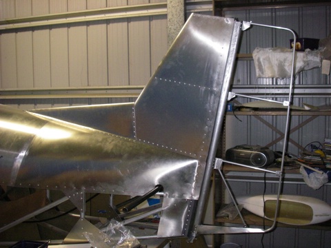
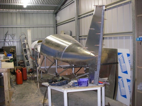
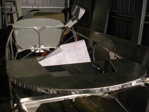
The tail of the tale, or verse vica I have mentioned what happened to the tail in the other Cheetah thread. What I didn't say was that it wasn't my fault. It doesn't matter if I say this or not because no-one believes me anyway. Basically, I took the shape off the plans and made all the measurements relative to the fin post when they should have been to vertical. So it all is sloped back 5 degrees. Might even be better, I will wait and see because I am not changeing it. To make the tail, I first found the centreline, then made the ribs out of sheet and rivetted them on. I rivetted them from the side of the tail which means the tail sheet has bumps in it. Could be better, but it will still fly. I then cut out the tail plane, making sure to measure my plane before relying on the plan. And good thing, it needs to be about another 50mm wider. So this was cut out, then the prebending. This is easiest to do free (not over a tube). I wasn't too keen about putting too much pressure on it with nothing to stop it folding, so I put one of the smaller canopy bars inside it which just sat loose and gave me peace of mind. The more pre-bending the better, so I tried to keep going until it sat perfect. But it was not to be. I put a 2x4 over it, stood on it, JUMPED on it, held onto something heavy and jumped on it, stood on it and pulled myself down. But it was all for not enough. At ~72kg I am simply not fat enough:;)1:. I need to eat more. But for now the tail is good enough. I put it on, rough marked the base, cut that, then marked it again, cut it again, etc. etc. For about 4 hours. And it still isn't quite perfectly scribed. Later Garry tells me that you just put No More Gaps in the holes and don't bother being fussy. Its easy once you know. It is the sheet which holds the tail straight, so line it up good before rivetting. The forward fin looks easy. The bend I did tighter than the tail, so that the join would be better. At the front I stopped the 'legs' about 40mm from the apex which made a neater finish with the top bend in a straight line. I didn't work out exactly as I planned but No More Gaps will fix it. The forward fin is rivetted to the fuse (at 3 inch centres I later found out. After I had done 1 inch;)) and also to the tail. I drilled and clecoed it to the fuse, and then drilled the holes to fix to the fin. Still wasn't smart enough. When I rivetted it down, the rivets pulled harder than the clecoes, and all the holes into the fin were out by about 1mm. Ran the drill through them and hope they expand to fill the gaps. The rudder is also drawn the wrong shape in the plans. The top, same deal as for the fin, and the bottom, the rear corner is 100mm up fron the extended bottom longeron. Not, as I made it, from a right angle. Still, it looks alright, and Garry says he has never known his to 'sit down' on the tail, so I should be alright. The rudder post needs to be tapered, I did this with a leather hammer, I think it will look smooth when it is covered, if not, it might need a bit of fill, but I doubt it. The top nylon block fitted in easy enough. Only, I had a lot of lap on the fin sheet, so I wanted to keep the rudder back, I almost did it too far, the hole is borderline for edge thickness. But being nylon, the bolt will wear down first anyway.:) Also, to even things out, I put the bottom end too close to the fuse and almost had to cut too much out for the stops. Again just borderline.
-
VA 80? Can it actually go this fast at a constant height? I remember when I was learning to fly in one, we had 60-65 cruise. And it didn't get much better.
-
Building "Cowboy Up", a Cheetah Kit
Bigglesworth replied to Bigglesworth's topic in Morgan Aeroworks
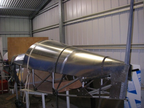
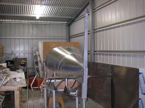
Decking my plane If you are like me and have never done much with sheet metal before, you will understand when I say I was very scared of this phase of building. So much metal, so critical and so easy to get wrong. And my luck seems to be out to beat Murphy's; "even if its not possible for something to go wrong, something will go wrong". As it was I needn't have worried overmuch. It was reasonable once I knew what I was doing. I started this job by annoying Garry by ringing him and getting his personal opinion on how it should be done and why the dimensions are wrong on the plan and what should be done about it. So, basically the turtle (rear deck) was first, it looks harder, but because of that, it is easier. I started by making up the material for it by joining 2 sheets together and cutting out the right shape. The correct dimensions are: Front, the circumference of the bulkhead plus lap, Rear, 440mm (from plan, includes overlap), length, measure it, allow 15mm for cover at the rear, 10 for having to trim the front because I'm an idiot and it didn't sit square, and a bit more to cut off later, just for fun (thats rec. flying isn't it? just for fun?;)). I had a mate to help me cut out the basic shape, so with his help we had to get it wrong. It was my fault really, but don't tell him that. See, I rough cut the section off the main sheet. Which meant that I didn't have a factory edge to measure from for the centreline. And believe me, a set square is ineffective above 1 metre. In any case thats how we did it, then rivetted the sheets together (countersunk rivets, I used them in most places. They are not meant to be used so I will need to buy extra, Garry just wanted to save time for builders, but I want mine pretty). Later when I went to put the deck on, it didn't line up at the front bulkhead. Oh dear. Just where I wanted a nice factory edge. I got it rough in position, marked the 2 sides of the bulkhead, took the sheet off, scored it with a Stanley knife, then pulled the strip off. Nice and neat. The back end of the sheet has to be pre bent. this isn't hard, but it looks really awful and I was certain I'd regret putting creases in my nice shiny sheet. As usual with anything I'm certain of, I was wrong. I tied ropes over the top to hold it down and G-clamped it to the longerons before rivetting it off. Only later I noticed that the front has the right lap (25mmm) but the back is supposed to have excess lap and the top should be at the specific height of "just above the elevator horn". So mine is high about 50mm. Big deal. The front deck is only held to the front bulkhead, the rear one is just to give it shape and to fall over when I was trying to pull the sheet on top of it. In the end I cut out a template to hold it in shape and that still didn't work all that well. But I figured 'the rear bulkhead is only meant to be siliconed on, silicone fills large gaps'. So I drilled and clecoed it off, then marked the front cutout for the cabin. Took the sheet off, cut out the cabin, cleaned up the sheet, put it back on and Hey Presto!, it fits perfect. Don't ask me where that gap in the middle went, maybe it was needed in another life and that suits me. I haven't rivetted off the front, I still need to get in to get to the fuel tank (another story) and things like that. So now it is clecoed and I have no more 1/8 clecos for use in other places. Remember: Even if you have enough clecos, BUY MORE CLECOS. You never know what they might be handy for.:confused: On a side note, Clecos are totally unknown outside aviation. If you have any friends who thing they know about metalwork, talk to them about clecoes, they will be suitably squashed. Believe me, I've done it. Anyway, now my plane has better curves than ***** ***;).
-
Building "Cowboy Up", a Cheetah Kit
Bigglesworth replied to Bigglesworth's topic in Morgan Aeroworks
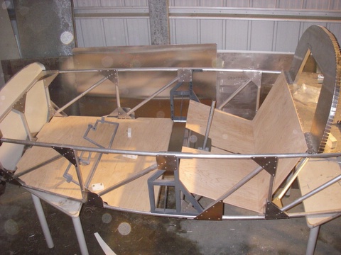
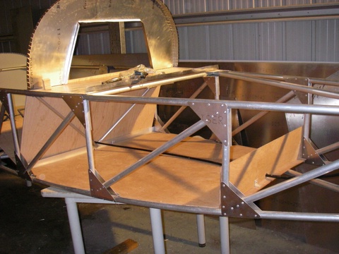
....... In The Woods The woodwork was next. That is the floor, seats and the cargo bay. The floor and seats are supplied but the cargo bay is optional extra since everyone has their own idea of what it should look like. Like me needing it big enough to fit in my guitar, and/or my swag and a gun rack. So basically it is purty easy. First cut out the basic shapes, the lay them under the fuse, trace around them, mark where the gussets and uprights are, mark around these and cut. Using my carpenter's skills I got it down to almost perfect. Of course we couldn't have that, there was no way I could get it into position. So I had to take a bit off certain areas, all cutouts were made 45 degrees and then, with a lot of bending, it fitted in. Of course then, I couldn't get it out. So when I went to fit the rudder pedals, it needed a really short screwdriver (bit in a ratchet) to get some of the screws on. Watch those pedals, the nylon blocks are a bit too tight. Before you put them on, trial fit them to the pedals, they should be firm but not too tight. When I fitted them the first time, it was hard just to move them, wouldn't have needed rudder trim, pedals will stick anywhere you leave them;). So I had to pull it all off, file them out, and put them back on. Also remember to lubricate the shafts with vaseline or similar. Only when you are happy with the pedals should you rivet off the floor. When positioning the pedals, sit in it and find where they would be comfortable. And remember to take in account the seat upholstery; you can always put foam behind you, but it is hard to move the seat back. With the seat, don't be too fussy as yet. I was, got it nice and neat, then I had to cut out more for the trim tab, and will need still more for the drag spar and the seat belts. Waste of time getting it nice now. [attach]IMGP1067[/attach] [attach]IMGP1068[/attach] The seats are held in at the front by a screw each which is threaded into the steel frame. I paid a bit of extra attention here and got the screw hole right on the edge of the frame. This means it will hold down evenly and look neater too. It is not necessary to be this fussy, but, thats me. The cargo bay is choose your own adventure. Nothing is supplied for it. So first of all was a visit to the hardware, and believe me, after working with the quality wood that is supplied for the floor, all the common types of wood weigh an incredible amount. I eventually settled on a 3 ply for the bay since was the lightest they had. When I compared it th the seat, I found that the 3 ply was almost the same weight and nothing near the strength. But most likely only a fraction of the price. I decided not to bother trying to get the good quality wood and just use the the cheap stuff. For now anyway. Lucky I did too, because I would have had no chance of getting the stiffer wood in place. I extended the cargo bay 1 section further than Garry, and to make up for the extra weight, I only put a small back on it. Now it fits a guitar, and longer things can be extended over the back provided; a, they are lightweight, b, they don't foul up the elevator gear (that leads to a small case of death).:black_eye: [attach]IMGP0993[/attach] So that was the easy part done
-
Building "Cowboy Up", a Cheetah Kit
Bigglesworth replied to Bigglesworth's topic in Morgan Aeroworks
If it is to be a tie, you will have to work just as hard as me (or are you a lot quicker worker than me, probably). Are you prepared to work 9am-1am without longer than 1/2 hour for meals and other breaks?;) That includes checking my email accounts and replying to any comments on this forum. Maybe you just get to work during the week, that leaves all my effort for nothing . How's progress going on yours? I still haven't got around to doing a photoshop (or in my case GIMP) of my colourscheme, it would take me too long. And image manipulation is hard with only the touchpad mouse on my laptop. I take my laptop to the workshop and then can look at all the photos of Garry's plane to copy from. The problem is that Garry did a lot different (small things) from what the kit is.:confused: {Note to all readers: Anyone who builds a kit should take a camera with them to the factory and photograph everything that is being build at that time, it is really helpful} Keep working hard, And feel free to post images of yours in my thread; you never can have too may pictures of these beautiful planes;). -
Building "Cowboy Up", a Cheetah Kit
Bigglesworth replied to Bigglesworth's topic in Morgan Aeroworks
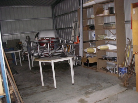
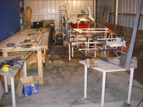
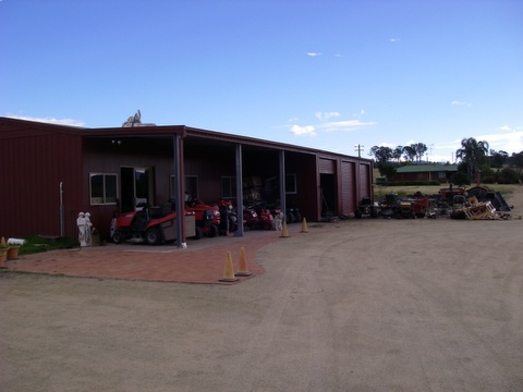
The workshop and what goes on inside it When you set out to build a kit aircraft, one of the main things is where will you have the space to build it. Garry built his in a single garage, but since it was full of tools, he had to work partly outside and I didn't like this idea. Might be alright during the day but when I'm working up until the wee hours of the morning ( only routine work [e.g. sanding] at that time of night, otherwise major mistakes are made), I want to be able to keep everything under roof, and closed off from the frost outside. Luckily my boss (where I work as a small-engines mechanic) is a good bloke and he offered to let me use the last bay of the workshop. He even cleaned out all the dead motors for me. And got an electrician to put lights in.;) No heater though:sad:. So, waiting for me when I got home was an almost empty single bay, slightly longer than normal, which I could use exclusively for building in. All the tools I might need were in the workshop next door so I didn't need the clutter of tool storage, just the ones I was using at the moment (and, me being me, for the last week or so. I never seem to get around to clean up:;)1:). So first I needed to equip it with a work bench. I made mine 1200x4000, and I'm glad I did. It means I have less floor space, but I can fit a full sheet on it which is very handy, and it has to be long enough to hold a full wing when I get that far. We also made sure that the customers couldn't see the last bay, too many question take up too much time . Then all I needed was a couple of small benches or trestles to sit the fuse on. And all was set. I also had to unroll the sheet metal........... BE VERY CAREFUL WHEN DOING THIS. I had an empty patch of floor long enough, and there was me and my boss holding it; all should have been alright. But.......his mutt of a dog decided to get in the way, and we both reached out to get it out of the way at the same time, and SNAP ~ there went the metal. All would have been well it we had been unrolling straight, but life isn't like that. One side landed on a water pump............ Total damage: one crunched corner where it hit, plus 2 sheets with 200mm creases in the middle of them. OUCH :black_eye:. One sheet I was able to cut around the crease, with the other one, I put the damaged bit in the middle of the fold in the tail. After folding it, there is no more sign of the crease ;). While on the subject of sheet metal: when I got home I didn't want to cut anything until I was sure of what I was doing so I kept looking at the cutting guide and the sheets I had left with increasing worry. You guessed it; I had cut way too much off for gussets. This is not clear in the guide since it has the cutting list for the single seater and then says what to do differently, but it is not very clear. So do your calculations BEFORE you cut. I can tell you now that you can take 500 off the 3rd 25thou sheet (1&2 are for the wings), then another 500 off one of the wing sheets, the other uses the end for the parcel shelf. Then if you are still short, there is cutoff from the edge of the wing sheets, that will work better than what I did. So, basically I needed another 4 pieces of 600x600. Not too much of a cost, but freight might be a problem. Not to worry; I was going to get a bit more anyway and sheet the inside of the fuselage, it looks better that way. I will get the sheets when I need them which is still a way to go. I might stuff up more and need another sheet on top of that;). Basically the first few days I spent on the plane by myself, I wasn't game to do anything major, just put on more gussets and cut out what was marked, like the rear bulkhead and the firewall. Was good to get the firewall on, it held the front square, I have got the diagonals correct to 2mm which should be good enough. The rear bulkhead I made slightly larger to the side of the head. When I was in the demonstrator, it was there that I was hitting. The Sierra uses a larger all round bulkhead and Garry offered to make me a tracing of this but I didn't want to add too much drag. I only increased it by about 7mm at the maximum point. I also got joystick made, (it only needs a couple of holes drilled [the hard one is already done] and the stops cut to depth) and then could mount the elevator cable. I was also spending a lot of time tinkering with bits and pieces trying to understand it a bit better. And writing emails to Garry with questions, comments and complaints. He must already be getting sick of me, but he has always helped me out to the best of his ability. More power to him.