Dafydd Llewellyn
-
Posts
1,513 -
Joined
-
Last visited
-
Days Won
43
Content Type
Profiles
Forums
Gallery
Downloads
Blogs
Events
Store
Aircraft
Resources
Tutorials
Articles
Classifieds
Movies
Books
Community Map
Quizzes
Videos Directory
Everything posted by Dafydd Llewellyn
-

"Jaberoo" down (Mildura this time)
Dafydd Llewellyn replied to a topic in Aircraft Incidents and Accidents
Yes, you're dead right. The difference is what we urgently need to discover. Ian Bent is working on a "better" engine; but there's still obviously something out there that affects engines quite separately to any marginal design. So far we have two contenders - lead fouling causing valve sticking marginally open; and changes in mixture distribution due to (a) Carburettor being re-installed slightly tilted; (b) Change in airflow "swirl" due to minor changes in the induction duct geometry (I've seen some very distorted airbox outlets) - and, possibly but far from proven, air leak into one of the manifold joints at the point where the distribution tubes connect to the plenum. Keep the reports coming in, please. -
"Jaberoo" down (Mildura this time)
Dafydd Llewellyn replied to a topic in Aircraft Incidents and Accidents
It's a fair question; and liquid cooling can indeed make it easier to get uniform cooling. However, ultimately the heat rejected by the engine has to be carried away by the air; and shifting heat from A to B requires that B must be cooler than A - as Flanders & Swan put it: "Heat won't flow from a cooler to a hotter; you can try it if you like, but you're far better notter". (Second law of thermodynamics). A liquid-cooled engine has to shift the heat three times - firstly, from the engine metal to the coolant; and then from the coolant to the radiator metal; and then from the radiator metal to the air; so it has to divide the available temperature difference into three parts. So it's not that easy to achieve overall cooler engine running that way. In fact, most liquid-cooling systems use pressurisation and glycol to allow the engine temperature to be raised, in order to increase the available temperature difference. Secondly, a liquid-cooling system significantly increases the potential failure modes; air cooling is much more defensible in court. Given the way the American product-liability situation affected aircraft manufacturers there in the 1980s, I doubt any American aircraft engine manufacturer would dare build a liquid-cooled engine. Rotax originally tried both air-cooled and liquid-cooled versions of the 912; I saw both prototypes in their development shop in 1985. They finally chose the liquid-cooled heads because it was primarily a motor-glider engine, and glider pilots cannot be relied upon to cool the engine gradually before shutting it down. The choice has worked for them, but it makes the engine very messy to install. Thirdly, liquid-cooled heads tend to be prone to local boiling, which can result in the steam "blowing" the water out of the head - which then "cooks" in seconds. This has been a problem in several of the later Peugeots that we have had, so car engines are by no means immune to this. It helps if the heads are at the lowest point in the cooling system, which makes me wonder why we do not have inverted V-layout aircraft engines; a de-gassing bottle is a real necessity, and Rotax provide one for the 582. Finally, research was done back in the 1920s and 1930s - I think by H Roxbee-Cox, at RAE, which showed, surprisingly, that the exhaust valve temperatures of air-cooled and liquid cooled cylinders were pretty much the same. That was with the cylinders available at that time, but most of the fundamental research into aircraft piston engines was being done then; after about 1940 the research was into jets, and has been ever since. -
"Jaberoo" down (Mildura this time)
Dafydd Llewellyn replied to a topic in Aircraft Incidents and Accidents
Thanks again. The test schedule required by certification standards such as JAR 22 and FAR 33 is what the applicant is required to do, and as you say, it does not address the lower-power operations that occur in actual service very well. The aircraft's certification flight testing generally requires about 25 hours of flying if all goes well; but test pilots do not tend to muck about on the ground; once I'm comfortable with the powerplant, I usually do my engine checks whilst taxiing to avoid picking-up gravel; so the engine does not get exposed to the sort of delays one finds at a busy airfield. I'm not sure what can be done in the engine design area to reduce this problem (if indeed anything can be done); the issue with AVGAS is that, unlike the old leaded "Super" car fuel, the TEL mixture does not contain an excess of bromide to clean up the lead despite the variable running conditions in a motor vehicle (it used to contain 2 to 3 times the chemical equivalent of the lead), AVGAS is only permitted to contain the precise chemical equivalent of the lead. I used to use a mixture of Super and AVGAS in my PA 28 for this reason, and it did keep the plugs clean and the valves from sticking - but one cannot do that nowadays, because only 100LL still contains lead, and no fuel to my knowledge contains excess bromine. There's a product - a fuel additive - called "Decalin" - that is supposed to help remove lead deposits from valves; I've not tried it; I wonder does anybody have any experience with it? -
"Jaberoo" down (Mildura this time)
Dafydd Llewellyn replied to a topic in Aircraft Incidents and Accidents
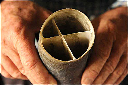
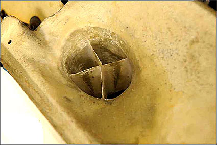
Here's what Ian McPhee did to improve the mixture distribution in his Jabiru-engined motorfalke; the first attachment shows the upper end of the "cobra-head" duct that was necessary for that installation; the second shows the outlet from the carburettor air selector / filter box. The purpose of these is to de-swirl the air entering the carburettor. The fuel spray leaving the carburettor is deflected up or down by the position of the throttle butterfly; and if the airflow is swirling as it passes through the carburettor, the fuel spray will be deflected sideways as well. That will cause a mixture mal-distribution in the plenum. The swirl is likely to be generated in the airbox, and it will intensify, like water going down a plughole, as it flows into the airbox outlet. Anything of this sort must be located downstream of the hot-air selector, or it will present an induction ice hazard.
-
"Jaberoo" down (Mildura this time)
Dafydd Llewellyn replied to a topic in Aircraft Incidents and Accidents
Thanks; that's most interesting. To my understanding, lead fouling occurs when the engine is running too cool for the bromine in the TEL mixture to react with the lead, forming lead bromide, which is carried away by the exhaust. It was a well-known issue with Lycomings etc used for training, especially on 100/130 AVGAS, but in the spark plugs usually. Didn't get it much when cruising at lean mixture. Were you doing a lot of idling on the ground, or other low-power operation? Also, which cylinder was it? -
Chasing better spelling...
Dafydd Llewellyn replied to Old Koreelah's topic in AUS/NZ General Discussion
"Include me out" is a quotation from, I think, Sam Goldwyn. -
Chasing better spelling...
Dafydd Llewellyn replied to Old Koreelah's topic in AUS/NZ General Discussion
When Andre Turcat, the chief test pilot on the French side, gave a speech in America (in the 1960s) about the Concorde, he opened by saying, "ladies and gentlemen, to-night I will be speaking in English, which is neither of our languages . . . -
"Jaberoo" down (Mildura this time)
Dafydd Llewellyn replied to a topic in Aircraft Incidents and Accidents
That's not what the statistics - such as they are - show (assuming - as I do - that valve failures are likely to be related to cooling, due to a thermal runaway effect; not all of them will be, of course. Turbs has a different view). -
In any Lycoming ( and as far as I know, Continental - tho I'm less familiar with them) that has been in operation for a lot of years, but low engine hours, get a LAME to remove the front welsh plug from the crankshaft and inspect the inside of the front end of the crankshaft for corrosion. Also, I suspect parts are getting difficult to find for early o-200 s.
-
"Jaberoo" down (Mildura this time)
Dafydd Llewellyn replied to a topic in Aircraft Incidents and Accidents
I should perhaps qualify that, by pointing out that there are two separate aspects here; the first one is to qualify the mod. package that constitutes the CAMit-modified engine. An undercylinder baffle may well be a mandatory part of that, if it works. How the air gets delivered to the engine and the oil cooler, is not part of the engine; it's part of the airframe. So precisely where the engine stops and the airframe begins is not as yet determined, for the CAMit package. Modifying the airframe part of that would involve an STC for each airframe model; and of course that cannot apply to the models built under LSA. So that side of the question is a separate program; and it has second place to getting the engine package done. -
"Jaberoo" down (Mildura this time)
Dafydd Llewellyn replied to a topic in Aircraft Incidents and Accidents
I don't know, for the original certification work. They certainly will be, this time. We're looking quite hard at improving the baffling under the cylinder barrels. Ian Bent has been most recently researching exactly this point. Re an air dam cooling setup, I can't delve into that in the test cell, it has to be done in flight. But the whole cooling system is under review in this program. I've no idea at this stage where that will take us. -
"Jaberoo" down (Mildura this time)
Dafydd Llewellyn replied to a topic in Aircraft Incidents and Accidents
Turbs, I'm not quoting Continental and Lycoming to water down people's concern; but their prior experience is valid engineering history. And yes, the number may well be considerably higher than 4% - but it doesn't affect my point where it's 4%, 14% or 44%; when you get a problem on one cylinder and not on the rest of them; or on a minority of the engines in service, then you have to look to why the difference. Now, candidly, I'm fed up to the back teeth with this thread; I have work to do. -
"Jaberoo" down (Mildura this time)
Dafydd Llewellyn replied to a topic in Aircraft Incidents and Accidents
Yes, but why on one cylinder only? And if it were that simple, how come there are only 12 occurrences in five years? Continental started with phosphor-bronze guides, went through cast iron and sintered steel, and finally ended-up (at the last time I looked) with phosphor-bronze again. Go figure . . . -
"Jaberoo" down (Mildura this time)
Dafydd Llewellyn replied to a topic in Aircraft Incidents and Accidents
Good question. Next question? -
"Jaberoo" down (Mildura this time)
Dafydd Llewellyn replied to a topic in Aircraft Incidents and Accidents
Yep, and if you have airflow rotation ("twisting") through the carbie, the fuel spray will not be what the plenum was designed for. If you can figure how to design a plenum chamber that can tolerate that, I'd dearly like to know about it. The updraft manifold-in-sump used on most of the carburetted Lycomings looks as though it should be much better, but the Lycoming data on leaning techniques using EGT shows that it is not. What squish chamber are you referring to? -
"Jaberoo" down (Mildura this time)
Dafydd Llewellyn replied to a topic in Aircraft Incidents and Accidents
Oh, certainly one needs to get to the root of the problem - and the cause of serious thermal runaway in one cylinder is almost certain to be something remote from the airflow through the fins etc. The relevance of the test-cell cooling system is that it has to satisfy the engine type certification endurance test requirements, which means it has to be able to hold all the cylinders on the engine at or slightly above the red-line temperature limit stated in the TCDS, within fine limits (about 2 degrees C), throughout the specified endurance-run duration. So that's a very specific design issue that has no direct correlation to how engines are used in the field. In the process, it may provide some useful information on such things as the cylinder baffling, and the pressure drop needed to adequately cool the engine at its rated power condition. What the test-cell work can establish is that the engine, if it starts the process in good condition, can withstand operating at the limits for a sufficient length of time to show that no run-away condition occurs in the short term; and that its condition as shown by the strip inspection after the test run, is such that it could be reassembled and go back into service with no repair or replacement. The condition at the end of the endurance run should show that the endurance merely served to "run it in" a bit. I have always considered it a bit simplistic to demonstrate that the engine can survive X degrees for 50 hours, and then project that to suggest that it's OK to operate at that temperature for 2000 hours - but that's the way the Type Certification requirement works; the red line temperatures are what is demonstrated in the test cell for more than half the run duration. The manufacturers generally give a reduced "recommended" temperature limit for best engine life, but that is really something that needs to be found from operational experience; there's no other way to establish it. And of course it needs to take into account the likely errors in the instrumentation, in the field. What we're seeing in these 4% or so of failures, is either that the operating conditions can go outside the certificated limits and produce a failure; or that operating close to the limits for a long time will cause trouble, or that exceeding the limits for even a very short time can start a failure process that has a cumulative effect. The data show only the result, not the cause. The cause is often quite indirect and also complex. And whilst close monitoring of the CHT and EGT of all cylinders is all one can do as an operator to get warning of out-of-limit conditions or impending trouble, that does not necessarily mean that "fiddling with fins and ducting'' will prevent such occurrences. What we DO know, is that thermal runaway will occur if the operating temperatures get too high; and there are a number of ways that can happen. The most obvious one is detonation, but valve guide wear and carbon build-up in the ring grooves are also examples of thermal run-away issues. So the basic operating temperatures ARE relevant, and reducing them is the major way to improve overall reliability. Philosophically, the question of whether the engine is good enough for the consumer, could equally well be turned around - is the consumer good enough for the engine? Evidently, from the data, most of them are. (Apologies - couldn't resist that). -
"Jaberoo" down (Mildura this time)
Dafydd Llewellyn replied to a topic in Aircraft Incidents and Accidents
Normal motor vehicle production, you mean I think. They're large-volume products. Aero-engines are not. Bombardier can afford that kind of thing, but a small Australian manufacturer cannot; and even then, as you point out, the demograph of users cannot be reliably tested for in a laboratory. The critical temperature with the guide is NOT necessarily its melting point. If you have ever done any study of metallurgy, you would be aware that metals are, in general, complex solid solutions of the various alloying components, often with some elements precipitating out of solution in the form of minute particles, and that metallurgical changes often occur well below the melting point. The tempering process for steel demonstrates that; and some aluminium alloys start to lose strength at as little as around 120 C (the rate of strength loss is very slow at the start, but it increases with increasing temperature) - the top speed of Concorde was set by this. I don't know what goes on in phosphor bronze, but one of the reasons it it so universally used in valve guides is that it "grows" in use so that it takes up the wear, to a certain degree. Have you never experienced a bronze bushing that has seized on its shaft due to lack of use? That process evidently ceases to work beyond a certain temperature, and the natural lubricity of the stuff ceases to exist - for all I know, it may be a change in the nature of the natural oxide film on the surface of the metal. Have you never seen a turbocharger bearing heat shield (the bit that looks like a miniature brake drum, tho it does not rotate, and is there to keep the bearings from being cooked) that has warped so much that it has worn a groove into the back of the turbine? Do you know how this warpage occurs? It's NOT due to melting; metals are not that simple. So the CHT is most definitely relevant. If we could measure the valve guide temperature reliably, that would probably be even more relevant, but CHT is what we can measure - if we're careful. -
"Jaberoo" down (Mildura this time)
Dafydd Llewellyn replied to a topic in Aircraft Incidents and Accidents
Hmmm; there's an awful lot there; let me see if I can address some of those points: Firstly, the exhaust valve issue: From what I have seen of this (which isn't a lot, so far), the problem in the Jab occurs when the exhaust valve guide temperature exceeds some limit - and it's phosphor bronze, not steel, so the temperature will be a lot lower than what you see by putting an oxy torch onto a valve. When that occurs, the guide wears very rapidly (This is not confined to Jabiru engines, BTW, Continentals especially seem to operate very close to this temperature limit, and valve guide extreme wear is not as rare as one would like). They are fine at some power rating, but increase that only a few percent and Bingo! Continental made it their policy to get a few more horsepower per cubic inch than Lycoming, to add to their market appeal, and this sort of problem has been the result. The guide wear does two things: Firstly, it reduces the ability of the valve to shed its heat via the valve guide, so the valve temperature increases rapidly. This accelerates the guide wear problem, so the process becomes a "run away" one that accelerates in a short time. Secondly, the increased clearance means that the valve starts to impact its seat off-centre, which causes bending loads on the now overheated valve stem. This produces a fatigue failure in the valve stem. There is also some evidence (Ian Bent found this) that even a minor increase in valve temperature due to the early stages of this process, causes a form of pitting erosion on the neck of the valve stem, which itself acts as a fatigue-crack initiator. Also, an overheated exhaust valve head can initiate detonation. Ian Bent's experiments with his own 3300 have demonstrated these factors, tho because he's doing in-flight experimentation, he's pulling the engine down before he suffers a catastrophic failure. Detonation radically increases the exhaust-gas temperature, so adding to the catastrophic result. All of this means that the ability of the guide to lose heat in its turn, is critical; and the CHT is a major aspect of that, because the rate of heat flow out of the guide depends upon the head metal into which it is pressed, being sufficiently cooler; the "thermal gradient" between the guide and the head must be sufficiently steep for the heat to slide "downhill" fast enough. The head-metal temperature will also affect the temperature of the oil in the rocker box, and hence its ability to do its part in cooling the guide. So the whole process goes "over the edge" at a CHT temperature that is way below the temperature that the valve metal starts to soften. The oxy-torch analogy really isn't relevant. What causes the high head temperature in the first place? Well, obviously mixture mal-distribution is likely to be a prime factor - and because that can be affected by so many things, it's difficult to manage in a multi-cylinder engine with a single carburettor. One of the unexpected causes of it is swirl in the airflow entering the carburettor; this was spotted by Ian McPhee in the work-up of a Jab 2200 installation in a Motorfalke, though I expect it's a problem that has been around as long as the internal combustion engine, but it was a new one to me. That's an engine installation issue that is a bit too subtle for the normal type-certification tests to pick up. That is one of the things that a multi-point fuel injection can fix, but it brings with it its own set of problems; and right now I'm trying to answer Turbs's questions. Mal-distribution of the cooling air supply is, obviously, another potential cause. So it follows that monitoring both the CHT and the EGT is a prudent thing to do. In regard to the engine RPM issue: The fundamental fact of life with an aero engine is the propeller tip speed. Propellers become very inefficient if their blades start to generate shock waves, which can start to happen well below the speed of sound, due to the accelerated local flow on the blade aerofoil involved in generating thrust. More lately, this has been exacerbated by more demanding aircraft noise limits. In practice, this means the propeller tip speed cannot go much above about 750 feet per second (230 metres/second). There is also an overall increase in propeller efficiency, especially at low flight speeds, from larger diameters, and the larger the diameter, the lower the RPM must be to stay within the tip speed limit. As a consequence of this, aero engines fall into two distinct categories - geared, and direct-drive. The Rotax series exemplify the first type; the Jabiru, the second. Geared engines in the past, such as the Lycoming GSIO-480 and GTIO-540, and the Continental geared 520 series, have not been particularly reliable, because in an aero engine, the propeller has to act as the flywheel. Therefore, there are large oscillatory torque pulses being exchanged between the engine and the propeller, which give the gear teeth a very hard time. So the more reliable and durable GA engines have mainly been the direct-drive Lycomings, which run at 2700 RPM or less. Continental, in their drive to be seen as having a higher power to weight than Lycoming, went to 2850 RPM with their direct-drive 520 series - which is why a Beech Bonanza make such a loud noise at takeoff. It would not pass current noise certification standards. Direct-drive engines are limited to relatively low powers - above about 300 horsepower, the limited propeller diameters become too inefficient, so gearboxes become necessary - and engine overhaul costs increase accordingly. So a direct-drive aero engine has a lot in common with a tractor engine, except in the use of cast iron. Rotax has gone the other way, and they have managed to make it work - for very limited propeller moment of inertia, by using a spring-element between the engine and the propeller. The gearbox tooth loads on the tiny pinions used in the higher-ratio reduction boxes are rather terrifying; it seems an example of pushing gear technology to its limits. As the engine go up in power, the gearboxes generally have to become vastly more complex, to share the loads between a number of sets of teeth; and the engines get a lot more cylinders, which reduces the magnitude of the torque pulsations. At high RPM, the inertia forces become dominant; at low RPM, the gas pressure loads and the connecting-rod angle become the dominating factor. Horizontally-opposed engines are always at the very limit of connecting rod angle, and extremely "oversquare" because this is the only way to keep the engine width within reasonable bounds. The Rotax gets away with it because of its small capacity; it is using the square-cube law backwards, as it were; but this concept has little potential to be scaled up. A vee engine is inherently compact, without needing to go to extremes of either bore/stroke ratio or connecting-rod angle. A 90 degree V engine also has good inertial balance; but until you get to eight cylinders, it has uneven firing intervals. A V-8 layout like the Chev, is in many ways ideal, but scaling it down to an 80 HP aero-engine would be far too costly. As a result, you can't really compare a Chev racing engine with an 80 ~ 100 HP aero engine; the factors that drive the design are too different. The through-bolt issue has at least six facets, which Ian Bent can explain much better than I can - and he did so at Temora. They are all subtle aspects of detail design, and assembly technique. The peak gas pressure in a Jab engine is not that much different to that in the Holden engine from which its pistons come; but the details that dictate the retention of the bolt pre-load are radically different, because the engine has to be so much lighter. I won't attempt to pass on second-hand information; if you want to know more about this aspect, Ian Bent has the answers; but please remember that he's flat out trying to get his mod. package out. -
"Jaberoo" down (Mildura this time)
Dafydd Llewellyn replied to a topic in Aircraft Incidents and Accidents
Remember the Airbus A 320 debut at Paris, where the fly-by-wire overruled the pilot? Yes, the French seem to have by now got most of the bugs out of the software. But if you look at the certification requirements for software, it will become very obvious why we are not likely to see that sort of autonomy in systems for toy aeroplanes; the cost of the proof-of-compliance for the software would put the cost of the product up by a factor that no manufacture could be competetive with. You all accepted the el-cheapo altimeters and airspeed indicators, didn't you? So are you going to accept el-cheapo automated flight hardware? It's coming, in the form of being able to input a flight plan into a moving-map GPS and simply press the go-to button; but remember the issue with the autopilot trying to maintain height in the MU-2? The EMIS (if you want to call it that) is an iterative step that is currently acceptable, provided it has a TSO. -
"Jaberoo" down (Mildura this time)
Dafydd Llewellyn replied to a topic in Aircraft Incidents and Accidents
No, I would not argue that. As I said, there is a real point in what Ian Bent is doing. The dilemma was very well expressed by an airline pilot friend of mine, who was confronted with the choice between the Boeing 737 and the A 320; he said: "Fly -by-wire is OK with me, as long as the wire is 7 x 19 . . ." -
"Jaberoo" down (Mildura this time)
Dafydd Llewellyn replied to a topic in Aircraft Incidents and Accidents
Yes, well I was using the manufacturers' terminology. In aviation, we've tended to give the PIC the ability to make his own decisions. Admittedly, using the Bing CD carburettor has eliminated one of them - the ability to mis-manage the mixture. Now, if we could come up with something as simple and reliable as the CD carbie to eliminate the pilot's ability to mis-manage the carby heat . . . There is a well-known intellectual conflict between pilots and designers over this; the pilots want to be able to control the damn thing; the designers - especially the ones who are not themselves pilots - want to remove as much decision-making as possible, so the pilot doesn't get it wrong. As both an engineer and a pilot, I find myself wanting the control, in the aircraft that I fly, but wanting to automate it as much as possible, in an aircraft that I allowed you silly buggers to fly . . . -
"Jaberoo" down (Mildura this time)
Dafydd Llewellyn replied to a topic in Aircraft Incidents and Accidents
That's the fundamental difference between a pilot and a zombie. Me, too. Being able to record the history of the last 100 hours or so is also becoming necessary to substantiate a warranty claim, as I understand it. No, it does not make you a test pilot. -
"Jaberoo" down (Mildura this time)
Dafydd Llewellyn replied to a topic in Aircraft Incidents and Accidents
Not really a valid analogy, Don; your Mazda has EFI which, in effect, has a "flight engineer" in a black box, in the form of the system management computer. Adding an EMS to an engine such as either a carburetted Jabiru or a carburetted Rotax, is approximately an equivalent of this; it monitors the CHTs and EGTs and things like fuel remaining (if you want to use that feature) and brings up a warning if the pre-set limits are exceeded. You don't have to sit there squinting at it. What is doesn't do is make decisions in lieu of the pilot. This sort of thing has been standard practice in the more modern GA aeroplane for several decades. -
"Jaberoo" down (Mildura this time)
Dafydd Llewellyn replied to a topic in Aircraft Incidents and Accidents
Dead right, that's exactly what happens. They're not mandatory by regulation - remember Ralph Nader? (Legislate for the end, not the means) - but in a practical sense, they are essential. The residence time in the sump doesn't seem to be a substantial factor; the flow velocity through the oil cooler passages keeps the boundary layer thin - and that seems to be the most important consideration. -
If you have an EMS that gives % power, try plotting fuel consumption against density altitude, for several %power settings; you may need to use a prayer wheel to get the density altitude, unless the EMS also provides this. That should give much less scatter in the results. The CD carbies used on the 912 and Jabiru motors are not fully altitude compensated, so the mixture may get a little richer at altitude - but the taper schedule on the carbie needle gets into the act as well.