red750
-
Posts
7,747 -
Joined
-
Last visited
-
Days Won
67
Content Type
Profiles
Forums
Gallery
Downloads
Blogs
Events
Store
Aircraft
Resources
Tutorials
Articles
Classifieds
Movies
Books
Community Map
Quizzes
Videos Directory
Everything posted by red750
-
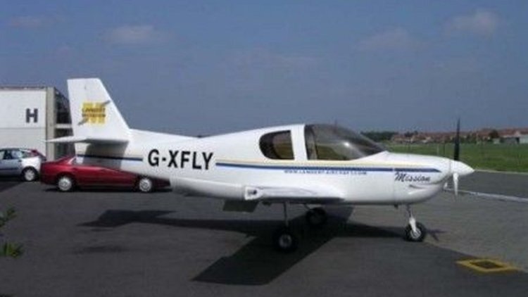
The Lambert Mission 212 is a conventionally laid out low-wing, fixed undercarriage, single-engine, four-seat kit built aircraft designed in the UK by a Belgian college student. Kits are manufactured in Belgium. The M212 has had an unusually long gestation time. It was designed in 1992 by Filip Lambert, then a student at the College of Aeronautics, Cranfield, and was selected as one of three winners of the Royal Aeronautical Society Light Aircraft Competition in 1995. Construction of the M212-100 prototype began in 1996. This aircraft was registered in the UK in 2000 and was displayed, complete apart from some engine and fuel supply systems, at the Popular Flying Association (PFA) Rally held at Cranfield in June 2002. The first flight, delayed by another two years, took place on 13 April 2004 at Cranfield with Roger Bailey as pilot. The M212 is an all-composite aircraft with 95% of its weight in pre-pregs. The wing has two main spars plus an auxiliary one, all formed from glass and carbon fibre in epoxy resin. In plan the wing is gently straight tapered, with most sweep on the trailing edge and with turned up wingtips. It has 5° of dihedral and 2° of washout. Electrically actuated single slot flaps are fitted. Fin and rudder are swept, with a small dorsal fin; the rudder is horn-balanced. The tailplane is rectangular and set a little above the fuselage, carrying inset elevators. The fuselage is a monocoque construction, tapering strongly to the rear. The cockpit seats four in two rows with dual controls in front, covered by a forward-hinged, single-piece canopy. There are two side windows for the rear seat passengers. The M212 has a fixed tricycle undercarriage, the mainwheels mounted on forward-leaning cantilever legs in narrow chord fairings, attached to the fuselage. The mainwheels have brakes and the nosewheel is steerable. Only 2 examples were built. More details here.

-
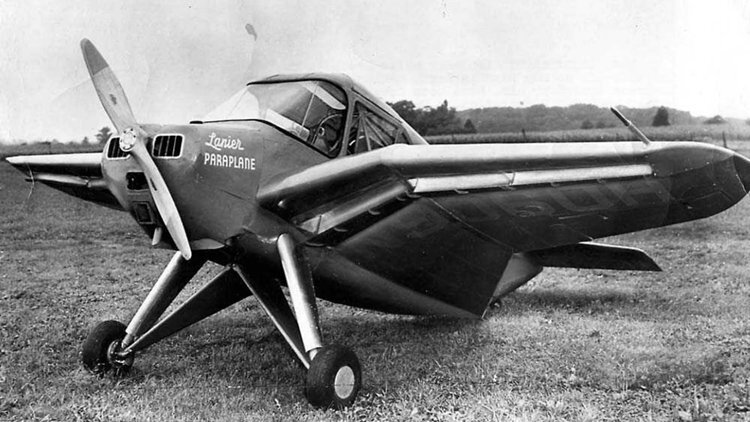
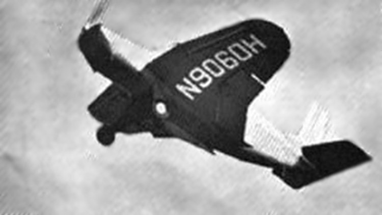
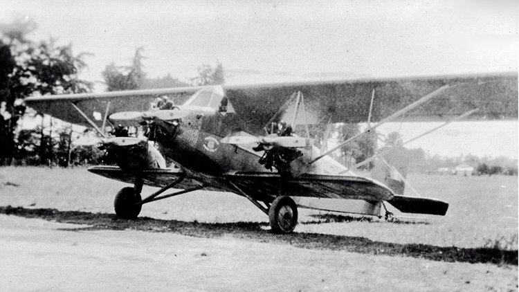
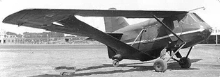
The 1958 Lanier Paraplane Commuter 110 or 110 Paraplane Commuter PL-8 was one of the last designs stemming from Edward H. Lanier's 1930s patents, and aircraft incorporating apertures in the upper surfaces, which claimed to give benefits in safety, lift and STOL ability. In the early 1930s Edward H. Lanier published six US patents concerned with increased aircraft lift and stability, minimising the stall, sideslip and spin. This was to be achieved through vacuum chamber ("Vacua-cells"), initially in the upper fuselage but later in the upper wing, where the reduced pressure established by airflow over a curved surface would act on the lower surface inside the cell, providing lift. The second patent suggests that the cell should contain angled spanwise slats to prevent air entering them at low speeds and that these should be adjustable so that the cells could be closed when required. The earlier patents stress stability improvements; claims of enhanced lift begin with the fourth patent. Five Lanier Vacuaplanes were built in the 1930s, followed by three Paraplanes from about 1948, before the Paraplane Commuter 110 which first flew in 1958. The Commuter 110 had a wing area of 111 sq ft (10.3 m²), large for its 20 ft 7 in (6.28 m) span, and controllable air entrance slots ("Vacua-Jets") under the lower surface near its leading edge, passing air to the upper surface for boundary layer control. Other details of the upper surface are scarce but photographs appear to show rear hinged, single-piece slats over Vacua-cells as well as narrow open channels next to the fuselage in the very long wing root fairings. Structurally, the cantilever mid wing had strongly cranked inner sections and was tapered in plan with elliptical wing tips. The outer panels carried control surfaces which operated differentially as ailerons and together as flaps. In addition there were split flaps under the trailing edges of the wing roots. More details here.
-
Two model aero clubs in Melbourne's east that I know of, Knox Model Aero Club on Stud Road, Knoxfield, with three control line circles, and Doncaster Aeromodellers Club on Bulleen Road, Bulleen, with one control line circle and a grass runway for RC models. Both can be searched on Google Maps.
-
The Johns Ra-Son Warrior or X-3 Warrior is a low wing bushplane with a large short coupled tail surface. The aircraft has a large tapered low wing, with a large horizontal tail surface mounted close to the trailing edge of the wing and conventional tailwheel landing gear. The fuselage has welded steel tube construction with fabric covering. The wings have fabric-covered wooden ribs and spars. A 1,000 lb (454 kg) payload can be lifted by the 185 hp (138 kW) engine. The five-seat cabin can be converted for cargo operations, and two oversized gullwing cabin doors allow loading. The prototype was built over a four-year period. The aircraft received the Experimental Aircraft Association award for achievement in 1963.
-
An Air India plane plunged 900ft during its flight just two days after the disaster crash that killed 241 people onboard and dozens more on the ground, the airline has revealed. The plane, flying from Indira Gandhi International (IGI) Airport for Vienna, dropped 900ft in midair during a flight on June 14. It landed safely in Vienna following a nine-hour flight, but both pilots onboard have since been grounded pending an investigation by India's air watchdog, the Directorate General of Civil Aviation (DGCA), into the incident, Air India said.
-
 https://www.msn.com/en-au/news/australia/the-long-awaited-new-qantas-plane-touches-down-in-soggy-sydney/ar-AA1HNrPH?ocid=winp2fptaskbarhover&cvid=fbc70d7c517d43c391a6324c08424e44&ei=28
-
- 1
-

-
https://www.msn.com/en-au/motoring/news/china-s-first-mass-produced-flying-car-debuts/vi-AA1HMzza?ocid=winp2fptaskbarhover&cvid=6039463e2fc74a20ba8b65e00c4c5219&ei=44
-
Typical press (or TV) ignorance. I saw a graphic on the TV about a Boeing Airbus.
-
Reports this morning that the Airbus was parked incorrectly.
-
https://x.com/FlightModeblog/status/1938862373424537667
-
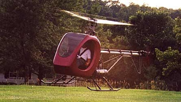
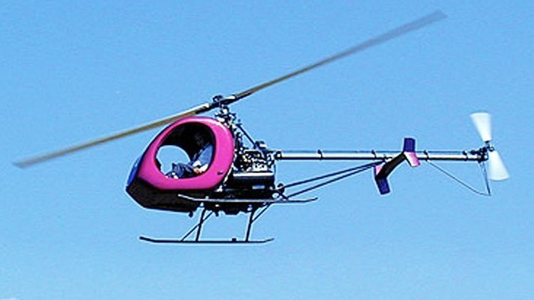
The Kinney HRH (Hot Rod Helicopter) is an American helicopter that was designed by Robert Kinney and produced by Vortech, Inc in the form of plans for amateur construction. The aircraft was first shown at Sun 'n Fun in 2002. The HRH was designed to comply with the US experimental – amateur-built rules. It features a single main rotor, a single-seat enclosed cockpit with a windshield, skid-type landing gear and a four-cylinder, air-cooled, four-stroke, 165 hp (123 kW) Subaru EJ25 automotive engine. It is the high power to weight ratio that gives the aircraft its name. The aircraft fuselage is made from a mix of welded 4130 steel tube and bolted-together aluminum tubing, with a composite cabin shell. Its 25 ft (7.6 m) diameter two-bladed Waitman composite rotor has a chord of 8 in (20 cm). The tail rotor has a 46 in (117 cm) diameter. The aircraft has an empty weight of 1,000 lb (454 kg) and a gross weight of 1,350 lb (612 kg), giving a useful load of 350 lb (159 kg). With full fuel of 18.5 U.S. gallons (70 L; 15.4 imp gal) the payload is 239 kg (527 lb). The HRH can hover in ground effect at 7,000 ft (2,134 m) and out of ground effect at 5,000 ft (1,524 m). By January 2013 there was one example, the 2001 prototype, registered in the United States with the Federal Aviation Administration.
-
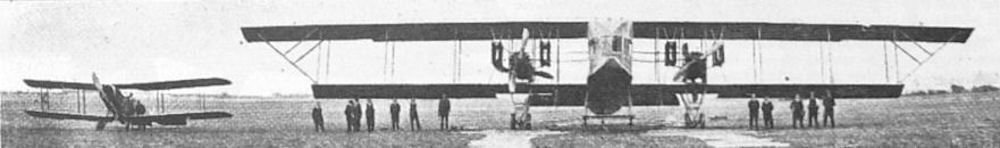
The Kennedy Giant was a British biplane heavy bomber designed by Kennedy Aeroplanes Ltd. during the First World War. The design was an imitation of works by Igor Sikorsky, with whom the owner of Kennedy Aeroplanes Ltd., C. J. H. Mackenzie-Kennedy, had ostensibly worked prior to setting up the company. The aeroplane was a notorious failure; its size meant that construction had to take place in an open field as none of the hangars near Hayes, Middlesex, where the prototype was assembled, were large enough to house it. For its weight, the aircraft's four engines were inadequate, and the resulting under-powered aircraft could only fly in a straight line once airborne. Following the unimpressive test flight, the design was cancelled and the prototype was left derelict at Northolt Aerodrome for a number of years.
-
-
 The Howland H-2 Honey Bee is an American homebuilt aircraft that was designed by Bert Howland and made available by Howland Aero Design in the form of plans for amateur construction, with kits provided by Aircraft Spruce & Specialty Co. The H-2 first flew in 1986. The H-2 is a single-seat, open cockpit biplane, with conventional landing gear and a single engine in tractor configuration. The aircraft is made from aluminium and covered in doped aircraft fabric covering. The fuselage is made from square aluminum tubing that is TIG welded and weighs 24 lb (11 kg) when completed. Its 19 ft (5.8 m) span wings are of a straight planform and both of equal span. The wings have seven foam wing ribs per wing panel and incorporate a D-cell front spar and a C-channel rear spar. The landing gear is conventional, with suspended main wheels and a steerable tailwheel. The H-2 has an open cockpit, with a small windshield. Controls are conventional three-axis, with ailerons, rudder and elevator. The standard design has two ailerons, with four optional. Since the death of the designer plans have been intermittently available and were last provided by Classic Aero Enterprises. Aircraft Spruce and Specialty continue to provide raw materials kits. The aircraft has an acceptable power range of 40 to 95 hp (30 to 71 kW) and the Hirth 2706 of 65 hp (48 kW) is the standard engine recommended. Installation of the 95 hp (71 kW) Hirth F30, or an equivalent engine, along with an inverted fuel system, allows intermediate level competition aerobatics. The plans consist of 40 engineering drawings and a booklet of construction notes. Estimated building time is 800 hours. Variants H-2 Base model with two ailerons and a 65 hp (48 kW) Hirth 2706 engine H-2A Aerobatic competition model with four ailerons, inverted fuel system and a 95 hp (71 kW) Hirth F30 engine
 -
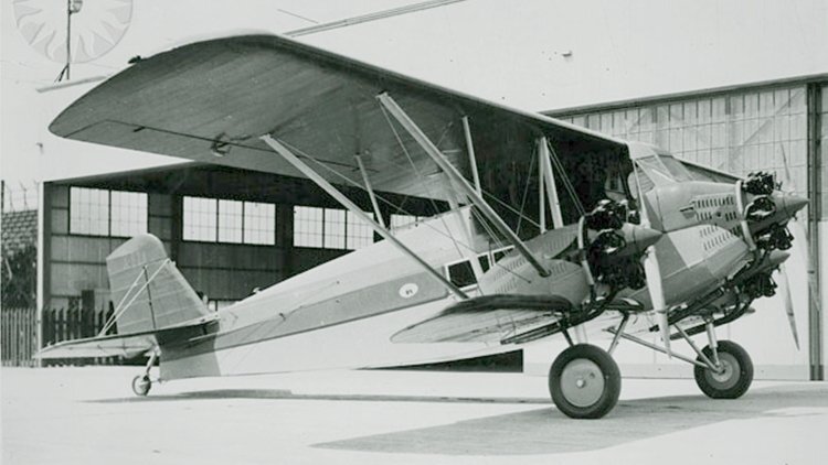
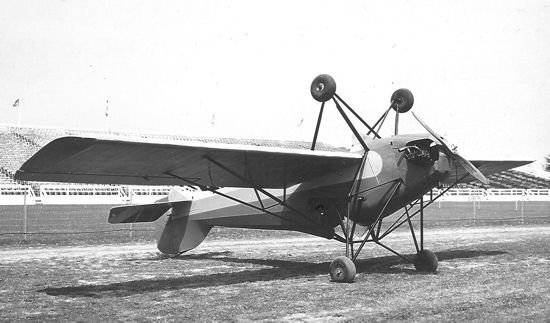
The Hodkinson HT-1 was a U.S., eight place, three-engined sesquiplane, first flown in 1929. Despite an order for five, only one had been completed before Hodkinson Aircraft went bankrupt near the start of the Great Depression. It operated in Guatemala for several years. Hodkinson Aircraft was founded in 1929 by William Wadsworth Hodkinson, one of the pioneers of the film industry who in 1916 had organized Paramount Pictures. He later went into film distribution, founding the W.W.Hodkinson Co. and then moved into the aviation business. The HT-1 was built by Valley Manufacturing Co. a division of Hodkinson Aircraft based in Glendale, California. Its designer, Don R. Berlin, later designed the Curtiss P-40. The wings of the HT-1 were both built around spruce spars and had rectangular plans out to rounded tips. The upper wing, with three-quarters of the total wing area, provided most of the lift and mounted narrow chord, Friese ailerons that reached from wingtips to above the outer engines. The short, lower wings were braced to the upper ones with parallel interplane struts between the wing spars. The HT-1 was powered by three 170 hp (130 kW) Curtiss Challenger radial engines, one in the nose and the others on top of the lower wing, braced by vertical struts to the upper spars. Behind the central engine the fuselage was flat sided, with the wing centre-section fixed to it by inverted V cabane struts faired into the fuselage's chrome-molybdenum tube structure. These provided a clear rear view from the pilots' cabin under the leading edge of the wing. Pilot and co-pilot sat side-by-side with dual controls, though the co-pilot's controls could be removed to allow an extra passenger to be carried. Their cabin was normally accessed through doors on either side but there was also a door in the rear which led down to the passengers' windowed, six seat cabin. There was a toilet at the back and also a baggage compartment, though this was only accessible from outside. Cabin access was via doors on either side, opening just ahead of the rear seats. Its tail was conventional, The fixed surfaces, like the fuselage, had chrome-molybdenum tube structures and the tailplane was mounted on top of the fuselage. The fin was braced to the tailplane and had a cropped, roughly triangular profile. The balanced rudder had a blunted rectangular profile.
-
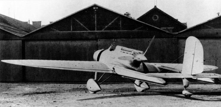
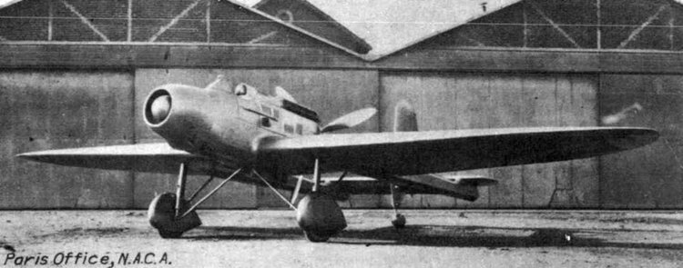
The Hanriot H.110 was an unusual pusher configuration, twin boom, single seat fighter aircraft built in France in the early 1930s. It proved to be slower and less manoeuvrable than its contemporaries and failed to reach production, even as the Hanriot H.115 after receiving a more powerful engine and cannon armament. From 1916 until 1933, the only Hanriot fighter aircraft had been tractor biplanes. The Hanriot H.110, a twin boom pusher cantilever monoplane was therefore a considerable departure from the past. It was designed to compete in the STAé (Service Technique de l'Aéronautique or Technical Section of Aeronautics) 1930/31 C1 (single seat Chasseur of fighter) programme. The all-metal H.110 had an open cockpit and engine in a short central nacelle. It was powered by a 485 kW (650 hp) Hispano-Suiza 12Xbrs supercharged upright water-cooled V-12 engine behind the pilot, driving a three-blade pusher propeller. The pilot's headrest was smoothly faired into the engine cowling. There was a circular Chausson radiator in the short nose ahead of the open cockpit, with a variable position central cone to control the airflow. The wings were built around two spars. The central 25% of their span, between the booms, had constant chord. Immediately outboard they had a wider chord and beyond were double straight tapered to rounded tips. They carried almost full-span, narrow-chord Frise ailerons. Forward, the slim, square section and untapered tail booms blended into the wings at about mid-chord, the aft ends carrying a constant-chord tailplane slightly above them. This had rounded tips and a central elevator with a trim tab. A central, single, tall, round-tipped, wire-braced vertical tail was mounted on in it. The H.110 had a fixed, split, conventional undercarriage with each spatted mainwheel on a faired, near vertical shock absorber and a rearward leaning strut together forming a V, laterally braced with an inverted V-strut attached near the under-fuselage centre line. There was a central tailwheel on a long leg under the fin. The H.110 began flight testing in April 1933. Tested against its smaller and lighter competitors, it proved slower and less manoeuvrable and was returned to Hanriot for modification. It flew in April 1934 as the H.115, with its HS 12Xbrs engine uprated to 515 kW (691 hp), a new four-blade propeller with variable-pitch and a revised nacelle, shortened forward of the cockpit by 360 mm (14.2 in). A 33 mm (1.30 in) APX cannon was now housed in a fairing below the nacelle as an alternative to the earlier pair of Chatellerault 7.5 mm (0.295 in) machine guns. With its new engine and propeller the H.115 was quicker than the earlier version, with a top speed of 390 km/h (242 mph). After more modifications over the winter of 1934-5 it returned to Villacoublay in June 1935 and was officially flight tested until mid August, but failed to attract a contract.
-
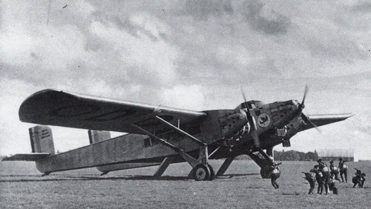
The Dyle et Bacalan DB-70 was a large three engine French airliner with a thick airfoil centre section which accommodated the passengers. Two fuselages, part of the centre section at the front but distinct further aft, carried the empennage. First flown in 1929, only one was built. In 1925 the large naval ship builders Société Anonyme de Travaux Dyle et Bacalan, established in 1879 and based in Bordeaux, developed an aircraft manufacturing interest. They built several all-metal prototypes incorporating very thick wings. The DB-70 was the largest of these and the last to carry the company name: Dyle et Bacalan ceased trading in July 1929, before the DB-70 had flown, though the company reformed as Société Aérienne Bordelaise (SAB) that same month. As a result, the aircraft is sometimes referred to as the SAB DB-70; the letter prefix DB was retained, though aircraft designed later by SAB used the AB- form . The DB-70 was a very large, all metal aircraft built, like all Dyle et Bacalan aircraft, largely of duralumin. As on the 1926 DB-10, the centre section of the wing of the DB-70 was extremely thick and twice the chord of the outer wings, with a chord/thickness ratio of about 25%. The layout of the two designs was different, though; the otherwise conventionally laid-out DB-10 had thick wings inboard of its two engines, whereas the DB-70 was built around its thick centre section with twin fuselages, developed from it rearwards, carrying the empennage. The centre section also mounted the three 450 kW (600 hp) Hispano-Suiza water-cooled inline engines and the pilots' cockpit and enclosed the passenger accommodation. More details here.
-
Like their train passenger loads.
-
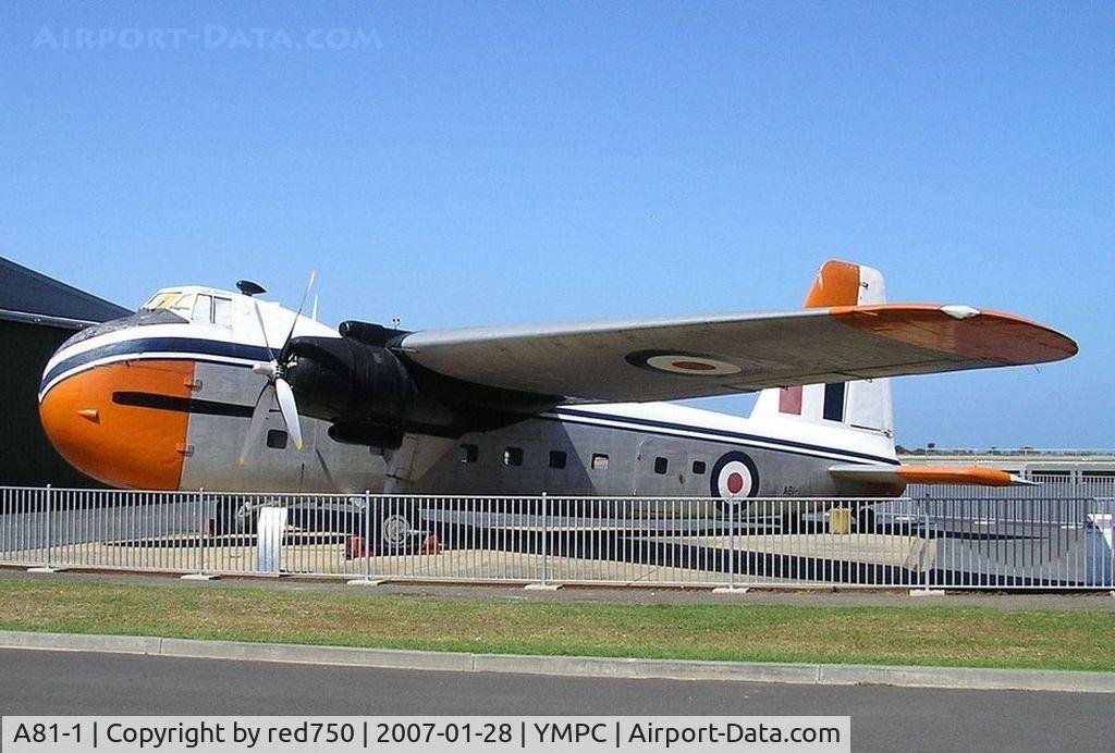
There is, or was, a Mk 21 Bristol Freighter, A81-1, at RAAF Museum, Point Cook, when I took this photograph on 28 Jan, 2007.
-
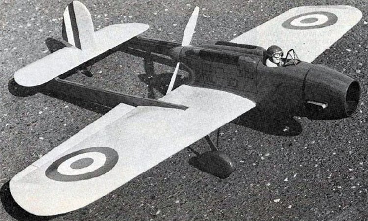
Also known as the Brown Potato Bug. The wing support (middle) was also a wing, so it was a triplane.
-
-
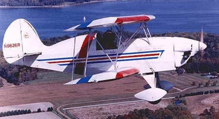
It's a Murphy Over and under, built by exhibition pilot Mike Murphy.
-
Report on TV today that one engine was brand new and the other not due for service till December.
-
Resurecting this old thread - there are a number similar. I came across this image, and know what it is, but thought I'd see who else knew.
-
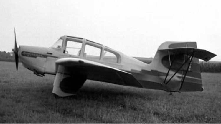
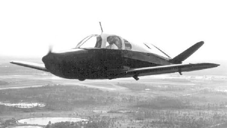
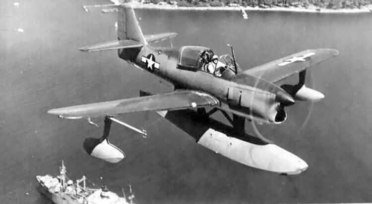 The Edo OSE was a 1940s American single-seat multi-role floatplane designed and manufactured by the Edo Aircraft Corporation. The Edo Aircraft Corporation was an established company that produced seaplane floats. In 1946, Edo designed its first aircraft, the Edo OSE. Two prototype aircraft (designated XOSE-1) were built and flown in 1946. The XOSE-1 was a single-seat low-wing cantilever monoplane with a single float and fixed wingtip stabilizing floats. The wings could be folded for shipboard storage. The aircraft was designed for a variety of roles including observation and anti-submarine patrols. Unusually, it was designed to carry a rescue cell on the underwing hardpoints, which would be capable of carrying a single person when used for air-sea rescue. Eight production aircraft (designated XOSE-1) were built to a United States Navy order but none were accepted into service. A two-seat training conversion was carried out as the XTE-1, but production TE-2 aircraft were cancelled. Variants XS2E-1 Original designation for OSE and TE single seat floatplane scouts. XOSE-1 Prototypes and production single-seat aircraft redesignated from XS2E-1; eight built. XOSE-2 Prototype two-seat floatplane scout aircraft, two converted from XOSE-1. OSE-2 Production two-seat floatplane scout aircraft, four aircraft were assigned Bureau of Aeronautics numbers (BuNos.), but production was cancelled. XSO2E-1 Original designation for XTE-1 conversions. XTE-1 Two-seat floatplane trainer conversions, two aircraft converted from the XOSE-1 prototypes. TE-2 Developed from the TE-1, four aircraft were assigned BuNos., but production was cancelled.