red750
-
Posts
7,796 -
Joined
-
Last visited
-
Days Won
68
Content Type
Profiles
Forums
Gallery
Downloads
Blogs
Events
Store
Aircraft
Resources
Tutorials
Articles
Classifieds
Movies
Books
Community Map
Quizzes
Videos Directory
Everything posted by red750
-
 Klemm L 25, later Klemm Kl 25 is a successful German light leisure, sports and training monoplane aircraft, developed in 1928. More than 600 aircraft were built, and manufacturing licenses were sold to the United Kingdom and the United States. With a low cantilever wing, fixed landing gear, and two open cockpits, the aircraft was developed by Hanns Klemm, who used his previous design, the Daimler L20, as a starting point. It first flew on a 20 hp (15 kW) Daimler F7502 engine. About 30 different versions of the Kl 25 were made, and these were equipped with engines ranging from 32 to 70 kW (43 to 94 hp). The fuselage was covered with plywood. Depending on the model, the aircraft's weight was 620 to 720 kg (1,367 to 1,587 lb), and it had a 10.5 to 13 m (34 to 43 ft) wingspan. Takeoff was achieved at only 50 km/h (31 mph) and the maximum speed was between 150 and 160 km/h (93 and 99 mph). In relation to similar aircraft of the time, assembly was very easy, and this made it a very popular aircraft. According to the sales brochures, only 25% of the engine's power was needed to keep the aircraft flying, compared to biplanes of the period, which required 50% engine power. About 600 were built in Germany between 1929 and 1936, serving with various flight training organizations, with either wheels, skis, or floats. 15 were sold to Britain before the Second World War, being fitted with a variety of domestic engines, while 28 more were built by British Klemm Aeroplane Company as the B.A. Swallow. Production in the United States was carried out by the Aeromarine-Klemm Company which enjoyed moderate success, as well as developing models for the American market, in isolation from the parent company, with about 120 built of all models. Klemm L 25s took part in many competitions, among others in International Touring Aircraft Competitions (Europa Rundflug) in 1929 (best 4th place) and in 1930 (best 2nd and 3rd places, L 25E variant). A total of about 720 units were buillt. Variants Germany L 25 a Built between 1927 and 1929, equipped with a 22 PS (21.7 hp; 16.2 kW) Daimler F 7502 engine L 25 I Built between 1928 and 1929, equipped with a 45 PS (44.4 hp; 33.1 kW) Salmson AD.9 engine L 25 Ia (Specifications below) L 25 IW Floatplane version of the Ia, with two wooden floats supported by steel-tube struts in inverted 'W' configuration L 25 b Built in 1931, equipped with a 22 PS (21.7 hp; 16.2 kW) Daimler F 7502 engine L 25 b VII Built in 1931, equipped with a 60 PS (59.2 hp; 44.1 kW) Hirth HM 60 engine L 25 d II Built in 1933, equipped with an 88 PS (86.8 hp; 64.7 kW) Siemens-Halske Sh 13a engine Klemm L.25 d VII R built in 1934 L 25 d VII Equipped with an 80 PS (78.9 hp; 58.8 kW) Hirth HM 60R engine L 25 IVa Equipped with Armstrong Siddeley Genet engine VL 25 Va Three-seater variant, with a closed canopy, equipped with 103 PS (101.6 hp; 75.8 kW) Argus As 8 straight engine[2] L 25 Ve (see L 25E) For Europa Rundflug 1930 L 25E (L 25 Ve) Special competition variant (E for Europa Rundflug 1930), with a closed canopy, smaller span, equipped with a 103 PS (101.6 hp; 75.8 kW) Argus As 8 United Kingdom British Klemm Aeroplane Company B.K. Swallow British Aircraft Manufacturing Co. B.A. Swallow II United States Aeromarine-Klemm AKL-25 Aeromarine-Klemm AKL-70 Aeromarine-Klemm Model 70 Trainer
 -
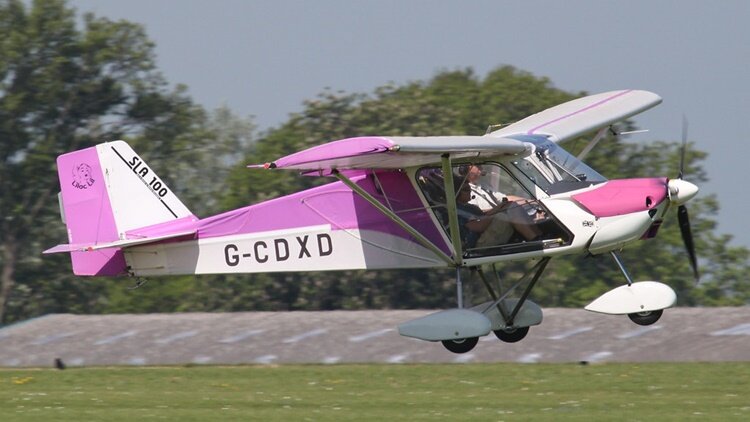 The Medway SLA100 Executive, also called the Medway SLA 100 Executive, is a British ultralight aircraft designed and produced by Medway Microlights, of Rochester, Kent. The aircraft is supplied as a kit for amateur construction or as a complete ready-to-fly-aircraft. The aircraft was designed to comply with the British BCAR Section "S" and the Fédération Aéronautique Internationale microlight rules. It features a strut-braced high-wing, a two-seats-in-side-by-side configuration enclosed cockpit, fixed tricycle landing gear and a single engine in tractor configuration. The SLA100 is made from bolted-together aluminium tubing, with its flying surfaces covered in Dacron sailcloth. Its 9.7 m (31.8 ft) span wing has an area of 13.8 m2 (149 sq ft) and is supported by V-struts with jury struts. Standard engines available are the 80 hp (60 kW) Rotax 912UL and the 100 hp (75 kW) Rotax 912ULS four-stroke powerplants. The SA100 has been certified to the UK BCAR Section "S" standard. Variants SLA100 Executive Standard model with a 9.7 m (31.8 ft) wing span SLA100 Clipper Clipped wing model, introduced in 2010 and still under development in 2015.
 -
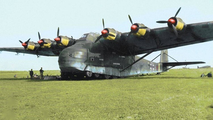 The Messerschmitt Me 323 Gigant ("Giant") was a German military transport aircraft of World War II. It was a powered variant of the Me 321 military glider and was the largest land-based transport aircraft to fly during the war. In total, 213 were made, with 15 being converted from the Me 321. The Me 323 was the result of a 1940 German requirement for a large assault glider in preparation for Operation Sea Lion, the projected invasion of Great Britain. The DFS 230 light glider had already proven its worth in the Battle of Fort Eben-Emael in Belgium (the first ever assault by gliderborne troops), and would later be used in the invasion of Crete in 1941. However, in order to mount an invasion across the English Channel, the Germans would need to be able to airlift vehicles and other heavy equipment as part of an initial assault wave. Although Operation Sea Lion was cancelled, the requirement for a heavy air transport capability remained, with the focus shifting to the forthcoming Operation Barbarossa, the invasion of the Soviet Union. Early in 1941, as a result of feedback from Transport Command pilots in Russia, the decision was taken to produce a motorized variant of the Me 321, to be designated Me 323. French Gnome et Rhône GR14N radial engines, rated at 1,180 PS (1,164 hp, 868 kW) for take-off as used in the Bloch MB.175 aircraft were chosen for use. This would reduce the burden on Germany's strained industry. Like the Me 321, the Me 323 had massive, semicantilever, high-mounted wings, which were braced from the fuselage out to the middle of the wing. To reduce weight and save aluminium, much of the wing was made of plywood and fabric, while the fuselage was of metal-tube construction with wooden spars and covered with doped fabric, with heavy bracing in the floor to support the payload. The "D" series had a crew of five - two pilots, two flight engineers, and a radio operator. Two gunners could also be carried. The flight engineers occupied two small cabins, one in each wing between the inboard and centre engines. The engineers were intended to monitor engine synchronisation and allow the pilot to fly without worrying about engine status, although the pilot could override the engineers' decisions on engine and propeller control. For more details of development, design, operational history and 18 variants, click here.
 -
 The North American FJ-4 Fury is a swept-wing carrier-capable fighter-bomber for the United States Navy and Marine Corps. The final development in a lineage that included the Air Force's F-86 Sabre, the FJ-4 shared its general layout and engine with the earlier FJ-3, but featured an entirely new wing design and was a vastly different design in its final embodiment. Compared to that of the FJ-3, the FJ-4's new wing was much thinner, with a six percent thickness-to-chord ratio, and featured skin panels milled from solid alloy plates. It also had an increased area, and tapered more sharply towards the tips. Slight camber behind the leading edge improved low speed characteristics. The main landing gear design had to be considerably modified to fold wheel and strut within the contours of the new wing. The track of the main wheels was increased and because they were closer to the center of gravity, there was less weight on the nosewheel. Wing folding was limited to the outer wing panels. The FJ-4 was intended as an all-weather interceptor, a role that required considerable range on internal fuel. The FJ-4 had 50% more fuel capacity than the FJ-3 and was lightened by omitting armor and reducing ammunition capacity. The new wing was "wet"; that is, it provided for integral fuel tankage. The fuselage was deepened to add more fuel, and had a distinctive "razorback" rear deck. A modified cockpit made the pilot more comfortable during the longer missions. The tail surfaces were also extensively modified and had a thinner profile. The overall changes resulted in an aircraft that had little in common with the earlier models, although a family resemblance was still present. The two prototypes had the same Wright J65-W-4 engine as the FJ-3, but production aircraft had the J65-W-16A of 7,700 lbf (34 kN) thrust. The first FJ-4 flew on 28 October 1954 and delivery began in February 1955. Of the original order for 221, the last 71 were modified in the FJ-4B fighter-bomber version. This had a stronger wing with six instead of four underwing stations and stronger landing gear. Additional aerodynamic brakes under the aft fuselage made landing safer by allowing pilots to use higher thrust settings, and were also useful for dive attacks. External load was doubled. The most important characteristic of the FJ-4B, however, was that it was capable of carrying a nuclear weapon on the inboard port station. It was equipped with the LABS or Low-Altitude Bombing System for the delivery of nuclear weapons. The Navy was eager to maintain a nuclear role in its rivalry with the Air Force, and it equipped 10 squadrons with the FJ-4B. It was also flown by three Marine squadrons. In April 1956 the Navy ordered 151 more FJ-4Bs, for a total of 152 FJ-4s and 222 FJ-4Bs produced, and 1,115 FJ aircraft of all variants delivered to the Navy and Marine Corps. The Navy ordered six FJ-4s to be converted to FJ-4F to test rocket engines, but only two were completed. These featured the North American Rocketdyne AR-1 engine, installed in a fairing above the tail pipe of the jet engine. It ran on hydrogen peroxide and JP-4 jet fuel, and provided an additional 5,000 lbf (22 kN) of thrust for short periods. The FJ-4F reached speeds of Mach 1.41 and altitude of 71,000 ft (21,600 m). With the 1962 adoption of the Tri-Service aircraft designation system, the FJ-4 became the F-1E and the FJ-4B the AF-1E. AF-1Es served with United States Naval Reserve units until the late 1960s. Number built 374 Variants XFJ-4 Two prototypes with a J65-W-4 engine and re-designed fuselage. YFJ-4 One FJ-4 used for development testing. FJ-4 Fury Single-seat fighter-bomber version, powered by a 7,700 lbf (34 kN) Wright J65-W-16A turbojet engine, 150 built. FJ-4B Fury Single-seat ground-attack close support version with six underwing pylons, 222 built. FJ-4F Fury Test and evaluation aircraft, fitted with an auxiliary rocket motor and supplementary fuel tank, two conversions from FJ-4. F-1E Fury Redesignation of the FJ-4. AF-1E Fury Redesignation of the FJ-4B. AF-1F (NA-295) Proposed light-attack version with TF30 engine, competitor to the A-7; not built.
 -
 The Jeffair Barracuda is a high-performance sporting monoplane that was developed in the United States in the 1970s and is marketed for homebuilding. Designed and built by Geoffrey Siers, the prototype won the prize for "Most Outstanding New Design" at the EAA Fly-in in 1976. It was a low-wing cantilever monoplane of wooden construction with retractable tricycle undercarriage and side-by-side seating for two. Around 150 sets of plans had sold by 1977. Geoffrey Siers was a former RAF pilot and engineer for Boeing in 1967. He set out to design an aircraft that was fast, aerobatic, two place, and had range to fly long cross-country flights. The aircraft was refined after a full size cockpit mockup was made. The lightweight construction of the plywood-covered wooden de Havilland Mosquito was the inspiration for the materials choice. The retractable landing gear came from a Piper PA-24 Comanche. The wings were a three-piece design. Test flights were performed in 1975. The aircraft takes off at 70 mph (113 km/h) and climbs at 2000 feet per minute (10.2 m/s). Full flap stalls were recorded as low as 54 mph (87 km/h).
 -
https://www.msn.com/en-au/news/world/air-india-crash-probe-focuses-on-engine-fuel-control-switches-the-air-current-reports/ar-AA1IdVPY?ocid=winp2fptaskbarhover&cvid=3eb0f1b15e064ce19a15c4cd4535a20a&ei=36
-
 The Metal Aircraft Flamingo was a monoplane produced in Cincinnati, Ohio by the Metal Aircraft Corporation in the 1930s. The Metal Aircraft Corporation purchased the design from the Halpin Development Co. and unveiled it at the 1929 National Air Races with Elinor Smith. Following an accident at Bowman Field in May 1928, the prototype Flamingo was redesigned with a different nose, windscreen, and tail. The interior was insulated with Balsam-Wool Blanket. The Flamingo was first flown from Lunken Airport on 8 April 1928 by Thomas E. Halpin. At one point, the aircraft carried an African-American porter in a red suit named Benny Smith. Following a teaser, marketing for the new airplane began in March 1929 and dealers were being solicited by the following month. One G-2-W, named El Rio Caroní, is best remembered for its role in the discovery of Angel Falls by Jimmy Angel in 1935. Although well known to the local indigenous population, the falls had been glimpsed only by European explorers until Jimmy Angel crash-landed while attempting to land above the falls on Auyán-tepui during gold exploration. The Metal Aircraft Corporation Flamingo that crashed above the falls was recovered by helicopter in the 1960s by the Venezuelan government and is on display at the entrance of the Ciudad Bolívar airport, in Venezuela. A replica was put in its place for visitors of the crash site. Other operators included the Mason & Dixon airline. Another operator of the aircraft was United States Airways which flew a route from Denver to Kansas City in the early 1930s. Stops were made Goodland, Salina, and Topeka, Kansas. Number built 21 Variants Halpin Flamingo six-passenger 410hp P&W G-1 five-passenger 450hp P&W G-2 six-passenger G-2-H six-passenger 525hp P&W G-2-W (Specifications below) eight-passenger 410hp P&W G-MT-6 five-passenger 410 or 525 P&W
 -
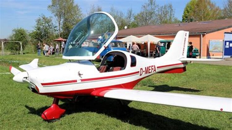
 The Jurca MJ-2 Tempete (French: "Tempest") is a single-seat sport aircraft designed in France in the mid 1950s and marketed for homebuilding. The Tempete is a low-wing cantilever monoplane of conventional configuration and utilising wooden construction throughout apart from the fabric covering of the flying surfaces. The undercarriage is of the fixed, tailwheel or tailskid type. The pilot's seat is enclosed by a bubble canopy; some aircraft have a second seat to carry a passenger of less than 55 kg (121 lb). The Tempête may be powered by a wide range of engines. At least 13 possibilities have been listed, each with its own suffix letter. These engines are all either Continental or Lycoming horizontally opposed types in the power range 48.5 - 134 kW (60-180 hp). The French and UK civil registers contain examples with seven different engines, the most popular choice being the 67 kW (90 hp) Continental C90 fitted to the Tempête MJ-2D model. The Jurca MJ-3 Dart was a one-off sport aircraft which was constructed in the United States in 1977. It was built by Denis Jacobs of Dayton, Ohio, marrying the fuselage of the single-seat Jurca Tempête with the wings of the two seat Jurca Sirocco. The Jurca Shadow was a variant with larger, swept back tail surfaces. The Tempête has been flown since 1957 by private owner and sporting pilots. There have been 37 on the French register, though 4 of these have been withdrawn as of September 2010. Two Tempêtes have UK Permits to Fly in 2010. In 2000 there were several flying in the USA. . Marcel Jurca died 19 October 2001 but plans are still available in 2009 from the designer's web site. Variants MJ-2 MJ-20 (never built) MJ-22 - Strengthened version with a 112 kW (150 hp) engine MJ-23 Orage ("Thunderstorm") - high-performance version with trapezoidal wings and intended for a 300-hp engine (never built) MJ-3 Dart - MJ-2 modified (1 built) MJ-4 Shadow - Version with enlarged, swept empennage (2 built)
 -
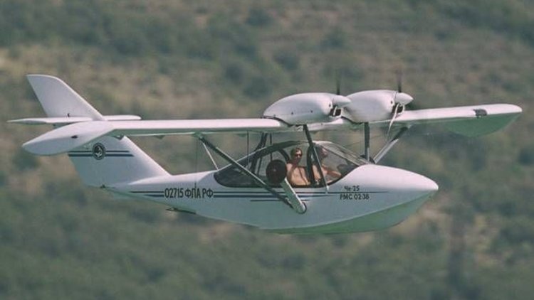
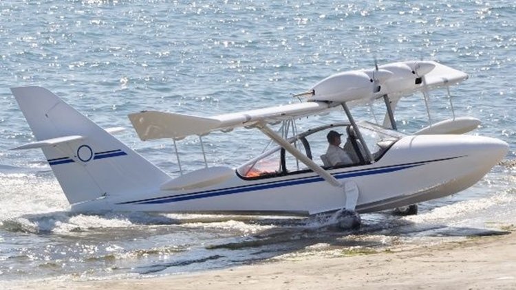
There is a very similar amphibious version called the Gidroplan Che-22 Korvat, (Corvette), for which there is currently no Wikipedia page.

-
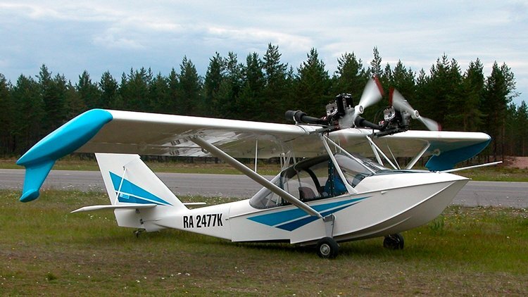
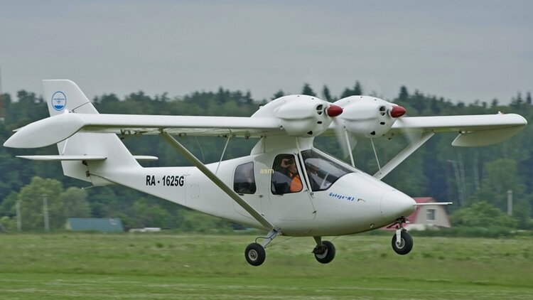 The Gidroplan Tsikada (Гидроплан Цикада or Hydroplane Cicada) is a light, twin engined utility aircraft, seating two or four in different variants, developed in Russia since about 2000. At different times and in different places the Tsikada or Sky Wind series has been marketed either under the company name, Gidroplan, or under its English translation, Hydroplane. The earliest Tsikada was shown in 2000 and was a high-wing monoplane, with twin engines mounted above and forward of the wing leading edge. This arrangement has been maintained through later versions. The original aircraft was a two seater with two doors, powered by 48 kW (64 hp) Rotax 582 engines. It was followed in 2007 by the Tsikada-M or Sky Wind 1, which had more powerful Jabiru engines and modifications to the fuselage and cabin, the undercarriage and the control systems. A four-seat prototype, the Tsikada-3M, preceded a four-seat, four-door, four-window production version known as the Tskiada-4 or Sky Wind-AT, which is 400 mm (15.7 in) longer than before. The earlier flaperons were replaced with separate flaps and ailerons. The prototype finished flight trials in July 2009 and the Tsikada-4 was first flown in August, followed by production the following year. The Tsikada has a metal wing, rectangular in plan and with small downturned tips. The engines are mounted over the wing as close together as the propeller discs allow. They, and the wing centre section are supported over the fuselage by a short cabane; a single faired strut on each side braces the wing to the lower fuselage, assisted by a jury strut. The composite skinned fuselage has one or two rows of side by side seats, each with a pair of side windows in the doors, behind a single piece windscreen. There is a baggage compartment with a maximum load of 40 kg (88 lb). Aft of the cabin the fuselage tapers, with an upswept underside, to a tall swept fin and balanced rudder. The rectangular tailplane, externally braced from above and carrying separate, unbalanced elevators with a cut-out for rudder movement, is mounted on the fin a little above the fuselage. The tricycle undercarriage has mainwheels on sprung cantilever legs and a steerable oleo sprung nose wheel. A chemical hopper with underwing spray bar and discharge chute from the central fuselage underside is an option. Three Tsikada-Ms were supplied to Cuba, the first for anti-mosquito spraying, between 2008 and 2010. In all, six two-seat Tsikadas were built. Variants Tsikada Original Rotax powered two-seater Tsikada-M (Sky Wind-1) Jabiru powered two-seater Tsikada-M3 Four seat Tsikada-4 development aircraft Tsikada-4 (Sky Wind-AT) (Specifications below) Four seat, Jabiru powered The photo below (and above) is the only one found, even searching a Russian aircraft photo website. The Wikipedia page says at least 6 units have been completed.
 -
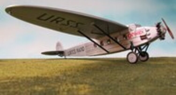 The Kalinin K-5 was an airliner produced in the Soviet Union in the 1930s, built in larger quantities than any other Soviet airliner of its time, with some 260 aircraft constructed. It was a conventional, high-wing, strut-braced monoplane with a fully enclosed cabin and cockpit, and followed the general pattern developed by Kalinin in his earlier designs, though on a larger scale. Kalinin had first considered an airliner for 10-12 passengers as early as 1926, but it was not until Ukrvozdukhput expressed interest in such a machine late the following year that work on the design began in earnest. The prototype was ready by mid-autumn 1929, and first flew on October 18 with Mikhail Artemevich Snegirev at the controls. Safety trials for the State Commission commenced on 30 May 1930, and were passed successfully. Ongoing problems with the aircraft's Gnome et Rhône-built Bristol Jupiter engine resulted in the second prototype being powered by a Pratt & Whitney Hornet instead. This machine undertook further testing and a number of promotional flights before series production of the K-5 commenced. Early production examples were used on trial services between Kharkiv and Moscow, Mineralnye Vody, and Baku. Problems with the Bessonov M-15 engines became quickly apparent, with frequent failures and operational lifespans measured in only dozens of hours. K-5 operations were suspended by the Inspectorate of Civil Aviation until the issues were resolved. Kalinin turned to the Shvetsov M-22 as an alternative powerplant. While reliability increased, this engine installation also created more drag than the M-15 had, and performance decreased accordingly. State Acceptance trials carried out in May–June 1932 confirmed the reliability of the engine with 550 takeoffs and landings and 2,000 steep turns, but found that the payload capacity was now unacceptably low. By this time, however, the M-15 had become reliable enough for restrictions to be lifted and K-5 production resumed, and eventually about 100 K-5s were fitted with this engine. The reliability of the revised M-15 design was vindicated by a gruelling flight through the Caucasus on 25 June 1933. Eventually, the Mikulin M-17F provided the definitive powerplant for the K-5, offering an increase in power and performance over the M-15, but decreasing the aircraft's payload and range due to its greater weight. The new engine also required strengthening of the wing design; the first K-5 fitted with this engine suffered structural damage during flight tests due to the increase in engine power. The K-5 was widely used by Aeroflot, displacing German-built Junkers F 13s and Dornier Komets in regular service. The first scheduled route flown by K-5s was Moscow-Kharkov, followed by services between Moscow and Sverdlovsk, Tashkent, and Arkhangelsk. They remained in service until 1940, becoming the backbone of Aeroflot's domestic operations. The K-5 was also used by the Soviet Air Force as a transport aircraft, operating in this capacity until 1943.
 -
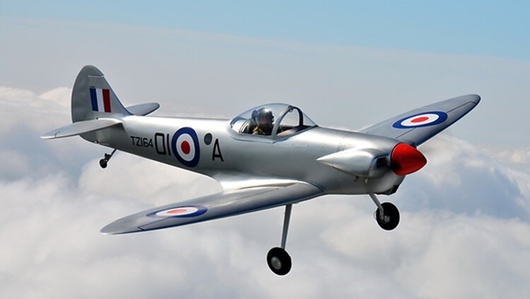 The Isaacs Spitfire is a single seat homebuilt sporting aircraft design created by John O. Isaacs, a former Supermarine employee and retired schoolmaster and designer of the Isaacs Fury, as a 6/10th scale replica of a Supermarine Spitfire. Its first flight was on 5 May 1975. As per the original Spitfire, the Isaacs Spitfire was a cantilever low-wing monoplane of semi-elliptical planform. The twin spar wing was built in one piece, mainly of spruce with birch plywood skin. The fuselage was of identical construction. The landing gear is fixed and included a tailwheel. Plans are available for sale to home constructors.
 -
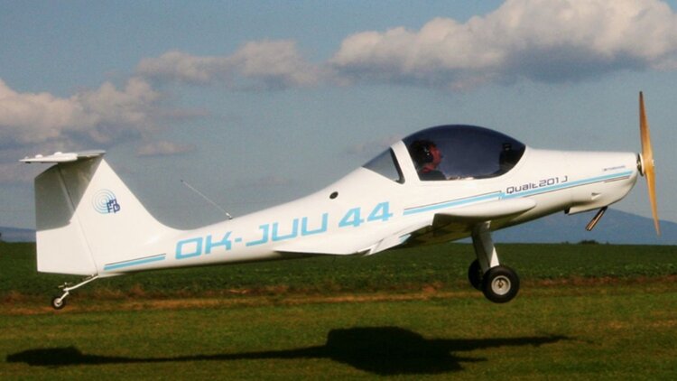 The FMP Qualt 201 is a Czech ultralight and light-sport aircraft, designed and produced by FMP s.r.o. of Prague. The aircraft is supplied as a complete ready-to-fly-aircraft. The Qualt 201 was derived from the earlier FMP Qualt 200, which it replaced in production. The 201 was designed to comply with the Fédération Aéronautique Internationale microlight rules and US light-sport aircraft rules. It features a cantilever low-wing, a two-seats-in-side-by-side configuration enclosed open cockpit under a bubble canopy, fixed conventional landing gear, a T-tail and a single engine in tractor configuration. The aircraft is made from composites. Its 9.2 m (30.2 ft) span wing has an area of 10.5 sq m (113 sq ft) and mounts split-style flaps. Standard engines available are the 64 hp (48 kW) Rotax 582 two-stroke, the 80 hp (60 kW) Rotax 912UL, the 100 hp (75 kW) Rotax 912ULS and the 85 hp (63 kW) Jabiru 2200 four-stroke powerplants.
 -
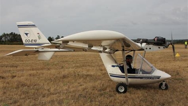 The Fly Synthesis Wallaby is an Italian two-seat, microlight monoplane manufactured by Fly Synthesis. The Wallaby is a high-wing monoplane with a high tail boom and with a 37 kW (50 hp) Rotax 503 piston engine fitted in front of the wing. Below the wing is an enclosed cabin with two seats and a fixed tricycle landing gear. The aircraft is available built or as a kit.[1] A Rotax 582 powered variant, the Wallaby R582 is also available. The design uses the wing from the Storch CL mated to a new high tailboom fuselage design, with the design goal of producing an economical aircraft.[3] The aircraft is sold as the Lafayette Wallaby in the United States. Reviewer Marino Boric described the design in a 2015 review as "very pleasant to fly". Variants Wallaby R503 Rotax 503 powered Wallaby R582 Rotax 582 powered
 -
 The Flaeming Air FA 04 Peregrine is a German ultralight and light-sport aircraft, designed and produced by Flaeming Air of Zellendorf, Brandenburg. The aircraft is supplied as a complete ready-to-fly-aircraft. The aircraft was designed to comply with the Fédération Aéronautique Internationale microlight rules and US light-sport aircraft rules, with different models for each category. It features a cantilever low-wing, a two-seats-in-side-by-side configuration enclosed cockpit under a bubble canopy, fixed tricycle landing gear, or optionally conventional landing gear and a single engine in tractor configuration. The aircraft is made from composites, with its fuselage, wing spars, flaps and rudder made from carbon fibre. Its 10.05 m (33.0 ft) span wing has an area of 9.27 sq m (99.8 sq ft). The standard engines available are the 100 hp (75 kW) Rotax 912ULS, 120 hp (89 kW) Jabiru 3300 and the 100 hp (75 kW) Continental O-200 four-stroke powerplants. The FA 04 can be used for aero-towing gliders up to 750 kg (1,653 lb) gross weight. Variants FA 01 Smaragd (Emerald) Initial model for the European FAI microlight class, with a gross weight of 472.5 kg (1,042 lb). FA 02 Kit aircraft with a gross weight of 650 kg (1,433 lb). FA 04 Peregrine Light-sport model for the US market, with a gross weight of 600 kg (1,323 lb). FA 04 SL Super-light model with an empty weight of 270 kg (595 lb), including a ballistic parachute.
 -
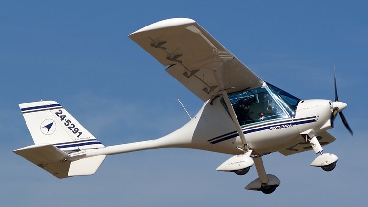 The Fly Synthesis Storch (English: Stork) is an Italian ultralight aircraft, designed and today produced by Gryphen Aircraft Industries (ex- Fly Synthesis), introduced in 1990. The aircraft is supplied as a complete ready-to-fly-aircraft or as a kit for amateur construction. The Storch was designed to comply with the Fédération Aéronautique Internationale microlight rules. It features a strut-braced high-wing, a two-seats-in-side-by-side configuration enclosed cockpit, fixed tricycle landing gear and a single engine in tractor configuration. The aircraft is of mixed construction, with the fuselage made from composites and the tail boom an aluminum tube. The HS model has a 8.70 m (28.5 ft) span wing with an area of 11.8 sq m (127 sq ft) and flaperons. Standard engines available are the 80 hp (60 kW) Rotax 912UL and the 85 hp (63 kW) Jabiru 2200 four-stroke powerplants. All controls are operated by teleflex cables, except the ailerons, which are operated by push-pull tubes. In 2024 a new version of the Storch was released, with a full composite fuselage, enhancing the aircraft performance significantly. Specifications listed below. Variants Storch CL Model with a longer 10.15 sq m (33.3 ft) span wing with an area of 13.6 sq m (146 sq ft) and a gross weight of 450 kg (992.1 lb), sold as the Lafayette Stork Classic in the USA. Storch HS Model with a shorter 8.70 m (28.5 ft) span wing with an area of 11.8 sq m (127 sq ft) and Junkers-style flaperons. Gross weight of 472.5 kg (1,041.7 lb) It is sold as the Lafayette Stork Super Sport in the USA. Storch S Model with separate flaps and ailerons, in place of flaperons and a gross weight of 500 kg (1,102.3 lb).
 -
 The Lederlin 380L (marketed in North America as the Ladybug) is an unconventional light aircraft developed in France in the 1960s, and marketed for homebuilding. François Lederlin developed the 380L from the Mignet HM.380 "Flying Flea", and eventually created a new aircraft sharing only its choice of wing profile and general configuration. Like the Pou-du-Ciel, the 380L is a tandem wing design, with the forward wing mounted on a set of cabane struts forward of the cockpit, and designed to pivot in flight, to vary its angle of incidence. Otherwise, it is unlike the original Mignet HM.14, having side-by-side seating for two in a fully enclosed cockpit, and a neatly cowled engine. The fuselage is of steel tube construction, metal-skinned at the front and fabric-covered to the rear, and the wings have fabric-covered wooden structure. The tailwheel undercarriage is fixed.
 -
The O'Neill Model J Magnum, also called the Magnum Jake and the Magnum Pickup, is a homebuilt aircraft design for bush flying operations similar to the de Havilland Beaver. O'Neill intended to modify the Aristocraft II six-place homebuilt with a 350 hp (261 kW) radial engine. Eventually a clean sheet design was drawn up based on a bush pilot survey in Alaska. The Magnum is a single-engine, strut-braced, high-wing aircraft with an uncommon dual-main, four-wheel landing gear. The fiberglass gear legs support castoring wheels in the front, allowing for conversion to floats and providing support when the tail section is swung open for cargo loading. The fuselage is constructed from welded steel tubing, with aluminum skin. The engine cowl is sourced from a Cessna UC-78. The wings have full-span flaps, and spoilerons and are designed to fold like those of a Fairchild FB-2C. The fuel tank is mounted under the cockpit and can be released to reduce fire risk during emergency landings. Post flight-testing modifications resulted in changes to the landing gear layout, spoileron airflow control and engine cooling. The Magnum was demonstrated at the EAA Airshow in 1984. In 1996, O'Neill folded the O'Neill aircraft company due to low interest and funding for further development. The prototype was sold in 1996 for an intended turboprop conversion.
-
https://www.msn.com/en-au/news/other/10-very-ugly-french-aircraft/ss-AA1GaKCB?ocid=winp2fptaskbar&cvid=7b05a0a7871e46c68c58562bd0c0bb34&ei=177#image=1
-
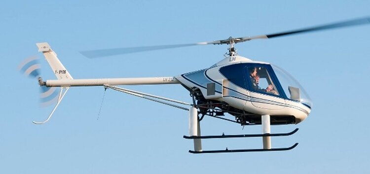 The LCA LH 212 Delta is a two-seat Italian piston engine ultralight helicopter first flown in 2010. Though strong similarities between the Delta and another Italian helicopter, the 1989 DF Helicopters DF334, have been noted, it is not clear if there are direct relationships between either the machines or their makers. The Delta made its first flight after eight years of development. The Delta has a standard pod and boom layout, the latter high set, slender and braced with a narrow angle V-form strut pair to its halfway point from bottom of the pod. It has a short span tailplane with small endplate fins raised above the boom on a swept, high aspect ratio fin, forming a T-tail. The tail rotor, mounted on the starboard side of the boom, has its two blades protected from ground strikes by a long, curved tubular bumper. The pod seats two side-by-side behind a full clear forward transparency. Its skin is carbon fibre over a titanium alloy tube frame. Tandem controls are fitted, with two sets of anti-torque pedals and a T-shaped cyclic control centrally mounted on a console; the single collective pitch lever is placed between the seats. A governor sets the throttle in the absence of pilot input and trim is applied electrically. Small baggage can be stored in under seat lockers. Cabin access is through forward hinged doors in each side. A 84.5 kW (113 hp) Rotax 914 turbocharged, liquid cooled, flat four piston engine with narrow rectangular cheek radiators is mounted behind the seats and partly exposed at the rear, driving a two blade main rotor. The helicopter lands on skids, transversely braced by a pair of airfoil section struts and positioned below the pod on two pairs of similar outward leaning struts, producing a skid track of 1.585 m (5 ft 2 in). The first flight was in 2010 and marketing began in September 2011 at the Blois international ultra light show. A year later eleven flyaway examples had been built. A kit build version is planned. Number built: 11 by September 2012.
 -
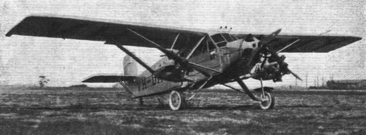 The Lasco Lascondor (also frequently known by the misspelling "Lasconder") was a 1930s Australian 8-seat passenger and mail carrier aircraft built by the Larkin Aircraft Supply Company (Lasco) at Coode Island, Victoria. It is claimed to be the first multi-engined aircraft designed and built in the Southern Hemisphere. Development of the Lascondor began in June 1928, concurrently with the company's Lascoter; the two aircraft had 90% commonality of structural parts. Like the Lascoter the Lascondor was a high-wing monoplane with a tubular steel structure, featuring a tailwheel undercarriage and a fully enclosed cabin for the passengers and the pilot. A major change was the Lascondor's three Armstrong Siddeley Mongoose engines instead of the Lascoter's single more powerful Siddeley Puma engine. The Lascondor also had greater fuel capacity and a slightly longer fuselage with a redesigned cabin to accommodate an extra row of seats. In addition, while the Lascoter had two sets of flying controls in the cockpit the Lascondor had only one to allow for another passenger seat, giving an overall capacity of seven passengers and one pilot. The only available photo of the Lascondor.
 -
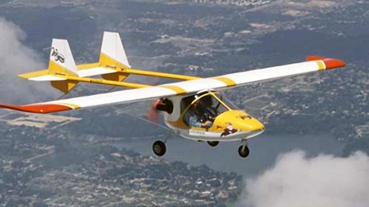
The Laron Wizard is an American homebuilt aircraft produced by Laron Aviation Tech of Borger, Texas. When it was available the aircraft was supplied as a kit for amateur construction. The Wizard features a strut-braced high-wing, a twin-boom tail layout, a two-seats-in-side-by-side configuration enclosed cockpit, fixed tricycle landing gear, with a tail skid, and a single engine in pusher configuration. The aircraft is made from a combination of bolted-together aluminum tubing and fiberglass, with its flying surfaces covered doped aircraft fabric. Its 30.50 ft (9.3 m) span wing, mounts flaps and has a wing area of 140.0 sq ft (13.01 m²). The wing is supported by a single lift strut and jury strut per side. The acceptable power range is 64 to 80 hp (48 to 60 kW) and the standard engines used are the 64 hp (48 kW) Rotax 582, the 74 hp (55 kW) Rotax 618 or the 65 hp (48 kW) Hirth 2706 two stroke powerplants or the 80 hp (60 kW) Rotax 912UL four stroke engine. With the Rotax 582 engine the Wizard has a typical empty weight of 462 lb (210 kg) and a gross weight of 925 lb (420 kg), giving a useful load of 463 lb (210 kg). With full fuel of 10 U.S. gallons (38 L; 8.3 imp gal) the payload for pilot, passengers and baggage is 403 lb (183 kg). The manufacturer estimated the construction time from the supplied kit as 450 hours. By 1998 the company reported that 240 kits had been sold and 220 aircraft were completed and flying.Despite this, a search of most major aircraft photo sites, including jetphotos.com, airliners.net and airport-data.net. only one example could be found on the Russian site airwar2.ru. The image is shown below-
-
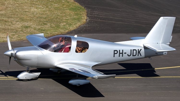
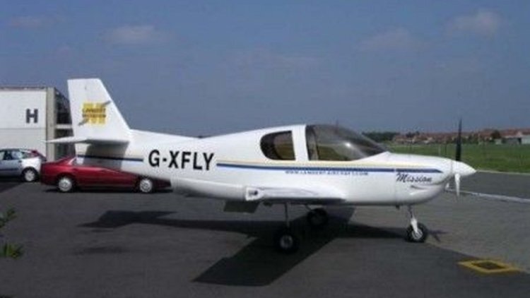
The Lambert Mission 212 is a conventionally laid out low-wing, fixed undercarriage, single-engine, four-seat kit built aircraft designed in the UK by a Belgian college student. Kits are manufactured in Belgium. The M212 has had an unusually long gestation time. It was designed in 1992 by Filip Lambert, then a student at the College of Aeronautics, Cranfield, and was selected as one of three winners of the Royal Aeronautical Society Light Aircraft Competition in 1995. Construction of the M212-100 prototype began in 1996. This aircraft was registered in the UK in 2000 and was displayed, complete apart from some engine and fuel supply systems, at the Popular Flying Association (PFA) Rally held at Cranfield in June 2002. The first flight, delayed by another two years, took place on 13 April 2004 at Cranfield with Roger Bailey as pilot. The M212 is an all-composite aircraft with 95% of its weight in pre-pregs. The wing has two main spars plus an auxiliary one, all formed from glass and carbon fibre in epoxy resin. In plan the wing is gently straight tapered, with most sweep on the trailing edge and with turned up wingtips. It has 5° of dihedral and 2° of washout. Electrically actuated single slot flaps are fitted. Fin and rudder are swept, with a small dorsal fin; the rudder is horn-balanced. The tailplane is rectangular and set a little above the fuselage, carrying inset elevators. The fuselage is a monocoque construction, tapering strongly to the rear. The cockpit seats four in two rows with dual controls in front, covered by a forward-hinged, single-piece canopy. There are two side windows for the rear seat passengers. The M212 has a fixed tricycle undercarriage, the mainwheels mounted on forward-leaning cantilever legs in narrow chord fairings, attached to the fuselage. The mainwheels have brakes and the nosewheel is steerable. Only 2 examples were built. More details here.
-
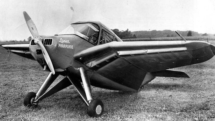
The 1958 Lanier Paraplane Commuter 110 or 110 Paraplane Commuter PL-8 was one of the last designs stemming from Edward H. Lanier's 1930s patents, and aircraft incorporating apertures in the upper surfaces, which claimed to give benefits in safety, lift and STOL ability. In the early 1930s Edward H. Lanier published six US patents concerned with increased aircraft lift and stability, minimising the stall, sideslip and spin. This was to be achieved through vacuum chamber ("Vacua-cells"), initially in the upper fuselage but later in the upper wing, where the reduced pressure established by airflow over a curved surface would act on the lower surface inside the cell, providing lift. The second patent suggests that the cell should contain angled spanwise slats to prevent air entering them at low speeds and that these should be adjustable so that the cells could be closed when required. The earlier patents stress stability improvements; claims of enhanced lift begin with the fourth patent. Five Lanier Vacuaplanes were built in the 1930s, followed by three Paraplanes from about 1948, before the Paraplane Commuter 110 which first flew in 1958. The Commuter 110 had a wing area of 111 sq ft (10.3 m²), large for its 20 ft 7 in (6.28 m) span, and controllable air entrance slots ("Vacua-Jets") under the lower surface near its leading edge, passing air to the upper surface for boundary layer control. Other details of the upper surface are scarce but photographs appear to show rear hinged, single-piece slats over Vacua-cells as well as narrow open channels next to the fuselage in the very long wing root fairings. Structurally, the cantilever mid wing had strongly cranked inner sections and was tapered in plan with elliptical wing tips. The outer panels carried control surfaces which operated differentially as ailerons and together as flaps. In addition there were split flaps under the trailing edges of the wing roots. More details here.
-
Two model aero clubs in Melbourne's east that I know of, Knox Model Aero Club on Stud Road, Knoxfield, with three control line circles, and Doncaster Aeromodellers Club on Bulleen Road, Bulleen, with one control line circle and a grass runway for RC models. Both can be searched on Google Maps.