Ross
-
Posts
729 -
Joined
-
Last visited
Content Type
Profiles
Forums
Gallery
Downloads
Blogs
Events
Store
Aircraft
Resources
Tutorials
Articles
Classifieds
Movies
Books
Community Map
Quizzes
Videos Directory
Everything posted by Ross
-
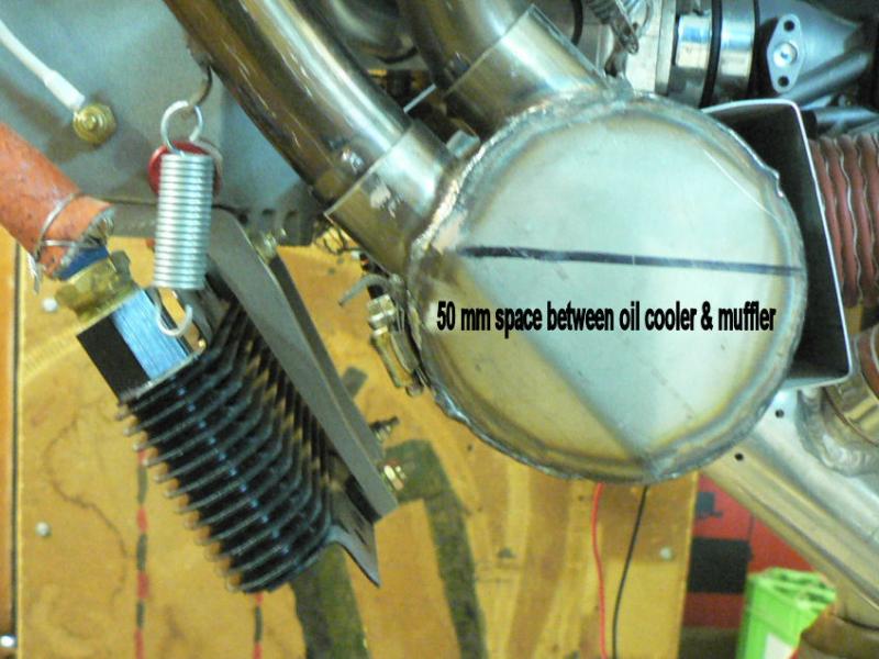
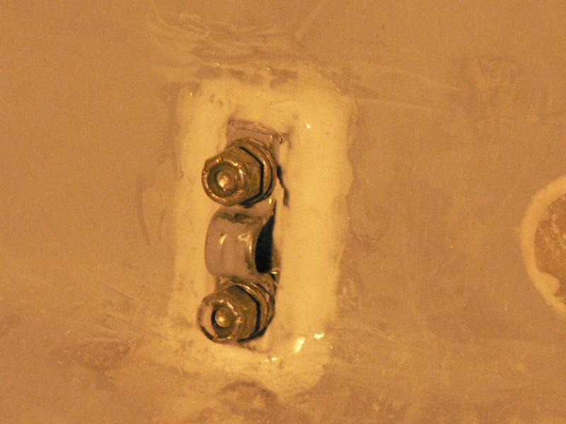
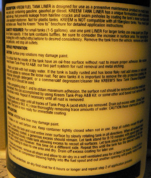
20081214 Hi Jack the oil cooler & muffler are only 50 mm apart with the air inlet side of the cooler only a few mm from the cowl air inlet. It is bounded by a sock of made of Neoprene sheeting pop-rivetted to the opening to keep the incoming air going to the cooler radiator. See attached pic. I can always remove any muffler shielding if it runs too cold. From what I remember of oil theory is that the oil temp maximum generally recommended was the temperature at which the oxidation rate of the oil became unacceptable becoming a major factor in the life of the oil and therefore also a major factor in the life of the motor. For good lubrication, the oil temperature does not have to be near the maximum. When the oil is oxidised it forms very abrasive and corrosive products. The abrasive ones do obvious wearing damage and the corrosive ones should be neutralised by the additives that come the oil but eventually are all used up. The hotter the oil runs the faster all these events take place. When the additives are used up neutralising the corrosive products the corrosion becomes quite dramatic on some parts of the motor particularly some bearing materials. [ATTACH]6934.vB[/ATTACH] When I eventually fly it that will tell me what is going on if my gauges work and I look at them but I do not want a cooked motor on a test flight or shortly after. That would seem easy enough to do without trying going by at least three examples nearby two of which were Jabiru 3000 motors. The third was not a Jabiru. The exhaust spring and lock wire are temporarily removed. Gotta go. A thunder storm. Regards

-
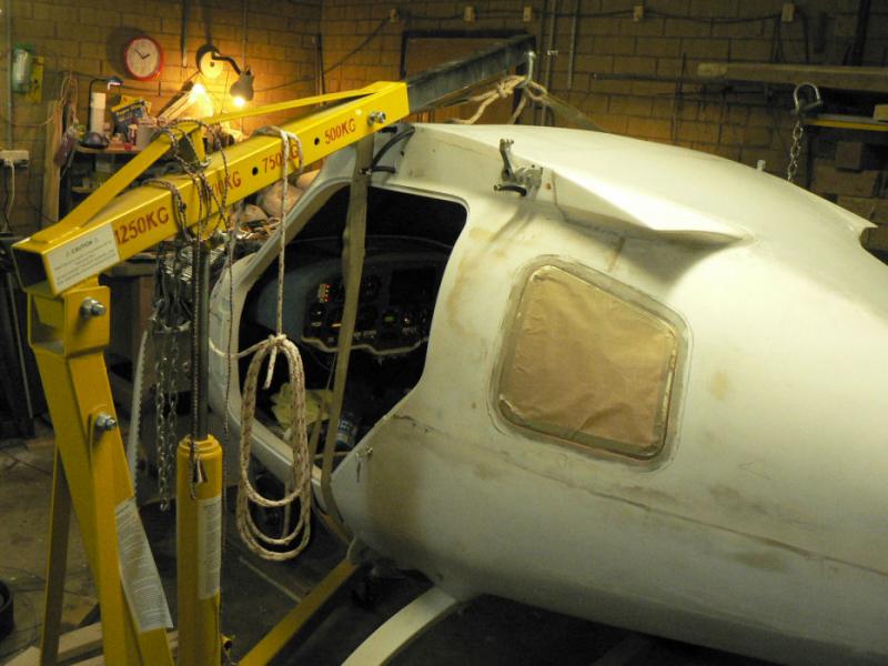
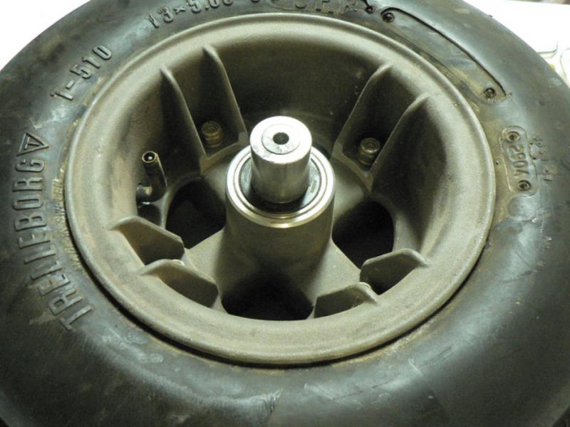
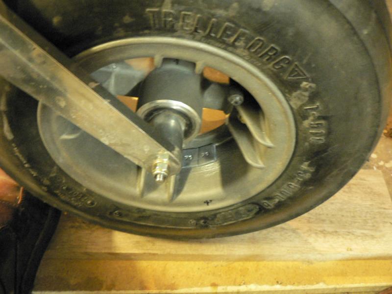
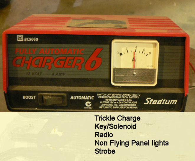
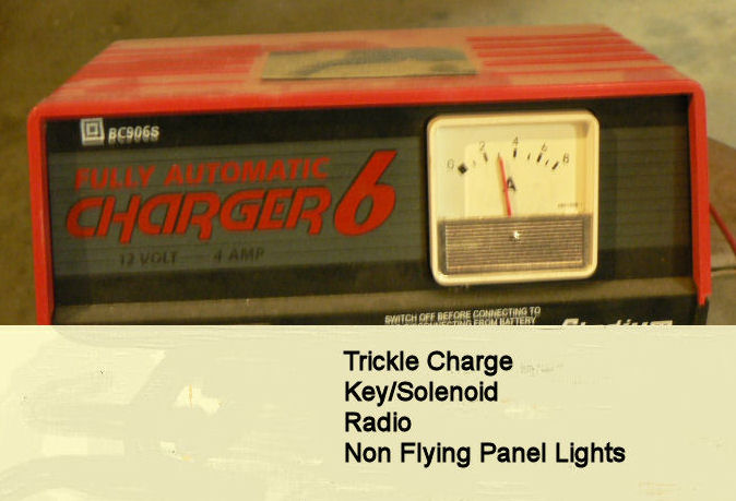
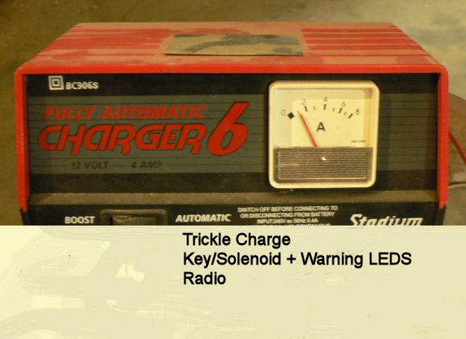
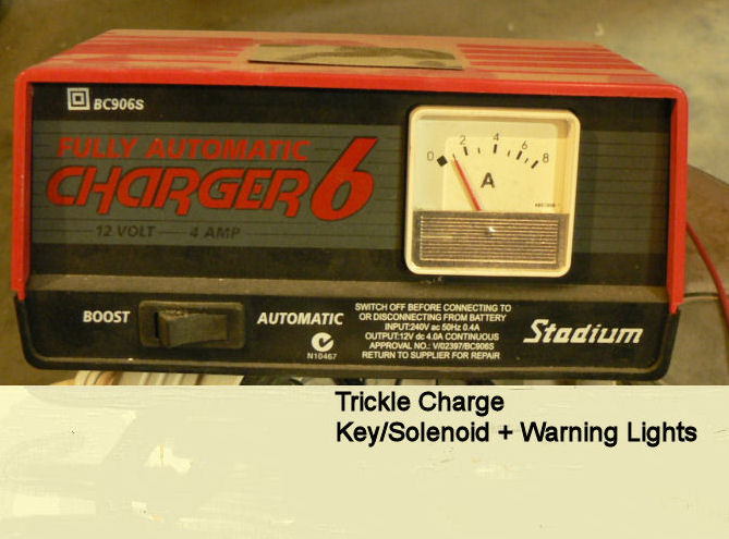
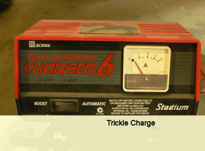
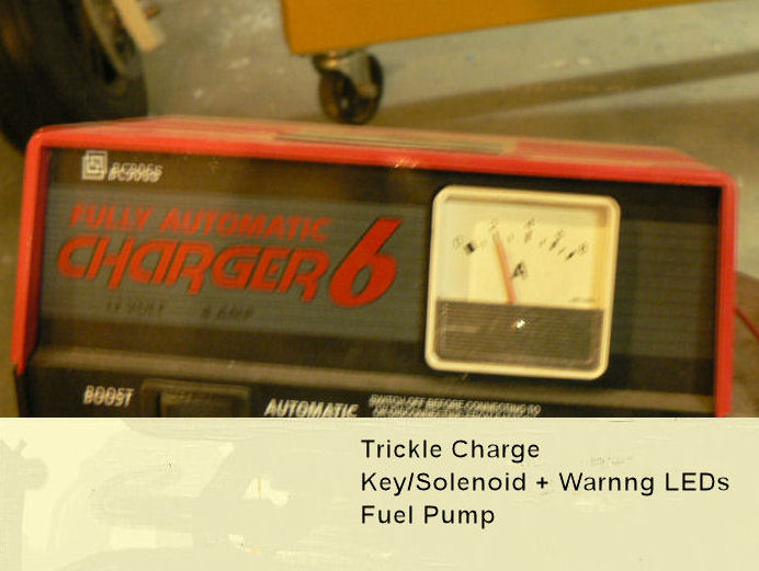
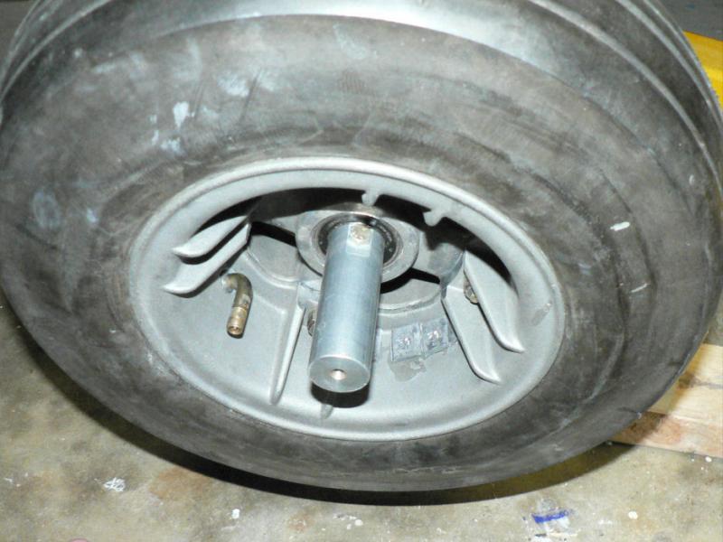
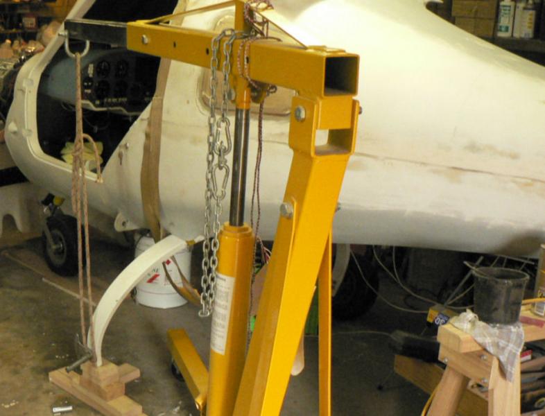
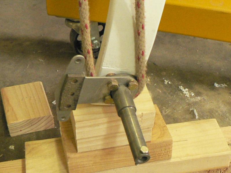
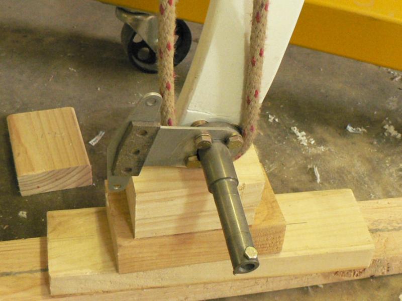
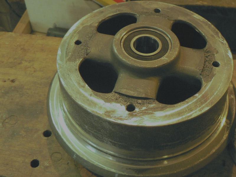
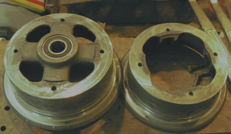
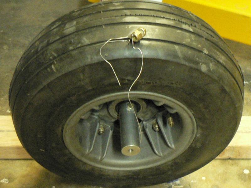
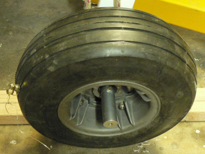
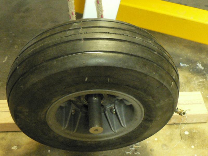
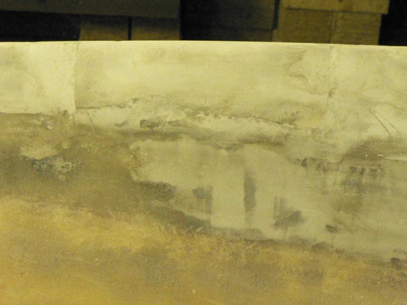
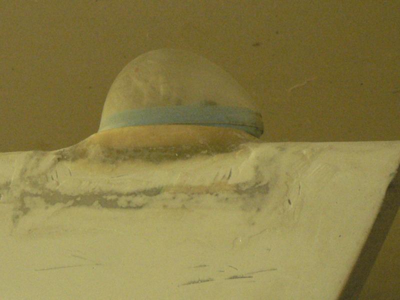
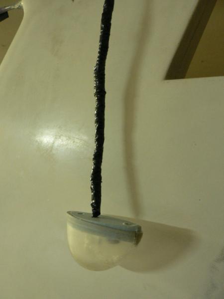
20081213 1. Inserting original foam liner+tube liner into UC Main LH wheel and then balancing wheel after installation. 2. Inserting Foam type liner only into UC front wheel & balancing wheel after installation. 3. Photographed the trickle charger with various loads on the J160 system. .......................................... 1. Lifted LH UC leg to facilitate wheel removal. Removed the LH Main UC wheel, let the air out and split the wheel. Removed the tube and tube liner. Fitted a new foam liner inside the tyre. Dimensions 89 cm x 10 cm x 1 cm Refitted the tube and tube liner. Reassembled the split rim after inserting some air into tube and lined it up inside the rim then tightened up the bolts. Inflated tyre to 30 psi & refitted wheel to UC Removed old balance weights from wheel. Checked wheel balance & fitted new set of weights. ............................................................. 2. Lifted front of A/C with engine hoist and sling under front of A/C. Undid axle bolt through UC fork and front wheel. Let air out of the tyre, Undo the split rim bolts, Prise the tyre down the narrower rim, Split the rims apart, remove the narrower rim taking care not to damage the valve stem, remove the tube from the tyre. Cut a new foam liner. Dimension 89 cm x 10 cm x 1 cm. Fit foam liner inside the tyre. The foam has to be compressed into place as it overlaps a few cm in the tyre to keep it firmly in place. Insert tube back into tyre taking care to place the valve stem in place. Put some air into tyre to prevent pinching the tube when assembling the second split rim. Refit the narrower split rim taking care of the valve stem and careful not to pinch the tube. A G clamp was used to hold some force on the rims to keep the two rims close enough together to get the bolts in and a few threads on the nuts. Once the rims ere close but not tightened the tube was inflated and deflated a few times to get the tube to settle in place and remove wrinkles. Once that is done the tube was inflated with minimal pressure but enough to keep a firm shape on the tube - maybe two or three psi. [ATTACH]6925.vB[/ATTACH][ATTACH]6926.vB[/ATTACH][ATTACH]6927.vB[/ATTACH] The split rim bolts were pulled up tight and then the tyre was inflated to 30 psi. The wheel was refitted to the front UC forks and then the balance was checked. Two weights were needed to achieve an approximate static balance. ............................................................ 3. The A/C battery is permanently on a small charger as I was interested to see what load was on the charger for each item that could be selected from the panel. The pics show the amps reading on charger meter and the items that are switched on at the A/C panel. Excuse the focus. [ATTACH]6928.vB[/ATTACH][ATTACH]6929.vB[/ATTACH][ATTACH]6930.vB[/ATTACH][ATTACH]6931.vB[/ATTACH][ATTACH]6932.vB[/ATTACH][ATTACH]6933.vB[/ATTACH]
-
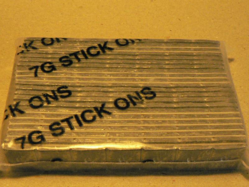
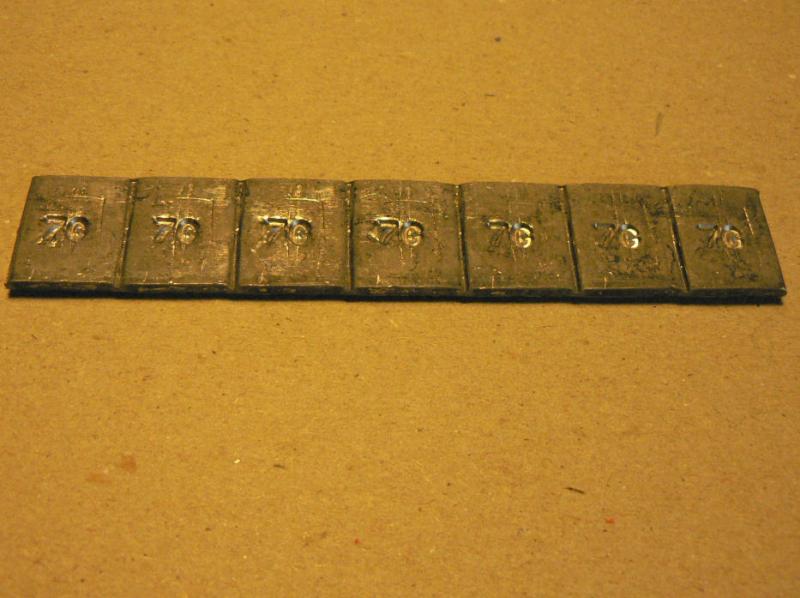
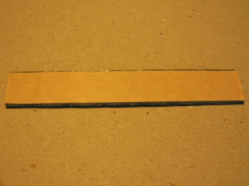
20081212 After the unbalanced wheel yesterday, I got some wheel weights from my tyre shop. I had not noticed this type before but he said he sells a lot to people like model makers etc. They are in strips of seven with divisions that can be easily broken between each seven gram piece. Count them in the pic. They have a self adhesive strip on the back which probably works fine on a smooth or painted surface. Some super glue was used to help them along-maybe a thin smear of araldite might be better. The weights come in a pack of twenty one strips or so which came to $10 for 21 x 7 = one hundred and forty seven of the seven gram weights. I took about 7 photographs of the LH UC wheel with the final set of four seven gram weights on it before the four weights showed up in the photo. One remains and it is not brilliant. I actually went and had another look at the wheel to make sure there were four weights on it. Weights were added until the wheel did not show any preference for a rest position. Once that LH wheel was balanced/finished, the RH UC Main wheel was removed and another tube split and refitted with the original tube inside it. For those who have noticed, yes I forgot to remove the previously fitted foam liner which I had not realised until I saw the other one later on the bench. [ATTACH]6920.vB[/ATTACH][ATTACH]6921.vB[/ATTACH][ATTACH]6922.vB[/ATTACH][ATTACH]6923.vB[/ATTACH][ATTACH]6924.vB[/ATTACH] The tyre and tube combination went on OK so I might reinstall the LH foam liner as well because the imbalance for the LH wheel with the tube liner did not seem to be any different from the original imbalance with the foam liner I had used. It will give an improved puncture protection unless the J160 finds a "Castor Oil Plant". They are like a giant cat head and possibly could pierce the sole of a work boot. Took no pics of the RH assembly aside from the freshly slit tube and the tube to go inside it. Finally woke up that a quick adjusting slide type G Clamp with about a six or eight inch throat is a great aid when assembling the Jabiru split rims. Might need a bigger a/c to carry the tools that might be needed. Remembered to have some air in the tube while assembling the split rim to prevent pinching the tube with the split rims. There was still plenty of powder inside the second tyre and on its original tube. In the morning it will be successful if both tyres are still up. The tube manufacturer suggests to inflate a tube to about 10 psi then let it down and re-inflate to the desired pressure so that the tube will spread into place and hopefully not have any folds or creases in it when normally inflated which can also contribute to an out of balance wheel. The RH UC main wheel bearing had a lot more drag probably due to the seals than the LH UC wheel making it very difficult to check the static balance. A series of small rotations of the wheel were tried which mostly seemed to show little preference for a rest position. It is not nearly as obvious as the freely rotating LH wheel. A bolt used as a spindle was mounted in a large plastic cap off a plastic jar which was mounted in a battery powered 18V drill chuck and spun each tyre as fast as the drill's high speed setting would produce. A larger lid would be better providing the drill does not run out of power. There was no bouncing but it was probably way below 60 odd knots. Driving the tyre on the tyre wall as close to the rim probably doubled the speed but I still did not know what that speed was. The Griffith based LAME can probably dynamic balance wheels as well as props. I shall find out eventually. I think I calculated the RPM of the wheels for a particular ground speed in an earlier posting.
-
Hi Steve I think that I will try and prevent some radiant heat from reaching the oil cooler from the muffler. It is so easy to overheat the engine in that initial climb from the take off where you are rather busy. I will either fully wrap or partially wrap the muffler with exhaust tape or just put a radiation shield between the muffler and the oil cooler like the one that reduces radiant heat getting to the carburettor from the muffler. So I will probably do one of those alternatives before I fly it and then suck it and see. I am still waiting on the muffler tape but have decided to do some more on the tyres again to get them in balance and to replace the liners.
-
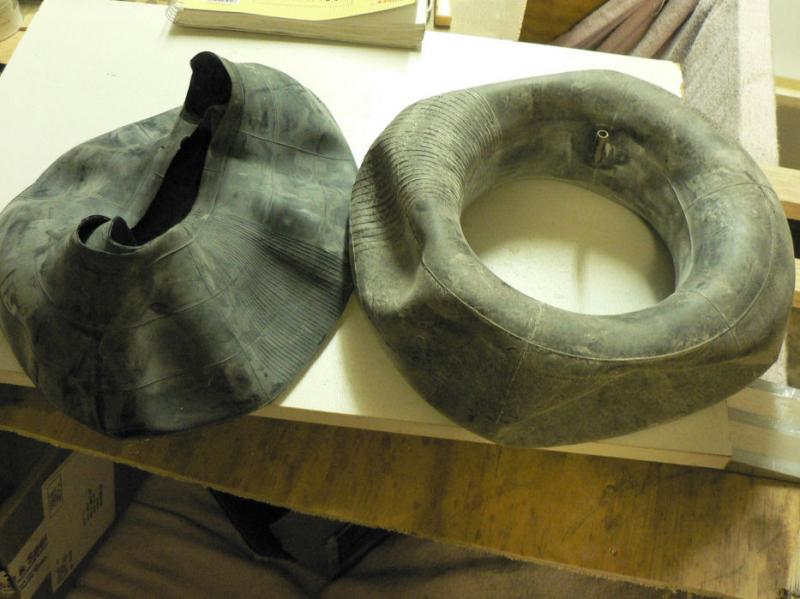
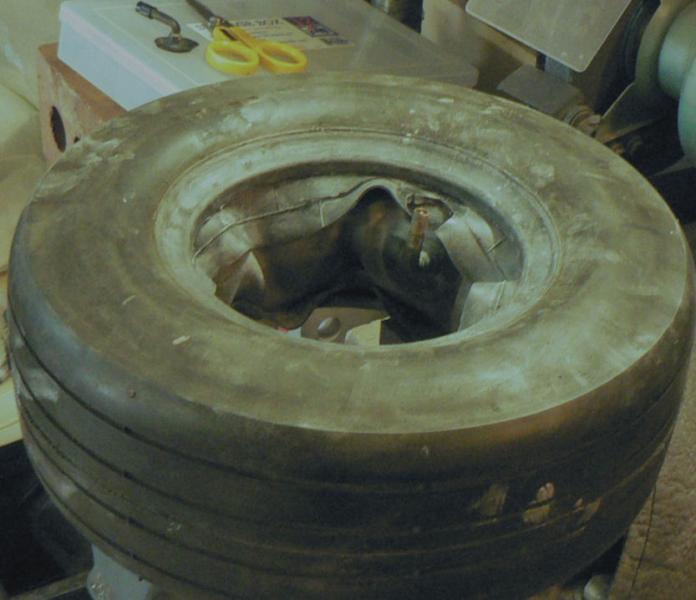
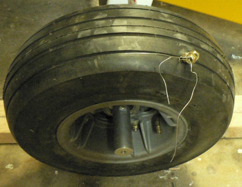
20081211 When the LH Main UC leg was lifted off the floor and the wheel rotated by hand it was apparently a fair way out of static balance so it was removed. The split rim was pulled apart with much difficulty even after taking it down to the local tyre man. Eventually worked out that the two halves of the split rim were an interference fit and so were practically seized together. Would have been very difficult on the edge of an airfield. So the pics show the aluminium anti-seize that I have applied to both halves in the area of the tightest fit before reassembly. Removed the original foam liner that I had fitted and found it to be really squashed up to be fairly thin. I thought this was probably the cause of the imbalance. I had purchased three tubes the same size as the originals 13x5.00-6 at $11-00 ea while at the tyre fitter shop. The packed tubes were folded nicely so that the inside middle of the tube was the position of the fold. So the tube was cut along the fold. The valve stem was also removed. Then inserted the good tube inside the fresh cut tube like an overcoat. One of the locals called it a Nullabor......? Applied a liberal coating of powder in the tyre and also between the tube and freshly cut overcoat tube. Inserted the deflated tube combination back into the tyre. Partially inflated the tube to prevent pinching on assembly. Reassembled the tyre onto each split rim being careful to put on the rim with the valve stem hole last and to ensure that there is no strain on the valve stem and that the bolt holes on the rims line up. Aluminium anti seize applied to matching parts of rims. Bolts were inserted and tightened up carefully. Tyre inflated to full pressure. Fitted the wheel on the UC axle to find that it was still out of balance. The tyre was out of balance enough to move from any position except when the heavy point was lowest. [ATTACH]6908.vB[/ATTACH][ATTACH]6909.vB[/ATTACH][ATTACH]6910.vB[/ATTACH][ATTACH]6911.vB[/ATTACH][ATTACH]6912.vB[/ATTACH] Temporarily tried adding an extra nut to two of the split rim assembly bolts opposite the heavy point. It was not enough so tied a piece of lock wire (marvellous stuff) around the tyre and gradually added nuts 180 degrees around from the heaviest spot. After three nuts were added the wheel could be stopped in any position and would stay there. Adding one more nut would put that point on the bottom of the wheel. [ATTACH]6913.vB[/ATTACH][ATTACH]6914.vB[/ATTACH][ATTACH]6915.vB[/ATTACH][ATTACH]6916.vB[/ATTACH][ATTACH]6917.vB[/ATTACH] Trouble is I might have to take them off to actually take off or land. I'll see if I can get some tyre balancing weights to do the job tomorrow.
-
Volts for your radio I was under the impression that a regulator for a "12 Volt" lead acid type electrical system should produce a maximum voltage of 13.8 volts or was it 13.6 volts. So radios for "12 Volt" systems were designed to put out a full strength signal when run on "14 Volts" DC not 12 volts or 10 volts. A radio radiates energy according to the square of the available voltage. So a drop in voltage say from 13.8 volts down to 10 volts could represent about a 48% drop in radiated power. 13.8 volt down to 12 Volt could cause about a 25% drop in radiated power. Some glider pilots used to add an extra cell to their 12 Volt batteries to keep the voltage in the high end (14 V) longer and above the voltage where a relay in the system might stop working. On the alternator front This might be pertinent depending on what rectifier and regulator is being used but don't ask me which ones are the guilty party as it was a while ago. I don't know if it is still a problem with some set ups! I remember that on some tractors there were some alternator regulator combinations that on starting up a motor would not produce a charge until the motor RPM was around 1600 RPM as indicated by an alternator warning light going out. Remember that when alternators were first fitted to replace generators they generally had to have smaller belt drive pulleys so that they would run a lot faster than the generators that they replaced. On the tractors above, the alternator would continue to charge then even if the motor RPM were dropped back to a normal idling speed of around 1100 RPM or less. So it was normal practice (not necessarily best practice) to run the speed up until the alternator cut in then drop it back and let the motor do a fast idle for a while to warm up. Motors that normally run for most of their time close to their maximum power like tractor and aeroplane engines possibly could run their alternators at a lower speed than the case where engines run a fair bit of their time at low speeds but could also do some duty at high engine speeds. It might extend their life significantly. Regards
-
There are two types of Loctite as far as air is concerned. Anaerobic - sets with a lack of air. Aerobic - sets when air is available. Regards
-
This may not be applicable to you. On an early Jabiru build the builder saw that the output from the alternator were both marked as either positive or negative (I don't recall which) and I am not going out to the garage to see what they are marked in my book. So he decided to join both wires before they made it to the rectifier not realising that they were outputting AC power and I surmise 180 degrees out of phase with one another meaning I surmise again that each wire was alternatively positive and negative but actually opposite to what was happening on the other wire. The result was a burnt out alternator or a change of colour of the coil wiring in the alternator! Regards
-
Hi Jack I am very interested in your results as I near eventually getting my #14 kit J160 into the air. A lot of the engine problems seem to be associated with running the engine too hot so my interest in these posts particularly for the J160. Just a few minutes ago I got an email from AircraftSpruce advising of the consignment of my order for a parcel of exhaust wrapping from the USA! Regards
-
Hi Chris (no offense taken or offered) and others I am a relatively low time powered pilot and will stay that way until I can get my kit J160 into the air. I thought over that observation a number of times before posting it. My primary reason for finally deciding to do so was not to castigate you but I was aware that there was another audience out there not posting but reading the posts and many of those are new and would be pilots with little experience who are reading these posts avidly and looking at all the details and assuming that they are reading the whole story. Hence the brevity of my observation which was not advice one way or the other. They may also be flying in a variety of aeroplanes/weather that may behave quite differently from ones being discussed in the particular posting and so the actions required may be quite different for their scenario. I try in my posts to tell all that I know on the subject which may not be much but which can make them quite tedious to the experienced and also say that I am not an authority on the subject. I still remember a trip back in the 60's as a first time passenger in a small Cessna on a trip to Trangie from Narrandera in the Bishops plane. I still don't know what model it was. We had just climbed a few thousand feet some where near Parkes to clear some thermals I suppose when the pilot noticed the engine was starting to run slightly roughly. I am not sure that I had noticed ( a certificate mechanical engineer no less!). I always thought that the engine and airframe of light planes that I had been anywhere near were all out of balance and made odd noises and vibrated excessively. The pilot soon applied carbie heat for a few minutes and the vibration was cured and did not return after turning off the carbie heat. Now I think I have a better understanding of the process but you could elaborate. I admit that I forget to apply carbie heat periodically when in the circuit and can see a need to have a comprehensive check list that can be readily and easily accessed when flying. It will be high up on my priority list when I start flying my J160. It is also quite difficult to write these posts without offending anybody with no intention of doing so. I just checked to see that so far there have been 596 observations of this subject and very few of those have made any response all though that number would probably include the people who posted as well as each of their editing sessions. Regards
-
I presume insulating anything to do with exhaust gases must reduce the heat loss from the exhaust gases into the steel of the exhaust header pipes or the exhaust muffler and then into the air and/or the other metal parts under the cowl by way of conduction and/or radiation. To continue evaporation of the fuel in the venturi of the carburettor, it needs heat from from the incoming air and the surrounding air and metal etc otherwise it will get colder and colder. If part of the heat supply is removed by insulating the muffler or the exhaust header pipes this could cause the fuel air mix to now fall below the freezing point of water where it did not previously get that cold. If the relative humidity is high enough so that water will condense out of the incoming air it may possibly freeze up in the carburettor throat causing the motor to stop. It might not have stopped if it were in a normal throttle position. The minimal throttle setting aggravates the trend for the carburettor to ice up. I think climbing up past cloud base could result in carburettor ice as the air gets more humid as you climb towards cloud base also depending on air temperatures etc. Yet above cloud tops the risk of carb ice is probably less until you start to descend again.
-
There does not seem to be any mention of "carburettor heat" in this discussion especially with long approaches under minimal power!
-
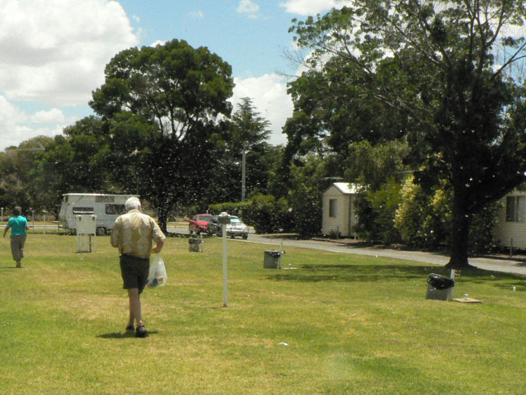
20081206 Scraped and rubbed down the closed in access holes in the top of the rib leading to the vertical stabiliser as well as the strobe cut out and around the aft set of rudder cable anchor bolts. [ATTACH]6887.vB[/ATTACH][ATTACH]6888.vB[/ATTACH][ATTACH]6889.vB[/ATTACH][ATTACH]6890.vB[/ATTACH] The photos show that some more filling and rubbing is still needed! We also had some visitors for the last couple of days who stayed at the Leeton Caravan Park. See included pic showing the grasshoppers rising up from the lawn as we walked from the barbecue area back to their caravan. [ATTACH]6891.vB[/ATTACH] Richard has his head down because of the rising grasshoppers off the lawn. The grasshoppers can be seen as white flashes against the background of the darker trees. Richard and I managed to get 1.1 hours in Wally's J230 at Narrandera on Friday morning. Even though we had taken off at about 9:45 am, the thermal activity was pretty severe despite the whole area having been completely overcast about fifteen minutes before the flight.
-
Yes I'm with you now. I must have been half asleep or just plain dumb. The air going through the motor cooling system for oil cooler and cylinders etc has to put heat into that air. This increased heat content of that air will cause it to expand and/or increase the pressure. Increasing the pressure is not acceptable as it will reduce the flow rate of incoming air and therefore the capacity of the air to remove heat. So it has to be allowed to expand by increasing the exit hole cross sectional area making sure that the shape of that exit does not cause exit problems as well. Some of the heat load could be removed by insulating the exhaust header pipes or the muffler (thus sending more of the the heat out of the cowl area via the exhaust pipes rather than in the cooling air) providing that does not also cause problems as pointed out in earlierr posts on some Jabs by causing excessive carbie ice or reducing engine oil temperature too much. A kit J170 at Mildura suffered excessive oil cooling so the owner mounted a butterfly flap in the mouth of the oil cooler air inlet so that he could adjust it in flight.
-
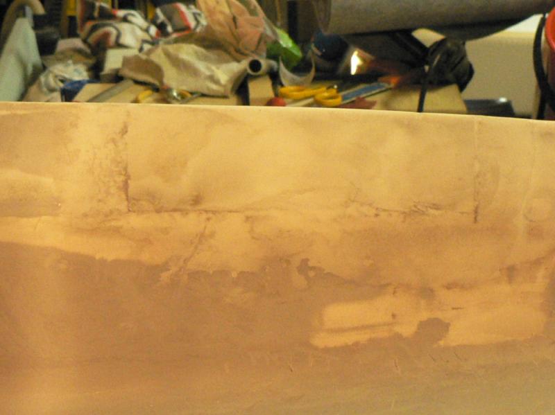
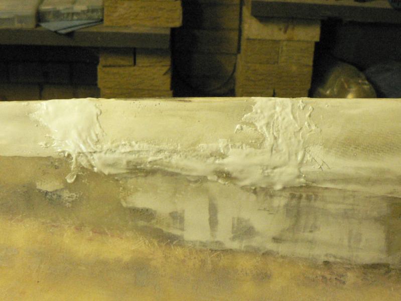
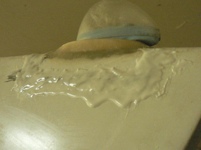
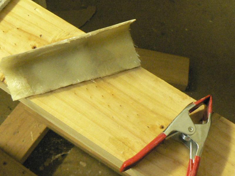
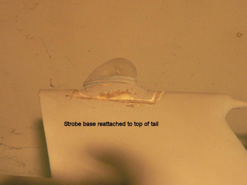
20081202 Despite the dates on the pics this work was done yesterday but not recorded then due to some unexpected interruptions. Finished off sealing the hole in the top of the rib going to the vertical stabiliser and the join around the probe base. Added another couple of layers of fibreglass over the top access hole made on the top of the cable space where the ducting was installed. Made up some flock to do the cover join on the rib using plenty of flock on the fibreglass strips that were already epoxied in place along each side and the top of both V shaped ends of the access hole. Once that was reasonably cured enough to not move, used some more epoxy to make up a small batch of epoxied microballs. This microball epoxy was applied over the top of the join locations for the V shaped cover as well as the join area for the area under the strobe mounting on the top of the vertical stabiliser. [ATTACH]6883.vB[/ATTACH][ATTACH]6884.vB[/ATTACH] It could have been smoothed up more before it cured and some of the excess removed but I was unavoidably called away. It looks pretty messy at this stage but is easy to dress up and get it smooth once it has fully cured. 20081203 Helped to test fit the tail group on Warren's Sonex mostly by lifting and steadying parts as well as checking the movement angles for the rudder. Some minor filing had to be done to ensure clearances for the elevator control and minor adjustments for the elevator stop and some minor filing of the skin in a number of places around the tail group. He has done a remarkable job on the Sonex so far.
-
I was very interested to see a continuous plot of temperature and wind speed during a gliding competition recorded at Brobenah (Leeton) some years ago. About all I recall was seeing the temperature plot varying up and down by about one or two degrees about every five or six minutes or so as did the wind speed over many hours once the thermal activity had started. These wind speed and temperature changes were coinciding with the passage of numerous small thermals across the airfield. The average airspeed at the time was perhaps in the order of about 4 knots.
-
Hi Captain I think I might have seen your dog sitting on a box North of Gundagai waiting for the diurnal wind change when his sail plane driver master usually turns up very late in the afternoon. Regards
-
A local LAME strongly suggested to me to keep my J160 2200 motor on run-in oil for at least 50 hours. It is a 2200 non hydraulic motor engine number #22A 1906. I will see what happens eventually.
-
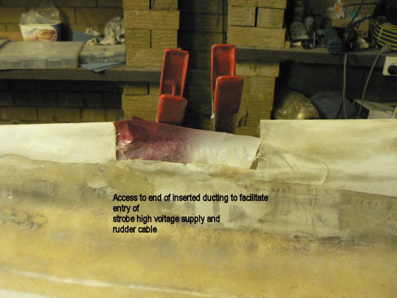
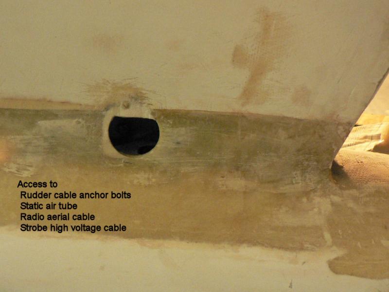
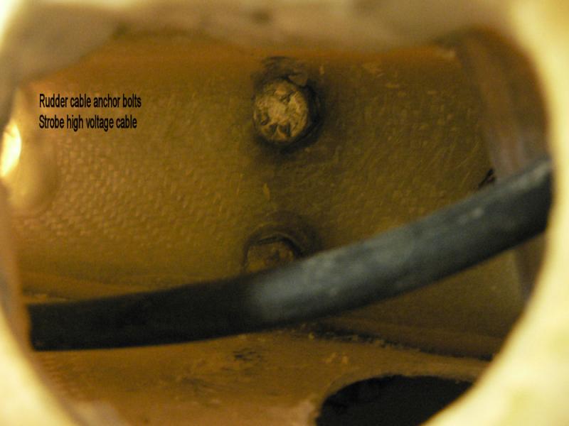
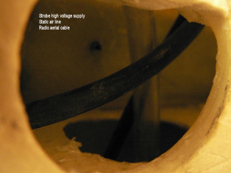
20081201 Strobe Noise I think we need digital radios in our aircraft. Trying the radio again it was apparent that on receiving relatively weak signals the radio seems to have an automatic gain control that kicks in to amplify weak signals and any interference that is near or overlapping the selected frequency bringing up the strobe interference again. Possibly the radio could be adjusted to reduce this interference. I think the adjustment has the ability to narrow the range of the selected frequency but I am no radio expert. It also appears that the interference from the strobe can drift/change depending on how long the radio has been running. Time for me to move along and leave it to the experts! Closing the access holes This afternoon, started closing up the access holes that were made to insert the tubing used to facilitate running the high voltage line to the strobe and the rudder cable to the slot on the port side. The hole in the top of the rib leading to the vertical stabiliser had the tube coming up through a long slot from inside the fuselage into the space along the top of the fuselage. So the entering tube was bedded in with a couple of layers of fibreglass and a layer of epoxy-flock on top of that from each side of the slotted hole. Above that cable space, the next access hole was covered with three layers of fibreglass and will have some more layers tomorrow before the final V shaped cover is replaced over the final access hole on the top of the rib. Some fibreglass was epoxied along the edge of the top/final access hole to make a better join for the final V shaped cover when it is fitted. This will have some more laid in there tomorrow to improve the joint. The V shaped cover had a couple of layers of fibreglass laid inside it to reinforce it. The port side inspection/access hole to the rudder cable anchor bolts, which are epoxied in place at the rudder end, can be seen and accessed through the inspection/access hole near the rear of the vertical stabiliser as well as the static air line and the radio aerial wire. The tail end of the rudder cable is not seen here because it would normally exit the fuselage via a slot on the starboard side before reaching this access hole. [ATTACH]6870.vB[/ATTACH][ATTACH]6871.vB[/ATTACH][ATTACH]6872.vB[/ATTACH][ATTACH]6873.vB[/ATTACH][ATTACH]6874.vB[/ATTACH][ATTACH]6875.vB[/ATTACH] The fibreglass base where the strobe is to be attached on top of the vertical stabiliser was epoxied in place and allowed to cure. It will require some more filling and smoothing around that area.
-
The whole formula is P1.V1/T1 = P2.V2/T2 where the full stop indicates multiplication and the / indicates division. P1 indicates the starting Pressure V1 indicates the starting volume T1 indicates the starting temp in degrees Kelvin. Kelvin degrees = (degrees Celcius +273) etc etc So it all depends where you want to start the calculations because the finished gas mix out the exhaust pipe is not the same material as what entered the air intake and the formula above assumes that no material has been added or subtracted or changed composition from the original compounds by chemical action like burning fuel. That is as far as I want to go in the discussion! (in other words that's all I know) Regards
-
When a local engineering shop was about to weld the pipe socket to the exhaust header pipe of my Jabiru J160 serial #14 to fit an exhaust temp probe as supplied by the Jabiru factory the engineering shop thought that it was not manufactured in stainless steel (the pipes are a dull brownish colour). They thought that it was Titanium!! Maybe I should find some one else to do that kind of work! So I rang Rod Stiff at Jabiru who verified that the exhaust header pipes were definitely stainless steel. Regards
-

fibreglass fuel tank construction info
Ross replied to robinsm's topic in Aircraft Building and Design Discussion
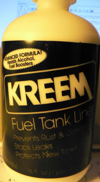
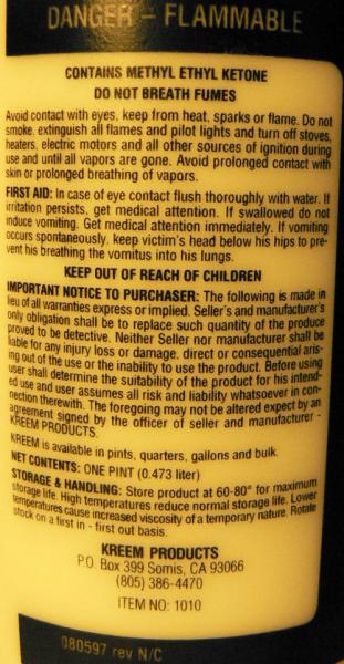
Hi Bob Apparently Jabiru's original fibreglass tanks were lined with a sloshing material that was not proof against any fuel containing alcohols such as ethanol. It was OK for Avgas. Their newest tanks I am led to believe are sloshed with "Kreem" supplied in approximately half litre bottles at about $58 per bottle as of May 2008. Acetone is used as a thinner with this material to aid application. [ATTACH]6858.vB[/ATTACH][ATTACH]6859.vB[/ATTACH][ATTACH]6860.vB[/ATTACH] According to Dan Mulder at Jabiru "Kreem" is compatible with ethanol and all petroleum fuels.
-
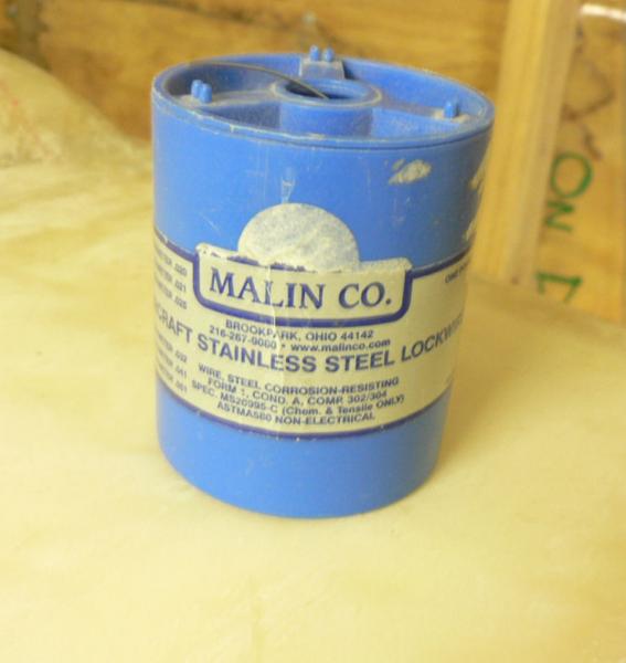
20081129 Hi Linda thanks. I had troubles with my rudder the first of which was because the fuselage was marked incorrectly for the cable holes and no actual hole through the fuselage into the cabin for the cable. Nor could I get full required movement due to the non hinge side bottoming inside the vertical stabiliser when full right rudder was applied with the complication that the dipole aerial is glued in at that point. Perhaps the aerial could have been put right in the right hand corner of the vertical stabiliser but I did not think of that until afterwards and it may not have been far enough anyway to give full movement. So I drilled out the hinge rivets on the stabiliser side then "Araldited" an extension strip onto the hinge positions to extend them further aft and then drilled new holes and refitted the hinges. The top rudder hinge could not be put in the correct position unless it was mounted with the rudder hinge pin going in upside down which makes it marginally less safe. The instructions for the rudder offset were unclear with at least two alternative interpretations possible and not enough adjustment in the cable to fix it if the wrong interpretation were taken. I think I eventually decided that the rudder maximum deflection was to be each way starting from the offset position of the rudder. From memory, the adjustable length in the rudder cable is not as stated in the instructions making the placement more critical. I think all these problems may have been resolved more easily with a more experienced builder. The new construction manual and probably some better quality control also probably helps on the later kits. Our J160 kit was #14. The Jabiru parcel with some Resin & Hardner plus the "Kreem" sloshing liquid arrived yesterday. I also ordered some exhaust wrap from Aircraft Spruce to reduce the heat load under the cowl area for wrapping the muffler and/or the exhaust header pipes. See other posts on this subject under Jabiru users group. There are a number of possibilities of different materials available mentioned on the web site in those posts. A piece of Heat Shield about 100 mm x 300 mm, Aluminium with a layer of very pliable sticky goo on it obtained from the local Holden dealer, was found to be highly inflammable when I applied an LPG gas torch to it. It readily caught fire then easily maintained a long flame (about 20 cm) with intense black smoke and dripping hot burning melted plastic like goo on the ground. Radio and Strobe power lead I think the noise in the radio from the strobe was cured this afternoon at least while the A/C was parked in the garage without the engine running. I used some stainless steel lock wire to shield the last few unshielded cm in the strobe power cable. The stainless was wrapped around the new shielded power cable starting below the join and continued right up to the unshielded base of the strobe then continued back down over and past the cable join again. The SS wire was connected to the shield on the new power cable by scraping some rubber off the shield, inserting the SS lock wire between the rubber and the shield which also appears to be SS and wrapping it around the shield wire. It was not soldered. The whole was then wrapped in insulating tape before trying out the radio. I think my wrapping gap between successive rounds of the SS lock wire was about one or two mm but was enhanced by returning back over the first layer with a second layer. The radio was tried with the strobe back on top of the tail and the squelch knob hardly needed moving from it's no strobe squelched position with no interference to completely suppress all strobe noise from the radio while it was scanning all the 25 stored frequencies with the strobe then operating normally. Fantastic at last!:thumb_up: [ATTACH]6849.vB[/ATTACH][ATTACH]6850.vB[/ATTACH] So I deduce from this that most of the noise came from the power lead in the last unshielded 15 to 20 cm of the power lead right up to the base of the strobe with the strobe itself apparently irrelevant. I gather also from some reading, maybe irrelevant, that if the power lead core wires were twisted for their full length including the last bit into the strobe the interference might also have been suppressed. The next step I had thought of was to mount the probe on a flat plate immediately below the strobe to shield the aerial and to connect that plate to the shield as well but it was so good that I did not even try that.
-
Hi Jack. I am very interested in your exhaust wrap ideas as the Jab engines seem prone to damage from even short bouts of overheating so anything that can keep the engine temps down a bit including oil temp would have to be a plus in our weather conditions. I have already purchased the modified bottom cowl to extract more air from the engine bay and will probably fit the extended lip to extract more air again. So what material are you using for your exhaust wrap and where can you get it? Regards
-
For interest's sake here are some Coefficients of heat Transmission in BTUs per second through metals 1 inch thick per square inch of surface for a temperature difference of 1 degree Fahrenheit. The bigger the number the greater will be the temperature on the cold side as more heat is being transmitted. Aluminium 0.00203 Brass, yellow 0.00142 Copper 0.00404 Iron 0.00089 Steel, soft 0.00062 Steel, hard 0.00034 Best of the list to give the least heat/temperature on the cold side. So to protect the fibreglass with only the choice above Copper would be the worst and hard steel would be the best for the same thickness of metal to give the lowest temperature on the cold side by a factor of almost 12 times and almost 6 times for aluminium. Of course a non metal would have far better insulating properties but it needs to be heat and temperature tolerant. Sourced from my old engineer's reference bible the "Machinery's Handbook" 16th Edition 1963 p.1923. It cost me Seven pounds and five shillings in about 1964.