Ross
-
Posts
729 -
Joined
-
Last visited
Content Type
Profiles
Forums
Gallery
Downloads
Blogs
Events
Store
Aircraft
Resources
Tutorials
Articles
Classifieds
Movies
Books
Community Map
Quizzes
Videos Directory
Everything posted by Ross
-
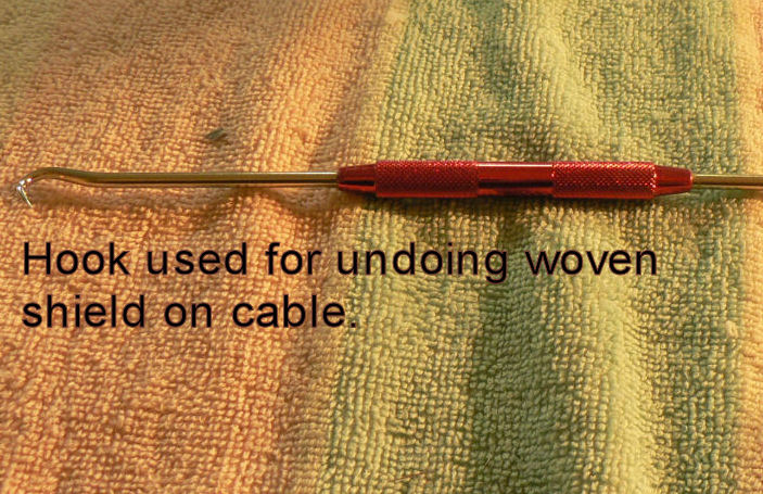
20081120 Hi Linda, Brian & Biggles I would be worried if anybody was using my experiences as a guide as what to do or what to do next. If I ever built another one I am sure that my experience on this build would supply me with many examples of what not to do! How about you guys inserting some comments or suggestions based on your experience or advice from others - it feels pretty lonely out here! As to my activity or rather the lack of it my health has been a bit off with bad chest colds etc aggravated by a former life of working in a number of bad for chest health industries made worse by smoking until I had a heart attack about twelve years ago. However last week on 19th Nov I attended day surgery in Wagga to have a cataract removed from my left eye and a new lens fitted in place of the removed one. That now completes the set. The first few days feels like I had a bit of gravel behind the eyelid but is fairly good now. Now all I have to do is wait for another month for the eye (and the brain) to stabilise after a follow up inspection by the surgeon in Wagga tomorrow before I can get new prescriptions for my reading glasses. That will make it about 27th December before I can try to get the prescription etc. But how great it is now that I don't need glasses for flying or driving and already have got my driving license endorsed back to no glasses required-fantastic. I don't like my chances of getting the prescription and new glasses before February though and my old glasses are quite aggravating to wear now. However I have decided to reline my wing tanks with the latest sloshing solution so that it can cope with all possible fuels including those containing alcohol (ethanol). It can be applied over the top of the existing sloshing material. Dan Mulder at Jabiru says that the contractors doing their tanks use about one litre of "Kreem" per wing tank. You need to do the header tank as well. I will feel better after doing this even if I don't use other fuels as it should seal around the points where the tank filler holes and drain holes in the wing tanks as well as the hole in the header tank for the float switch were installed. I do not know when Jabiru changed to using this sloshing material. I think that it was relatively recently. So I have ordered three 500 ml bottles at approximately $58 each not including freight from Jabiru (that price was in May 2008) and have asked Dan to send me an email explaining the process. He said that some acetone is used to thin the "Kreem" before application. Got an email today dated two days ago announcing that the sloshing liquid should arrive in Leeton tomorrow while I am in Wagga!! Will it get lost before we return from Wagga Wagga tomorrow afternoon? I also occurred to me that if I was to shield the last 100 mm or so of the power supply to the strobe just below the strobe (where I had joined the new cable to the strobe short wiring) by wrapping some steel wire around that power lead and soldering it to the shield cover on the new wire just below it, it might have a large effect on further reducing the strobe noise that gets to the radio. That last bit of power lead to the strobe is only a few cms from the top of the dipole aerial mounted in the back of the vertical stabiliser.
-
My J160 is yet to fly so I have modified the ducts after viewing a number of low time jabs with failing ducts due to excessive heat from the head contact damaging the fibreglass. This is apparent from the colour of the fibreglass at the failure point. I have Araldited strips of stainless steel between the ducts and the heads on the inside of the ducts and drilled them to take the cap screws.. I have used stainless steel in preference to aluminium or copper as it has a substantially lower coefficient of heat conductivity than either of those metals. This should result in a lower temperature on the fibreglass that it is bonded to provided that it is attached inside the duct and not the outside. If the main heat supply is coming from the cap screws it may need an insulating washer under the cap screws.
-
Fasteners The free and free post "Aircraft Spruce & Specialty Co." catalogue has many different fasteners listed with photos and often with explanations of how to use them and in what situation. All the fasteners mentioned in the previous posts are listed and priced. The Spruce catalogue has over 700 pages of aircraft related parts and equipment listed and priced. It is often able to supply Australia from the west coast or east coast of the USA in about a week with certified or uncertified materials and equipment.
-
Strobe radio interference on my J160 kit with Microair I tried replacing the original unshielded cable to the strobe with some 4 core shielded cable from Jaycar for the high voltage supply between the strobe and the strobe power box. The outer shield was earthed/connected to the body of the strobe power box. I also used shielded wire for the low voltage supply from the A/C bus etc to the strobe power box. It was also earthed to the strobe power box. It did make a big difference for most stations to the noise from the strobe but it did not reduce it evenly from all stations or eliminate it completely. That may be quite different once the A/C is flying with the engine going and tuned to the closest transmitter which would usually be the case. I am testing my MICROAIR, an early model now 4 years old, on the ground in the garage at my home home with the scanner going as it would be illegal to transmit until the aircraft is registered. In normal operations I presume the scanner would not be used. The channel that generates the most interference is usually the distress frequency. I have no trouble using the squelch to eliminate the interference on any frequency that I can pick up. I can pick up traffic inbound for Melbourne from the West, Sydney traffic inbound from the West and inbound for Mildura, Griffith, Mt Gambier, Dubbo and Ivanhoe plus plenty of Melbourne centre flight level traffic when there is any sort of weather to contend with. I hear plenty of calls where Melbourne Centre is notifying airline traffic that they are out of radar coverage. For some reception it appears that some background interference is being generated by the transmitting radio or it's wiring arrangement because other transmitters on the same frequency generate no interference noise at all. For different frequencies & (distances??) the amount of squelch required above the background noise with the strobe turned off to having the probe turned on ranges from none extra for some stations to a maximum of about half a turn extra of the squelch knob for the worst of other stations. All these results are with the engine not running which might introduce an extra amount of interference. At Leeton township in my garage (J160), I am probably about 20 NM from the transmitter at Mt Bingar near Griffith for the area frequency for Melbourne centre and the Griffith CTAFR and about the same distance from Narrandera for the CTAF there. After some experimentation I am sure that most of the noise comes from the strobe, not the strobe power box, because of its proximity to the Jabiru Dipole aerial mounted on the back of the vertical stabiliser only about 200 mm away. Even temporarily sitting the strobe on the front of the static probe in front of the vertical stabiliser further away from the aerial reduces the interference noise. I had rung Jabiru about this problem and they seemed reluctant to talk about it. They inferred that replacing the original not shielded high tension leads to the strobe on the tail with shielded cable would probably improve things. They were not in a hurry to supply me with the shielded cable. I was tempted to try mounting the strobe on top of the cabin or to use wing strobes instead which would have increased the cost dramatically and may not have worked anyway going by the first Jab LSA 55 that I flew which has wing strobes. Despite the strobe noise occasionally, the Microair radio is still miles better than the radio in the Piper PA28-140 a/c that I first soloed in at Narromine in about 1971.
-
20081105 I thought that I had a problem with wiring for the passenger side radio and intercom as I could not get any radio reception on that pair of jacks. Maybe I had a cold joint in the solder on one of the jacks or I had cut a wire drilling the holes for the cable ties or I had wired it incorrectly. So I cut all the cable ties anchoring the radio harness behind the seats to the fibreglass cross beam behind the seats and removed the anchor nuts from the jacks so that I could pull them out where I could examine them. I then examined all the wires and the soldered connections to the jacks and the tags that are still attached to the wiring leads. All was in order but not a peep out of the passenger side earphones which worked fine on the pilots side. Then I remembered about the intercom. It has a push button switch to power it up and another switch to select either "ISOL" or "ALL". So I discovered (again) that unless the power is on the Intercom panel (and the radio) and the selector switch is on "ALL" the passenger will hear neither the radio or the pilot via the intercom and will also be unable to talk to the pilot. I cannot tell by the switch position if the power is on or off the intercom and there is no led to indicate power on or off. So I pressed the power switch to power the intercom and moved the selector switch to the "ALL" position. So today I put the jacks back in place and attached the nuts to keep them there and replaced the cable ties to secure the loom behind the seats out of harm's way. Tested the reception and mike again - it still works despite my efforts! I also fitted new seals on the swimming pool sand filter selector valve as well as the guts of the damaged valve with a slightly modified new one. Then spent a few hours removing heaps of gum tree leaves from the bottom of the pool which is full of very green water. Hopefully tomorrow I might get to see the bottom of the pool again. The salt chlorinator was not having much effect on the free chlorine level in the pool by the time I eventually turned it off.
-
Darting off the runway I used to wonder why I was darting off the runway after touching down after a landing. I finally woke up that it only happened when I was landing in a cross wind whether it was in a Jabiru LSA 55, J230c or Wally's Tecnam at Narrandera. But then I am almost always landing in some sort of cross wind even if it only a couple of knots and is almost unnoticeable during the circuit. So if I land in a cross wind from the right I have the A/c banked to the right with left rudder on to keep the a/c lined up on the runway. Once I touch down on a single wheel or two wheels in this condition (if I don't change the rudder deflection) the a/c will immediately swing to the left even if the nose wheel is on the ground because the rudder will now be pushing the tail more into the wind on the right but the mains are anchored on the ground and starting to point to the left in relation to the runway and the nose wheel is also turned to the left. So I needed to reduce left rudder input the moment a main is on the ground but the wind is now trying to push the tail to the left before the front wheel is on the ground so it still needs some rudder to stop it weather cocking into the X-wind. Then I would have it almost neutral once the front wheel touches down otherwise I would be doing a very rapid close examination of the left hand edge of the runway because the rudder pedals are linked to the front wheel steering. The distance from the front wheel to the mains is very short on a Jab so a small rudder movement results in a large change in angular direction once the front wheel is grounded - but the Jab cannot turn as sharply as a castoring front wheel would allow with the aid of individual main brakes. So it makes life much easier if I keep the front wheel off the ground for as long as possible and coarse steer with the rudder then remember that I am fine steering with the front wheel once it drops on the ground and then will probaly need even less rudder pedal input to keep it straight up the runway. This is all very difficult because I cannot see how much rudder I have applied as my feet are not within view. I am going to have to learn all this again once I get my J160 flying as the rudder pedals will feel different at that moment of truth as we touch down in every different x-wind component. I always reckoned that it would be easier to learn X-wind landings if we had a rudder (or front wheel) position indicator on the panel in front of the pilot. I was told recently that there is such an indicator on Boering 747s. I guess the spring loaded rudder centring system on the Jabirus is one approach to this problem - but then I was always reluctant to take my feet off the pedals in the middle of a X-wind landing then without any input from me, relying on the rudder to go to the neutral position which is actually about 5 degrees of right rudder. This might even result in a ground loop if the x-wind is strong enough and leave the two ends of the a/c no longer connected by the fuselage.:black_eye:
-
Another method of making the original self tappers used for making fairings more secure is simply to drill the holes out slightly then mix some flock and epoxy(araldite) and push it into the hole aiming for a bit of a lump on the inside. Normal preparation of sand-papering the area, cleaning it with acetone and applying a thin layer of epoxy before the main job will make the plug more secure. Allow to cure. Re-drill the hole to suit the self tapper. Perhaps use a slightly longer self tapper than the original. I bought extra captive nuts as used for securing the various hinge pins and used them where ever possible instead of self tappers - eg for joining two parts of a fairing.
-
"The US gallon (3.785 411 784 Litres) is divided into four liquid quarts (946.352 946 mL each)"
-
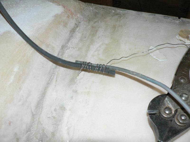
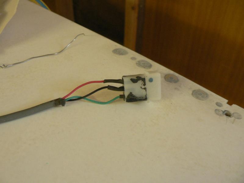
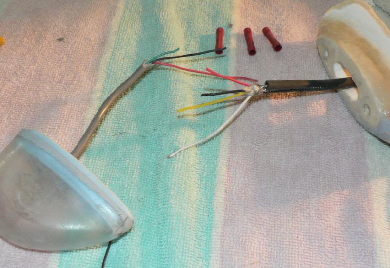
20081025 Not as good as I thought in daylight now compared to last night. Did I have the strobe turned on! A check list s needed for these sorts of tests to make sure all possible sequences and conditions are checked. Changed some of the bullet connectors used yesterday as when heat shrink was used on them applied to cover the insulation on the connector, the subsequent heating also shrunk the insulation (very thick tough heat shrink) already on the bullet connector. So the female half shrank compressing the joint making it impossible to insert the male half of the joiner because it actually also extended past the end of the female bullet connector by about 2 or 3 mm and was even smaller in diameter there. The other problem was that the wire was inserted too far into the bullet joiner before crimping it therefore interfering with the male half when it was inserted. [ATTACH]6744.vB[/ATTACH][ATTACH]6745.vB[/ATTACH] The white lead wire in pic one connected to the outside shield on the cable was turned around a bit to be further away from the multi-pin plug cutting down some static.

-
20081024 Had to go to Wagga today so got some more heat shrink plus some cable joiners. Finished assembling and fitting the shielded 4 core wire from the probe power supply to the strobe mounted in the same as original place on top of the vertical stabiliser. One of the four wires is not used-different colours compared to the original which matched the colours on the strobe and the power supply - so be very careful! I used the matching heat shrink colour on each end of the four shielded cable core wires that were used. Connected the steel shield braid of the new cable to the case of the strobe power supply. I had already used shielded wire from the strobe power supply on the low voltage side to the a/c power supply bus and probe switch. The shield of this wire was connected to the case of the strobe power supply as well. Before installing this shielded cable from the high voltage power supply to the strobe the radio required an extra half turn of the squelch knob to eliminate the strobe associated static on receive. After installing the shielded cable to the strobe on the tail the thresh hold for the strobe static and the background noise is the same. So no additional squelch required on the radio after turning on the strobe. I wonder what will happen after the motor is started. I do not know if it would have generated noise in the transmitted signals before or after fitting the new cable.
-
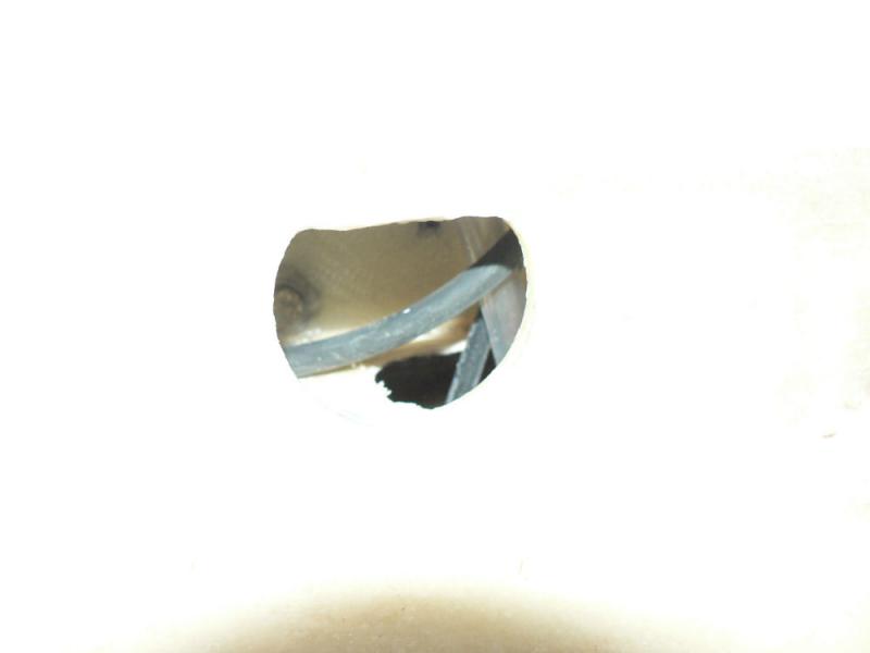
20081023 Some pics covering some of the activity over the last few days. The strobe and cable routing activity seems to be two steps forward one step backwards-trial and errors! [ATTACH]6721.vB[/ATTACH][ATTACH]6722.vB[/ATTACH][ATTACH]6723.vB[/ATTACH][ATTACH]6724.vB[/ATTACH][ATTACH]6725.vB[/ATTACH][ATTACH]6726.vB[/ATTACH][ATTACH]6727.vB[/ATTACH] Pic ! cable has been pushed up to the tail here with a piece of wire from the cabin end. Pic 2 shows hose-replaced later. [ATTACH]6728.vB[/ATTACH][ATTACH]6729.vB[/ATTACH][ATTACH]6730.vB[/ATTACH][ATTACH]6731.vB[/ATTACH][ATTACH]6732.vB[/ATTACH][ATTACH]6733.vB[/ATTACH][ATTACH]6734.vB[/ATTACH] [ATTACH]6735.vB[/ATTACH][ATTACH]6736.vB[/ATTACH][ATTACH]6737.vB[/ATTACH][ATTACH]6738.vB[/ATTACH][ATTACH]6739.vB[/ATTACH][ATTACH]6740.vB[/ATTACH][ATTACH]6741.vB[/ATTACH] Pic 1 shows PVC 25 MM duct tube; Pic 3 & 4 this row, rudder cable has been extracted then pushed back to avoid paint.
-
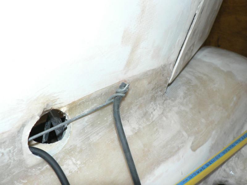
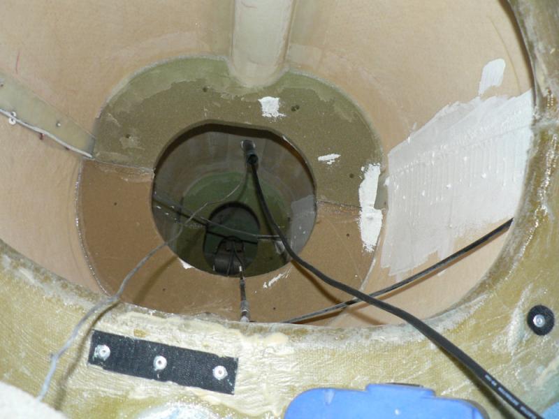
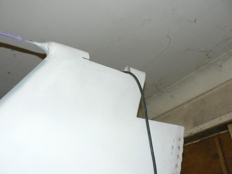
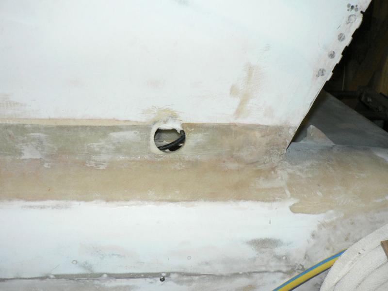
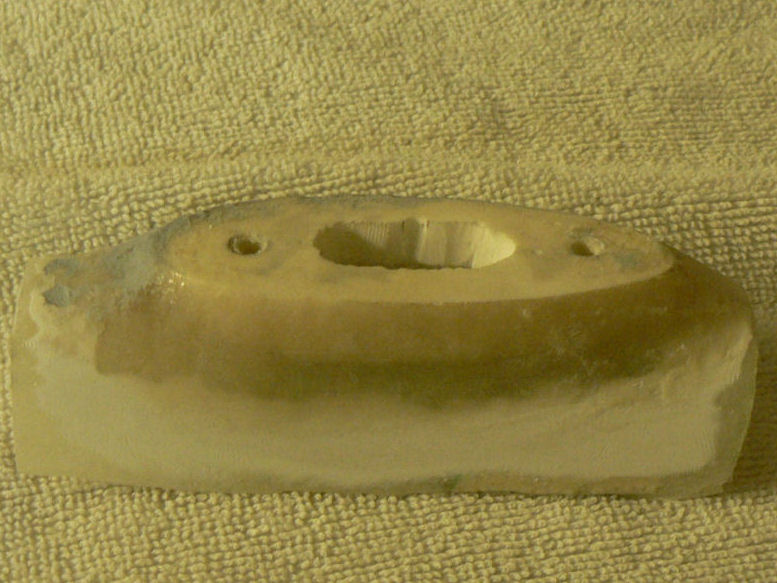
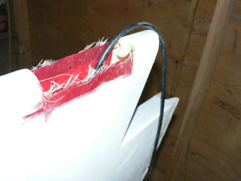
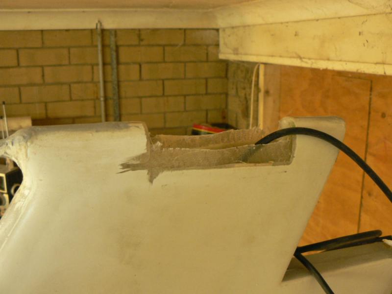
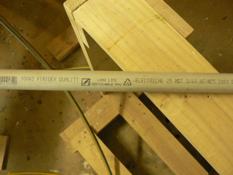
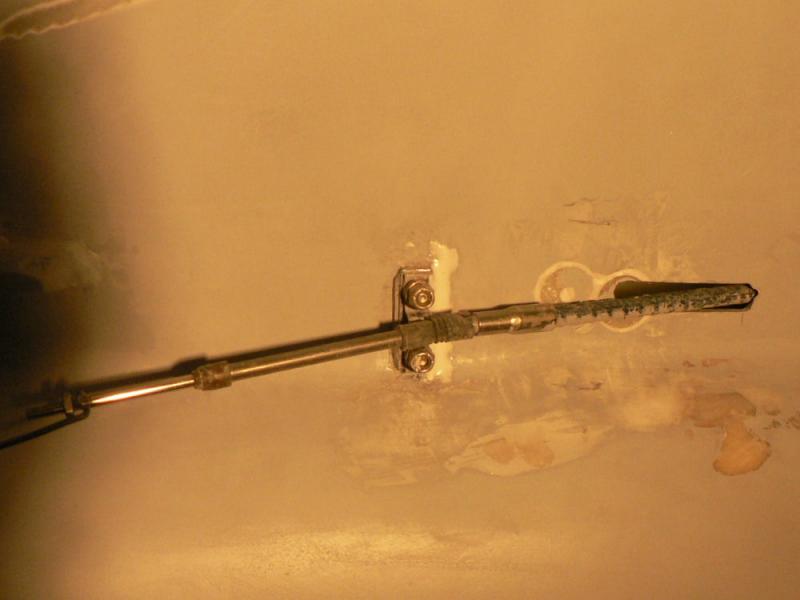
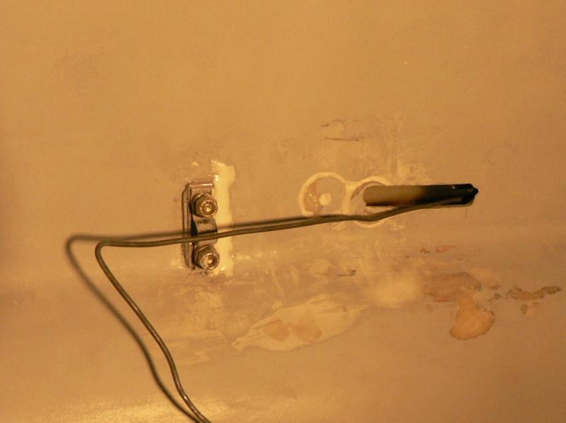
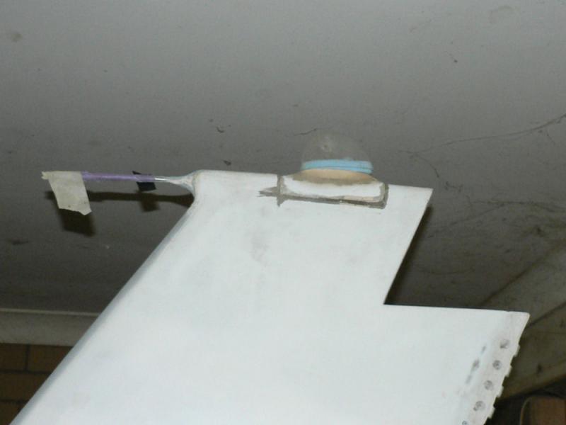
20081014 The strobe was producing a lot of noise in the radio reception and is possibly the reason why some Jabs produce horrible static when transmitting. A reduction of static noise was noticed if the detached powered strobe was temporarily tied to the static probe roughly doubling the distance from the strobe to the top of the dipole aerial. Removed strobe 3 core unshielded cable. Bought 3 core shielded cable locally to try for reducing strobe noise in radio which could be eliminated using a lot of squelch. This cable proved to be unsatisfactory as one of the core wires was not insulated. Ordered some 4 core shielded cable from Jaycar and 4 clamp on style ferrite RF noise suppressors to cover the frequency range of the radio. The core wire in this cable is very light copper instead of a steel like wire in the original cable. It will be easy to replace if necessary. At this stage I managed to damage the strobe globe so also ordered one from Aircraft Spruce with freight by the US Postal Service. $US49.50 plus about $US28 freight became $A121.88 by the time it arrived here yesterday. The cable and ferrite clamps arrived from Jaycar the day before. 20081023 It was apparent that the short piece of 3/4" hose I had inserted to facilitate feeding the rudder cable and the strobe cable was too small in internal diameter and would have been better a bit longer. It made inserting more than one cable very difficult with a high probability of damage. To gain access to the previously fitted 3/4" hose cut a hole in the top of the fuselage above the hole in the bottom of the top roof channel. I removed the hose that was epoxied in place and then replaced it with about 80 cm or 36" of grey 25 mm OD electrical PVC ducting tube. It has an ID of about 21 mm and enough flexibility to be pushed up into the over head channel in the fuselage in the same place as the 3/4" hose was located with the entrance to it being set forward of the nearby whalebone in contrast to the hose entrance which was difficult because it was set about 15 cm aft of the whale bone. So the electrical duct 25 mm OD PVC tubing has a bend in it where it enters the overhead channel. The aft end of the tube was chamfered with a pocket knife inside to make extraction of the rudder cable less likely to catch on the entrance. The aft end of the tube was also chamfered externally to make it easier to push it up into the channel from inside the cabin with my knees on the pilot seat and hanging over the back of the seat. I would love to have a back door in a J160 Kit. The hole for access into the channel where the previous piece of hose entered was extended to allow a fairly flat entrance angle of the tube to prevent it kinking therefore allowing a greater depth of penetration as well and less likely to restrict cabe insertion or extraction. It was also better to have a very gentle bend there to allow the control cable to be fed through the bend without damaging the universal type joint on the end of the cable.
-
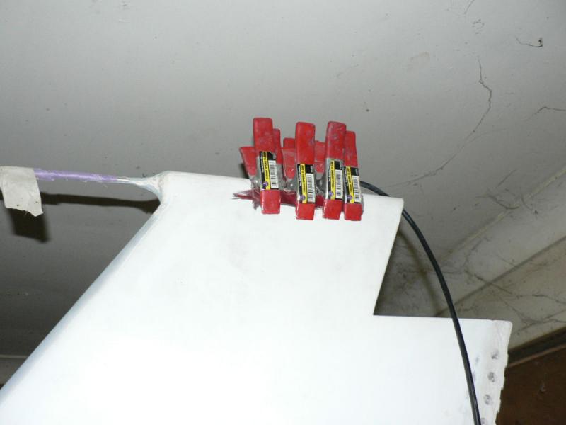
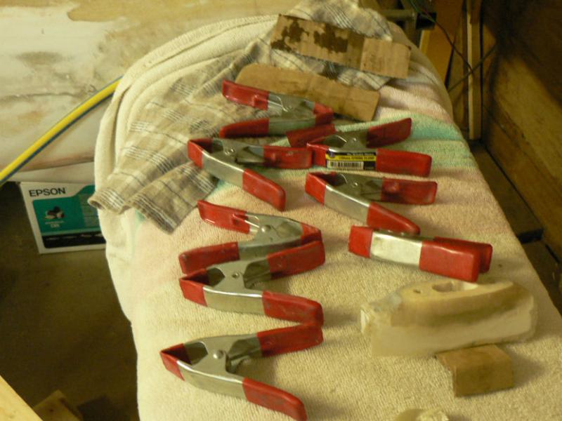
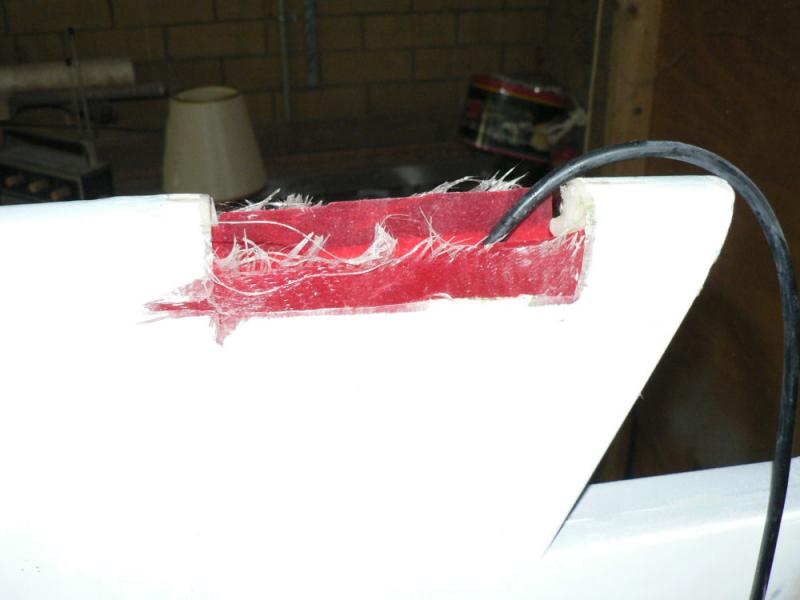
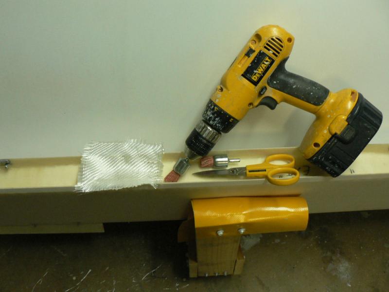
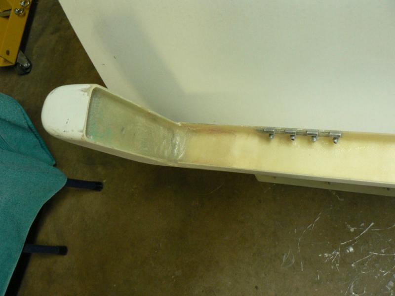
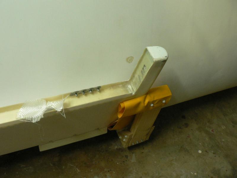
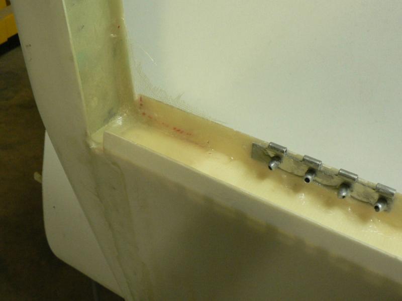
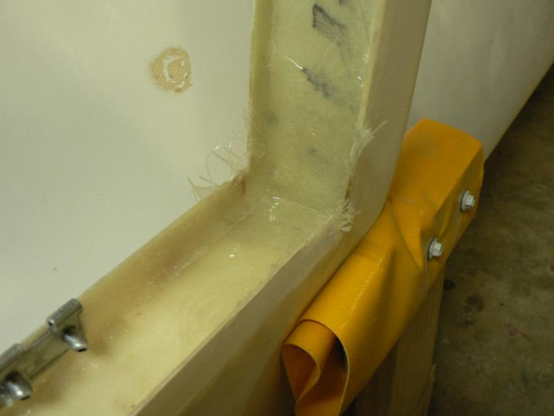
20081013 Remove strobe from fin top & disconnect original 3 core power line for strobe. File down joint area, abrade cloth join area inside - clean up with acetone Mix up epoxy, apply epoxy to inside join area Apply epoxied cloth to inside join area backed by peel cloth Back the peel clothed with stiff cardboard and use spring clamps to hold the cloth in place. Allow to cure then remove clamps, cardboard and peel cloth.
-

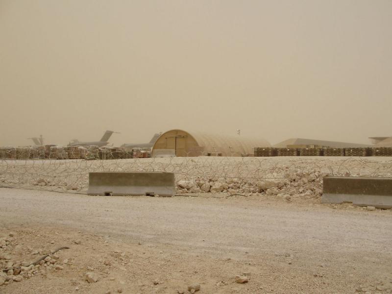
How is this for a dust storm thru Wagga today?
Ross replied to Captain's topic in Trips/Events/Seats
Bagdad weather A fairly common sight some weeks ago in Bagdad [ATTACH]6648.vB[/ATTACH]
-
20081004 We had some nice rain here last night 12.5 mm and a bit better in most of the snowy catchment. Fitting last layer of cloth reo to the elevator mass balance weight connection. Rub down the the proposed area for the reo cloth using a drill with abrasive tool fitted. Blow away dust with air. Clean up with acetone & rag. Mix epoxy Apply epoxy to elevator joint mass balance reo position. Apply cloth to epoxied area & press into place - apply more epoxy to surface to wet up fully. Makes it easier to prevent air bubbles than applying a fully wetted up cloth. [ATTACH]6642.vB[/ATTACH][ATTACH]6643.vB[/ATTACH][ATTACH]6644.vB[/ATTACH][ATTACH]6645.vB[/ATTACH][ATTACH]6646.vB[/ATTACH][ATTACH]6647.vB[/ATTACH] Wiped up any epoxy dribbles on flying surfaces with acetone soaked rag. Take epoxy sample & leave new reo to partially or fully cure before attempting to dress it up. Record Time, Temperature and Relative humidity until reo is cured.
-
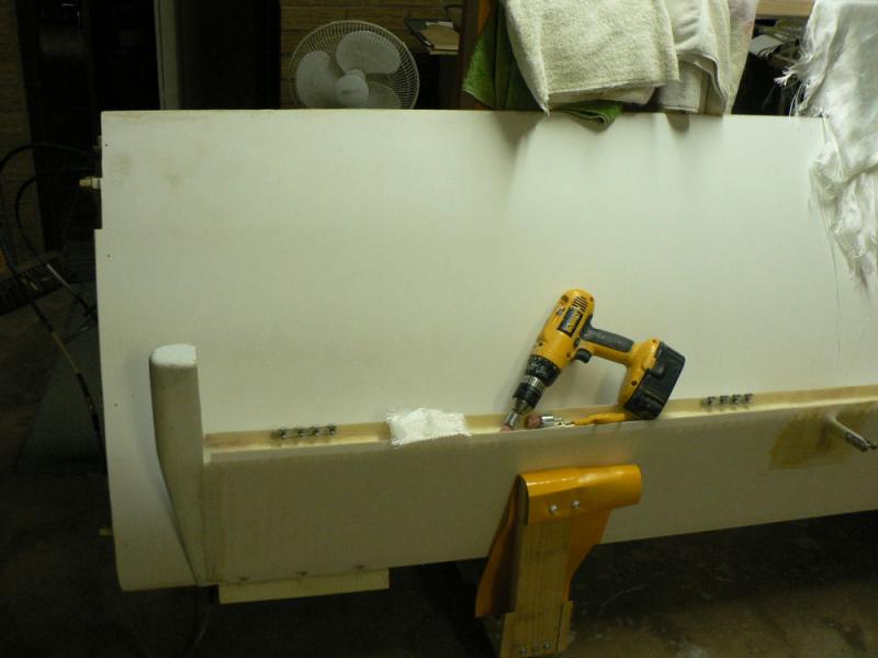
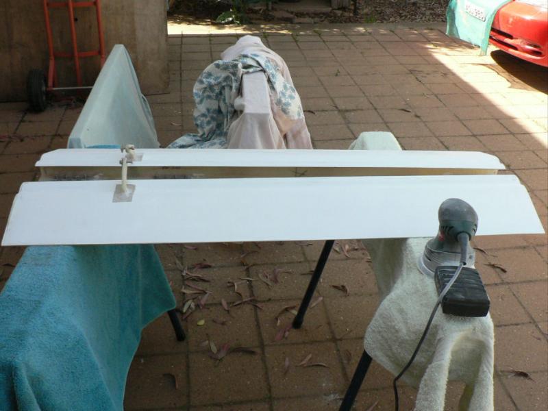
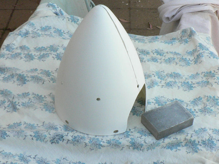
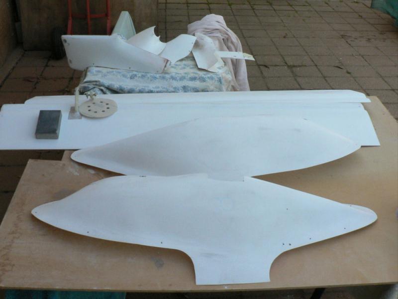
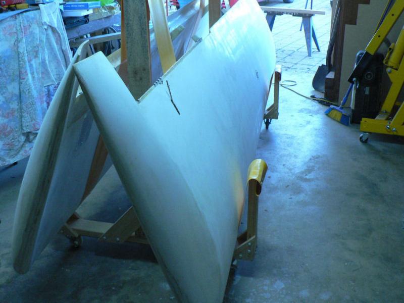
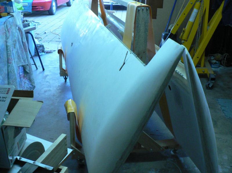
20081002 Using #400 grade orbital palm sander on ailerons, strut fairings, fuselage fairings, elevator and spinner. Then used wax and grease remover on the same parts except the elevator where I need to install some more cloth to secure the mass balance weights. Should have installed it all at once. [ATTACH]6634.vB[/ATTACH][ATTACH]6635.vB[/ATTACH][ATTACH]6636.vB[/ATTACH][ATTACH]6637.vB[/ATTACH][ATTACH]6638.vB[/ATTACH][ATTACH]6639.vB[/ATTACH] It was noticeable that the positions of the ribs in the elevator showed up after sanding. Although it does not show in the photo. This will probably result in some extra undercoat and weight being added there.
-
Hi Phil thanks for your info I had already conformed to most but not all of what you have recommended in your post. The other thing I had thought of when doing the original installation was to mount the dipole aerial inside the fuselage. There is enough room vertically at about the rib between #1 and #2 luggage compartments. I did not know what the radiation might do to the pilot or how much the pilot might affect the transmission and the reception. Plenty of GA planes have their non dipole type aerials mounted on top of the usually metal fuselage. I bought some 3 core shielded wire yesterday (the only one in stock locally) but one of the wires, the "earth" wire, is not well insulated from the shield and does not have it's own insulation. The owner thought he had some clamp type ferrite rings but could not find them having moved his stock into the new shop over the previous few days. So ordered some 4 core shielded wire from Jaycar pus some clamp type ferrite rings to suit the diameter of the wire. I still might have to do some radical surgery in the vertical stabiliser to get a new shielded lead for the strobe in there (or don't bother) or be more extravagant & install the twin model with a strobe on each wing.
-
Thanks Peter and Brian for your information and experience I rang Dan Mulder at Jabiru and he said to replace the original supplied high voltage unshielded wires from the strobe power supply to the strobe with shielded three core wire and only to earth one end of the shield onto the body of the strobe power supply. I had already tried good quality shielded wires (heavier) on the low voltage side of the power supply which probably doesn't do anything or make much sense now that I think a bit more about it. Temporarily putting the power supply in a metal cage did not make any difference either which possibly only leaves the high tension leads to the probe as being the problem. Dan said words to the effect that shielded wire on the high tension side should knock out the rising sound of the charge build up and most of the bang when it fires. So I went down to our local electronic shop which carries a fair range of stuff. I was looking for ferrite rings and shielded wire. However they are in the process of moving down the street to new premises and will not reopen until Wednesday. I am not sure that I will be able to replace the strobe high voltage wires due to the instructions and incomplete marking of holes in the fuselage that was on this particular early number kit #14.
-
I would not expect a totally frank reply to that question. I note that he said "no changes to the overall engine design were planned". There might be an "unplanned planning department". So it is still an internal combustion engine at least until the oil runs out! I think continuous change and improvements are continuously occurring as illustrated by the changes that I know of that have taken place over roughly the last five years. No doubt there are many more that I am not aware of. Original Jabiru motor change from 1600 cc to 2200 cc Oil pumps have had a number of changes of design. Oil coolers have had a number of changes. Seat belt anchors have been changed no longer attached to the UC leg mounting bolts. Door hinges have changed improving cabin sealing. Rain water leaks into top of door area has been changed Door closure security has changed. Carburettors have had at least two models of the same brand for the 2200 cc motor. Carburettors have had a number of changes of jets for the same engine Undercarriages legs have at least two variants for the J160 Undercarriage legs have changed for the J230 The propeller bolts and bellville washers and tensions have changed for the 2200 motor and probably the other motors as well The propeller flange bolts and tensions have changed tensions and sizes. Flywheel bolt sizes and tensions have changed for the 2200 motor Flywheel have changed from Aluminium to steel for the 2200 motor Flywheels now have dowels in them on all motors. Motors have gone from mechanical tappets to hydraulic tappets. The hydraulic tappet systems have been modified a number of times since their introduction in roughly the end of 2004. Time for major engine overhauls has gone from 1,000 to 2,000 hours. J160 cabins have been reinforced with additional fibreglass strips etc. UC axles and wheels have been changed on all models. A number of changes to the hydraulic disk brake system. Changes to fuel header tank type and location. A number of changes to the arrangement of the control stick. Changes to the ventilation controls. Changes to the cabin heater control unit. Sumps have been changed. Cylinder heads and barrels have been changed. Sloshing liquid for lining the fibreglass fuel tanks has changed.
-
Returned from USA via Los Angeles in 2000 on the last day of the Sydney Olympics in a Kangaroo 747 and about 140 miles East of Sydney the cloud tops were at about 55,000 AMSL if my memory is correct. I had wondered why we still seemed to be at normal cruise power and so high at the time until I saw the bright flashes in the solid clouds below us. It must have been an awesome sight from the flight deck. I think we were not very far from Sydney when they eventually reduced power for the descent into Kingsford Smith International to touch down at about 9:32 pm local time according to my watch. It is not that unusual to see fair weather cumulus cloud bases over 10,000 feet around Leeton in the middle of summer although the average bases are probably less than that. If you fly under fair weather cumulus clouds with good vertical development in summer here it is possible but not likely that you could experience rising air maybe as strong or stronger than 2,000 feet per minute up (approximately 20 knots up) but probably more likely in the range of 800 to 1200 feet per minute. I have had at least one flight in a glider where I saw the vario hard up against the stop which was at 2,000 feet per minute up. There is a real strong risk of being sucked up into the base of a cumulus cloud as you get nearer to it because the released latent heat from the moisture condensation can dramatically increase the strength of the thermal in and near the base of the cloud. As a very general rule if you fly under near the edges of cumulus clouds or in between them you will usually be flying in sinking air maybe as much as 2,000 feet per minute down! The sink rate will probably be less than the corresponding rising air that caused it. Of course there are often in the summer many hours of the day before the rising thermals get high enough to get cold enough to condense and form clouds. So it is handy to know the dew point temperature and the lapse rate and then you can work out the potential cloud base AMSL or even if there is going to be a cloud base. If you want to know more about this stuff ask a gliding instructor as I have forgotten more than I ever knew about it. In general if you fly through a big high pressure system you will be flying in a sinking air mass which does not do much for your fuel consumption or average ground speed particularly if you are on the wrong side of the high for the direction of your flight where in addition (or should I say subtraction) you would cop a head wind or X-wind instead of a tail wind.
-
Brian Thanks. I know of ferrite rings but not how to use them.
-
Biggles Thanks for that. I really did not think of the interference coming through the coax for the aerial although I did note that it seemed a fairly light coax. I actually used a heavy shielded pair for the power supply to the strobe power supply.
-
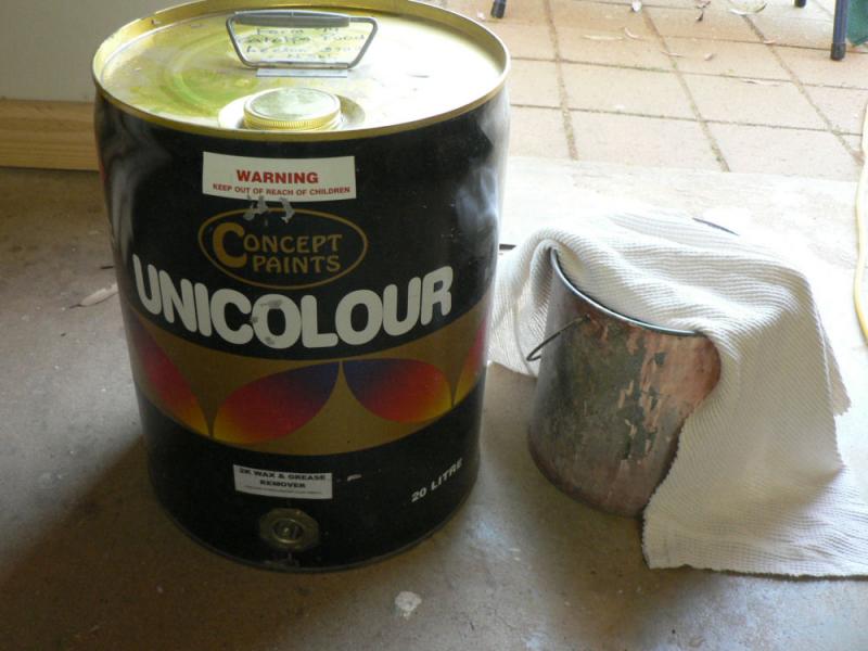
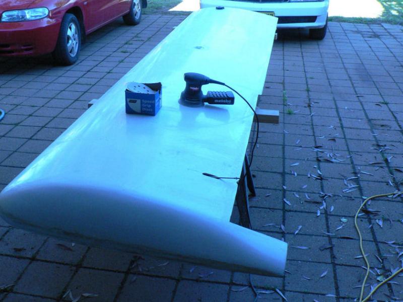
2008-09-27 Orbital sand both flaps after removing a few rough high spots with a scraper. Washed down both wings and both flaps with "2K Wax & Grease Remover" using a cotton rag & elbow grease. [ATTACH]6591.vB[/ATTACH][ATTACH]6592.vB[/ATTACH] Pic 2 shows a rough area on the starboard wing that should come up OK once it is undercoated with the filler and sanded down and probably undercoated again once or twice.
-
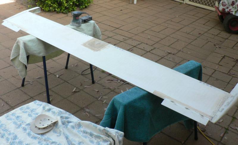
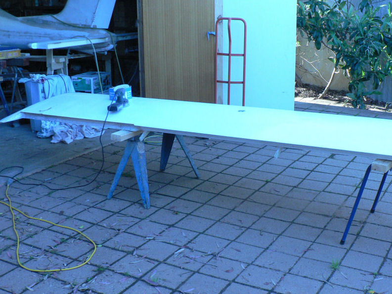
26-09-2008 Wings Orbital sand for painting A pair of trestles was set up outside the carport. Each wing was sat on the trestles and sanded with #400 grit sand paper using a random orbital sander. Each wing was done on both sides using two patterns - fore and aft across the wing and left to right along the length of the wing. The idea is to roughen the surface so that the undercoat will take to the existing surface. Also any high spots of epoxy or gel coat may/might be removed by sanding. Low spots will have to be filled with bogging undercoat or micro-ball epoxy. [ATTACH]6586.vB[/ATTACH][ATTACH]6587.vB[/ATTACH][ATTACH]6588.vB[/ATTACH][ATTACH]6589.vB[/ATTACH] Apologies for the wrong camera setting. Bad areas will show up better after the initial undercoat is applied and sanded going by experience on the part of the fuselage that has been started on with sanding and undercoat. This was the second attempt at posting as I had exited w/o doing the "Submit Reply" and had to start again.
-
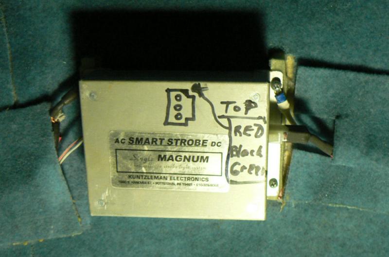
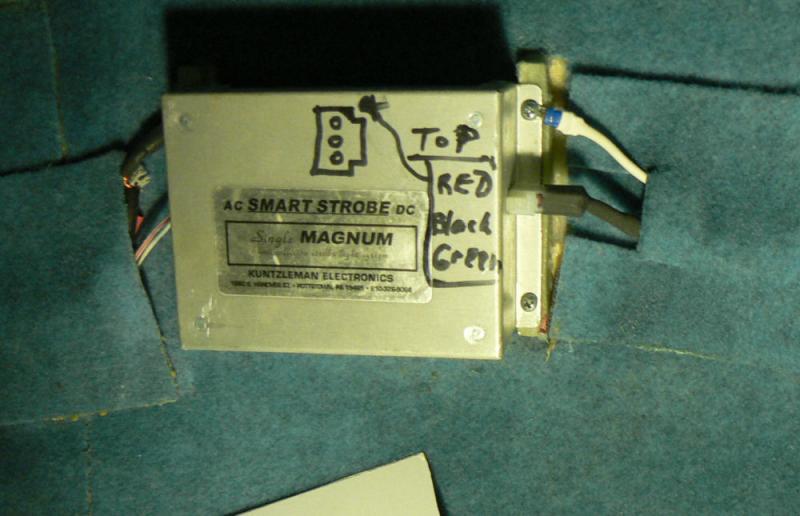
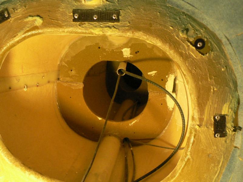
Hi BigPete That's the strobe power supply. According to the plans it was supposed to be on the floor in luggage 2 on the port side. But I had a fair bit of noise from it in the radio so I wanted to run the aerial wire away from most of the power wires behind the panel which are mainly on the starboard side. So the power wires for the strobe now come from the strobe power up the starboard side to behind the panel. The aerial wires come up the port side over the top and down the side of the windscreen and through the side of the panel into the radio which is centrally mounted in the panel. It did not make any difference to the noise although it can be tuned out with the squelch (a lot of squelch). It may not be a real problem as it might be insignificant when only tuned to local stations. At the moment while parked in the garage I have the radio scanning many stations like Griffith, Narrandera, Mount Gambier, Mildura, Dubbo and Melbourne Centre. This testing so far has been done without running the motor and without any transmissions on the radio as the plane is unregistered and not yet ready for flight. The prop has not been balanced yet and has not been checked for tracking either although it looked a fair way out when I tried mounting it. It has been removed again while I was checking the boss to crankshaft connection for the propeller. I note that the strobe power supply is now mounted on the engine side of the firewall for J230s which I presume might eliminate a lot of the noise from the strobe. It is fairly heavy so might have a significant effect on a J160 C of G position. I need to find out more detail from someone on how to suppress RF noise out of the strobe power supply from getting to the radio via the 12 volt wiring system. In fact does some or all of the noise actually come through the 12 volt wiring system which is shielded until it gets back behind the panel.