Ross
-
Posts
729 -
Joined
-
Last visited
Content Type
Profiles
Forums
Gallery
Downloads
Blogs
Events
Store
Aircraft
Resources
Tutorials
Articles
Classifieds
Movies
Books
Community Map
Quizzes
Videos Directory
Everything posted by Ross
-
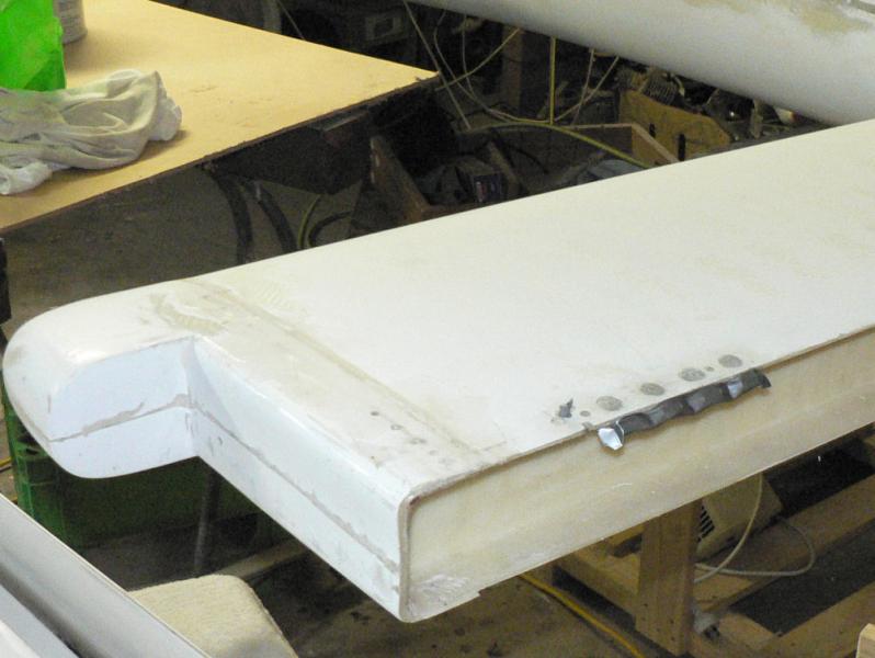
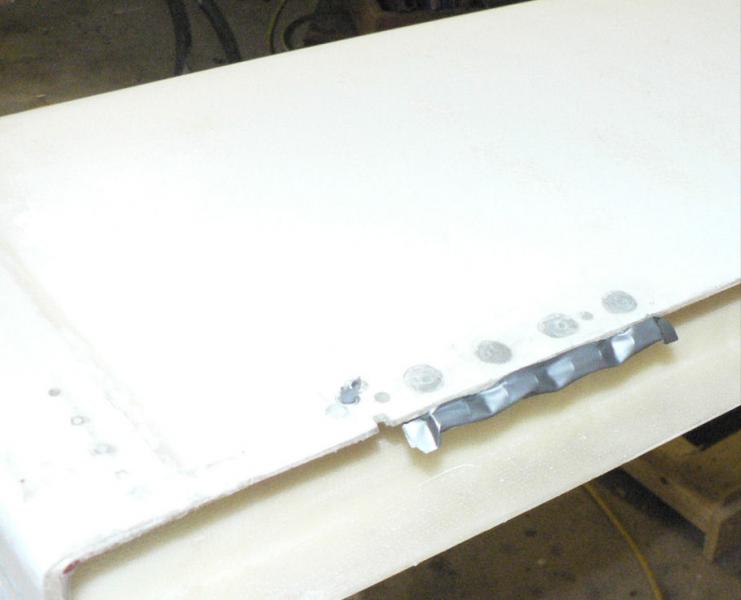
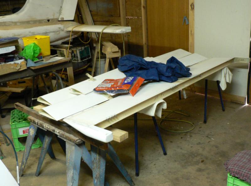
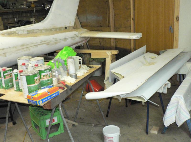
20090319 Prepare ailerons, flaps, rudder, horizontal stabiliser, vertical stabiliser for priming & undercoat. This may be extended to starting the port side of the a/c undercoat back to the firewall from the tail group. The starboard side is well down the track of undercoating and filling rough areas but needs more work around the horizontal stabiliser and around the cabin area up to the firewall. Undercoat/filler paint, top coat paint, their respective activators and thinners, spray gun, air gun, trestles, measuring jug (need to make up a dip stick) and electric drill to power paint stirrer, rags, spare acetone for cleaning, air gun, screwdriver, small hammer, protective clothing, latex gloves, mask, filters and air compressor were assembled. The gel coats of the control surfaces have all been rubbed down ready for priming and undercoat and cleaned with acetone and with compressed air. There is no sign of pin holes in the gel coat on these surfaces but the underlying fibreglass is exposed around the lever position on the elevator which will require extra attention (coats of filler & rubbing down). The hinges were all covered with tape to keep paint out of the hinge holes. [ATTACH]7398.vB[/ATTACH][ATTACH]7399.vB[/ATTACH][ATTACH]7396.vB[/ATTACH][ATTACH]7397.vB[/ATTACH] All the captive nuts for the hinge pin safety lugs were filled with tape to prevent entry of paint. Possibly prime and undercoat the control surfaces tomorrow outside the car port providing it does not get too hot or windy.

-
20090212 Get wings ready for sloshing. Removed breather pipes & earth wires from both wings. Removed finger strainers from both wings. Removed quick drains from both wings. Fitted all tapped holes with brass plugs ready for sloshing tanks over the top of the original sealer. Need five plugs per wing. [ATTACH]7394.vB[/ATTACH][ATTACH]7395.vB[/ATTACH] The completion of this was delayed by family commitments and availability of help.
-
If you are on cable, the cable usually might serve a whole street with its limited capacity. So normally the more users that are active the less capacity each one has access to thus causing delays in cable traffic. Trying the connection at times when there is less likely to be heavy traffic might give better service indicating the capacity of the cable is unsatisfactory at normal times.
-
A towbar attached to the front U/C wheel axle (bolt) sounds like a very sensible aid that might reduce the tendency by most willing helpers to pull an aeroplane around by pulling on its propeller. The Jabirus with their wooden propellers must surely be easily disturbed by uneven pulling or pushing on their props.
-
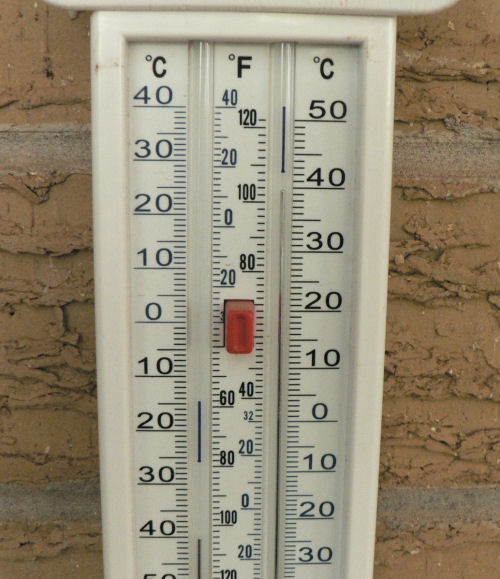
Back on topic of temperature to stop flying of 40 degrees C at MTOW as quoted for the Jabiru J160 and the Jab LSA-55 in their respective POHs. A possible extra consideration besides the A/C structure might be the upper limit for engine oil temperature. If the ambient temp is high enough the engine cooling system may not be able to keep the oil temp low enough to keep oil oxidation down to a practical level thus producing rapid engine failure.
-
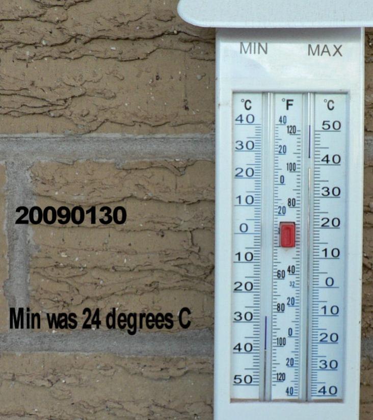
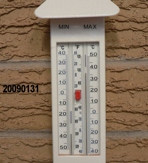
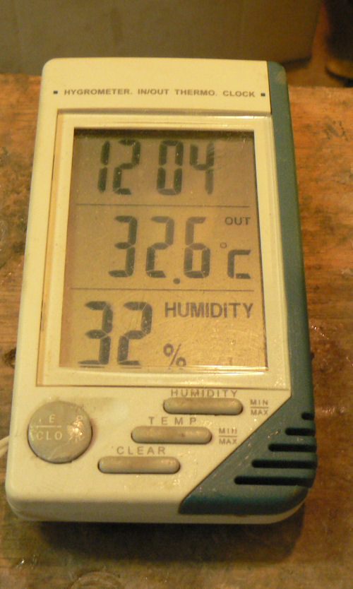
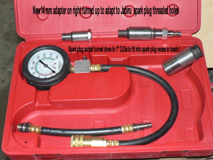
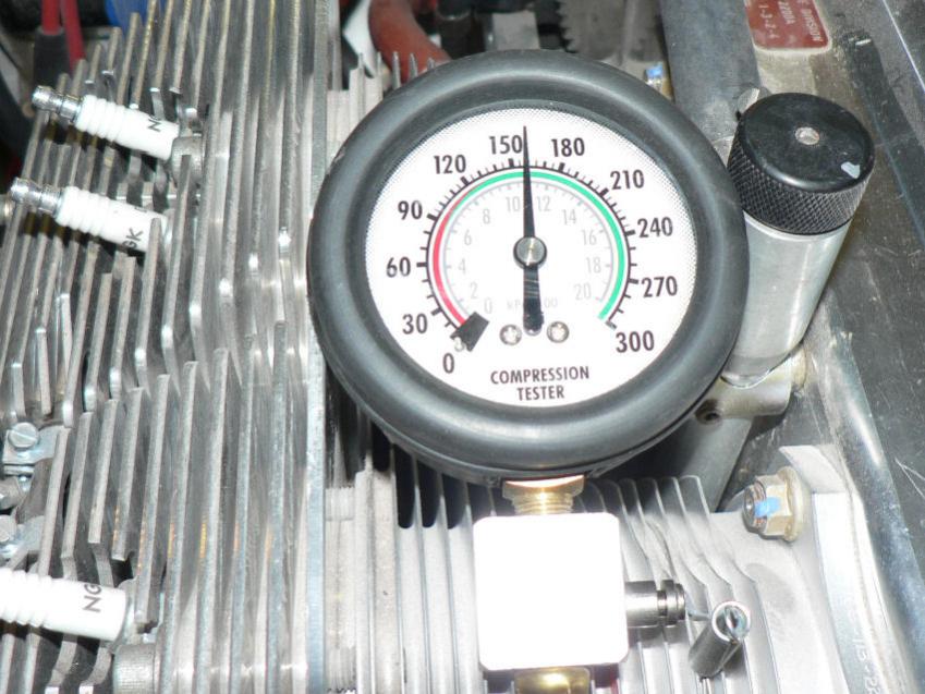
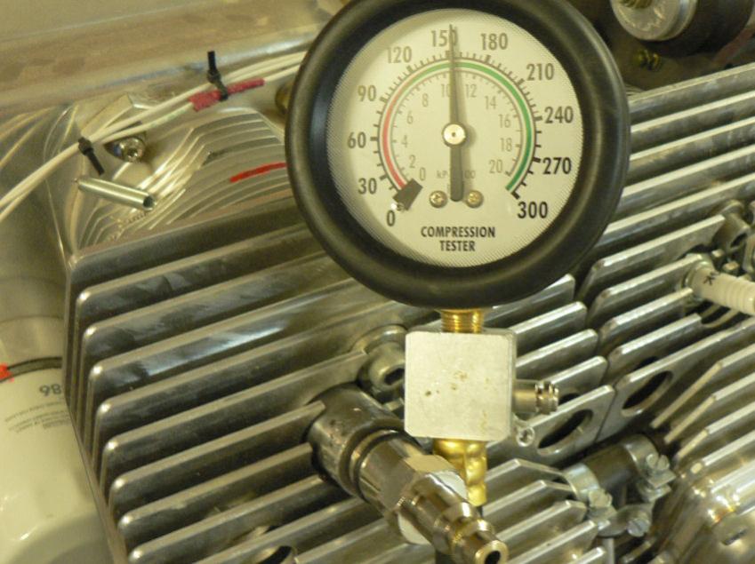
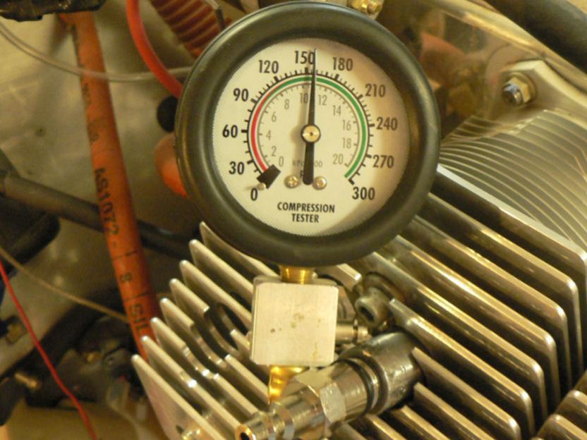
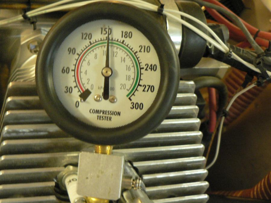
20090131 The warm weather continued here, but not as warm as some others were experiencing. The air conditioner works well but is not in the garage. Last night at about 7:30 pm we had a bit of a southerly gale with thunder and lightening with heavy rain for about five minutes - it sounded like hail - all of two mm or 8 points. Immediately following that, the wind turned 180 degrees to give us a very hot northerly almost a gale until well after midnight. [ATTACH]7132.vB[/ATTACH][ATTACH]7133.vB[/ATTACH][ATTACH]7134.vB[/ATTACH][ATTACH]7135.vB[/ATTACH] Now having all the bits at last, decided to do a compression test on the motor. The new adapter to fit the Jab spark plug holes/threads was a bit short raising the chances of damaging the head cooling fins when tightening and removing the adapter. So might get another one made eventually a couple of inches longer. The bore of the adapter needs to be small so that it does not reduce the pressure excessively. I just noticed that I entered the wrong size of the plug thread on the lid of the compression test box. The 14 mm should be 12 mm (actually measured 11.83 mm on a spark plug). [ATTACH]7136.vB[/ATTACH][ATTACH]7137.vB[/ATTACH][ATTACH]7138.vB[/ATTACH][ATTACH]7139.vB[/ATTACH][ATTACH]7140.vB[/ATTACH][ATTACH]7141.vB[/ATTACH] The pics of the compression tests are shown here in the order of cylinders 1,2,3,4. The Jab engine book says to do the compression test with the engine oil temp between 30 degrees C and 80 degrees C. That was not a problem even at 10 pm in our garage on the night of 20090130. However due to a number of the pics being blurred due to not using the flash to prevent glare I did them again the following day arranging the garage lighting a bit better. When it came time to enter the results on the forum it was in maintenance mode. So they are going in this Monday morning.
-
20090125 It has been a bit warm here lately plus a few other excuses. [ATTACH]7093.vB[/ATTACH][ATTACH]7094.vB[/ATTACH] A few weeks ago decided to buy some spare spark plugs for the 2,200 motor. There were none in stock or ever had been in Leeton that I could discover. So ordered a packet of ten which came the next day for $45 for ten plugs. Eventually opened a spark plug box to discover that that particular 12 mm plug comes without the nuts on top of the plug - the only plug in the whole range for that brand without the nut. This missing nut had been mentioned in someone else's post earlier on but I had forgotten. After visiting a number of garages, I eventually found one that was willing to give me the nuts off ten as new plugs probably 20 years old hiding in a back store room. It turned out that all the nuts from all the old plugs fitted the new plugs! I could hardly believe it. I also thought that I should check out the compression tester that I had bought a year or two ago only to discover that it did not have a 12 mm adapter to fit the Jab spark plug holes in the heads. Eventually found a shop where I could get an adapter made to suit the Jab engine 12 mm holes but the turner who operates the lathe involved was on leave until this coming week. So with a bit of luck might have it by the end of this coming week.
-
Hi Allan for interest's sake The Jabiru J160 kit Owners manual that I possess for kit#14 does have a reference to an 85 Kg person sitting with the seat fully forward and a 95 Kg person sitting with the seat fully back (in relation to the "Aircraft load and Trim Chart") on Page 6-8 of the J160 owners manual. A number of other conditions are stated in the example. These two weights and positions are quoted as an example, NOT as a recommendation in reference to forward and aft limits of the C of G. A number of other conditions are stated in the example. Any pilot and or passenger loading must be quoted in conjunction with the "Aircraft Load and Trim Chart" which is too complicated to explain without reference to the example "Aircraft Load and Trim Chart" and the clean unused "Aircraft Load and Trim Chart". However this a/c does not have adjustable seats although the effect can be achieved by placing cushions behind the passenger and pilot's backs as required. It has an "Occupant weight versus Crew index units" chart implying (but NOT stating) a maximum individual crew weight of 120 Kg. The ladder scale for total crew weight on the main part of the "Aircraft load and Trim Chart" goes up in steps of 10 Kg to 300 Kg (but does not say whether the limit is higher or lower than that) which at 300 Kg would not leave much capacity for fuel and other odds and ends. Nothing is said about the structural load carrying capacity of any individual seat. It is all about weight and balance with full tanks and empty tanks.
-
Hi Bob Yes I had the same problem with the same measurements quite some time ago and like you I had rung Jabiru and their response was not so helpful then at all. So I was pleased to see the new instructions in the current J160 construction manual. The original measurements meant that the rudder cable anchor had to be located exactly in the right place. When it was there, there would be practically no allowable adjustment leeway left at the rudder end of the cable. I had originally mounted my cable anchor on the fuselage where the positions were marked by the factory only to find they would not work because of the angles and the position was out for cable length. After moving it again I eventually decided to put the cable in the top of fuselage strut but had to drill a hole out of it into the fuselage etc to get back to the control stick. I still had to experiment to get a mid adjustment location for the cable anchor on the rudder end. It is a bit worrying that the J170 essentially the same A/C as the J160 except for the longer wings has gone back to that originally specified dimension for the earliest J160 of the allowed rudder movement. So will we have a lower cross wind tolerance allowance for the J160 compared to the J170. Will there be any effect on the J160's susceptibility to spin or the J160's ability to recover from a spin or a spiral dive. Regards
-
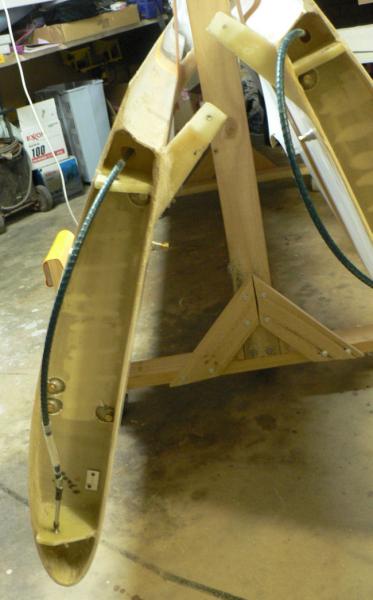
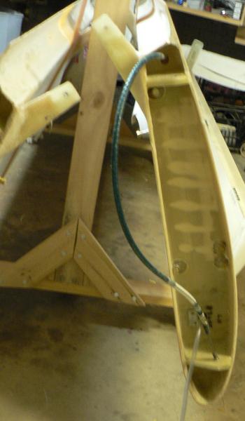
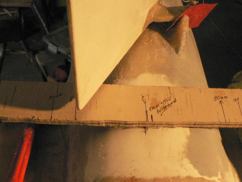
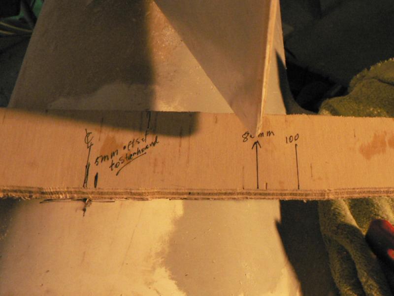
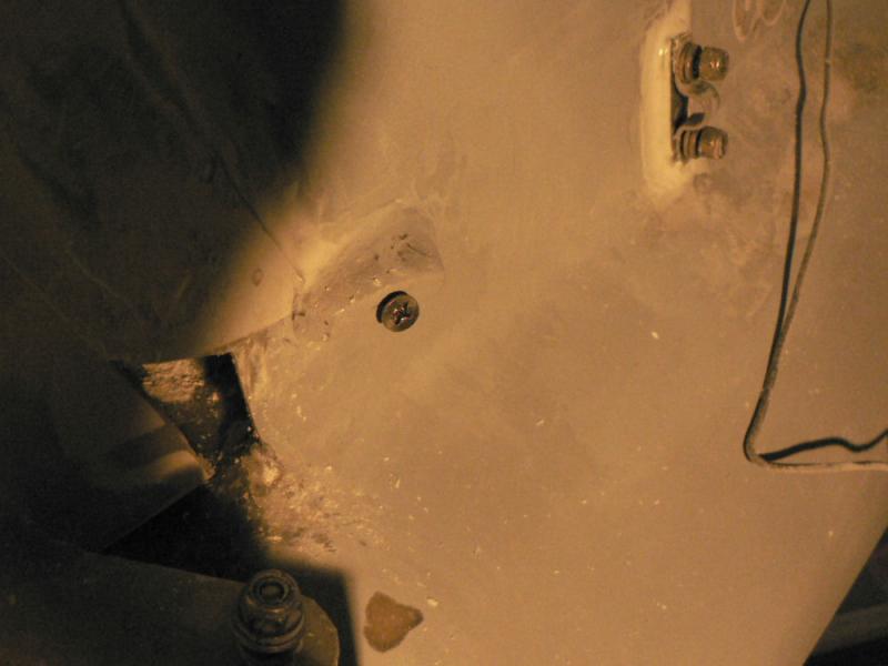
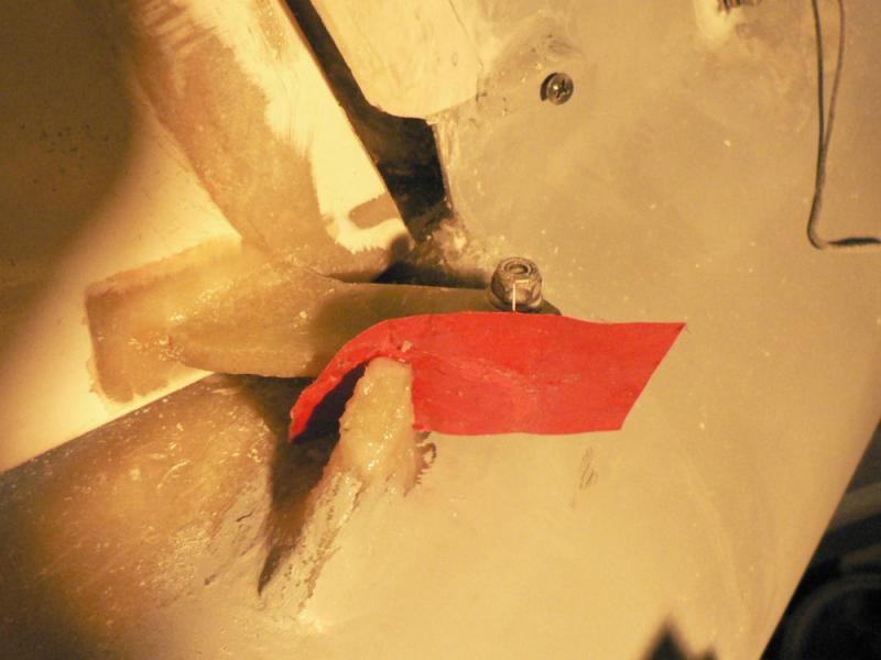
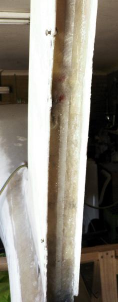
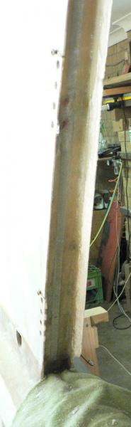
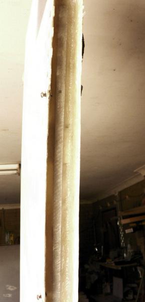
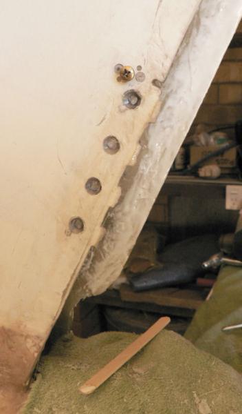
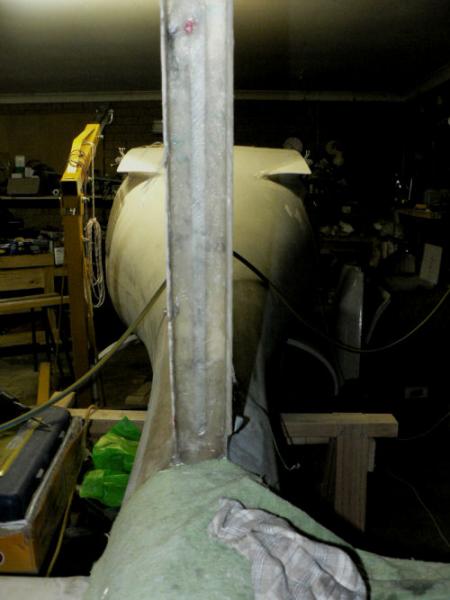
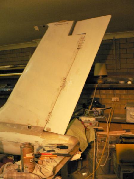
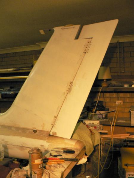
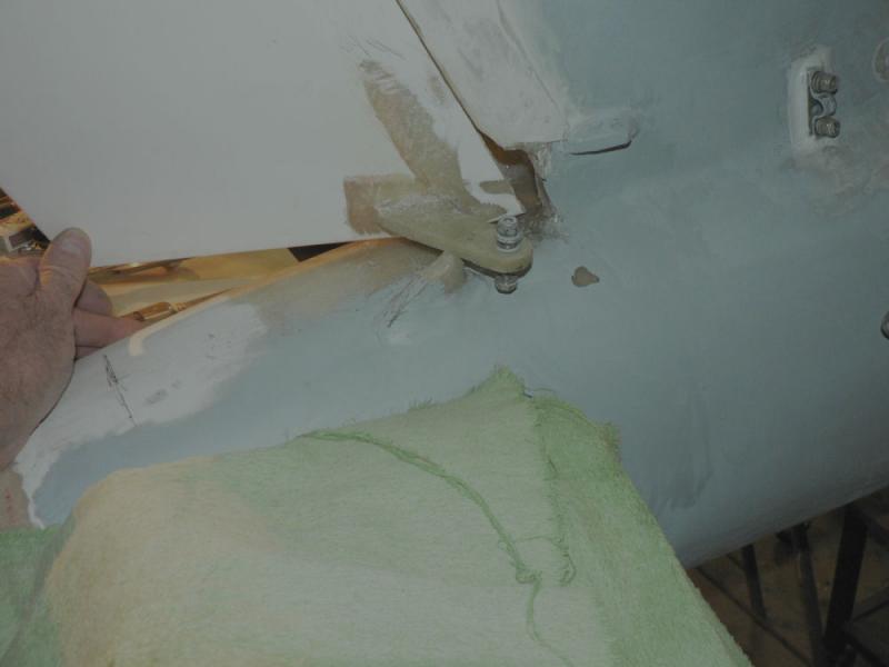
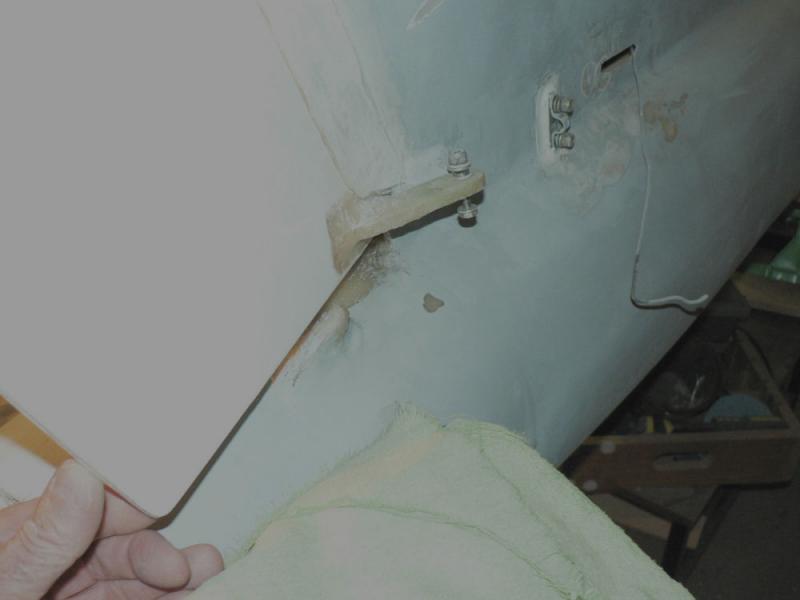
20090110 Drilled out three of the rudder hinge CSK rivets in the vertical stabiliser as they were proud of the stabiliser - not enough countersinking. Used the countersinking tool which I had bought after doing the original rivets on the stabiliser. Mixed up some epoxy and flock which was applied in the countersink holes before inserting the rivets and pulling them. 20090112 Checking out the rudder stops. Started by reading the section from the new J160 construction manual. Basically it says to find the centre position of the rudder by clamping some mixing sticks on the port side of the top of the rudder and let them align with the vertical stabiliser and the mass balance on the top of the rudder. But my mass balance is slightly wider than the vertical stabiliser so I applied sticks on both sides and think that I have found a centreline. Once the centreline was found and marked on the top of the tail end of the fuselage and on a plywood template an offset was marked 5 mm to the starboard side of the A/c on the template. Using the offset as the zero position two lines were then marked - one 80 mm to port and one 80 mm to starboard from the offset mark. (This is a much easier and far less ambiguous method than was published in the original manual.) The stops were both allowing more deflection for each side as originally done by me which made it much more difficult to set the anchor point for the rudder cable. I see that the J170 has a deflection of 100 mm each side of the offset line?? I note that there are other small differences in the area of the rudder hinges. So the starboard stop was made adjustable by inserting A SS self tapper into the existing stop and leaving it proud of the stop. The port stop was a bit low and had a gap when the rudder was in the correct position. So the port stop was packed up with two small pieces of fibreglass and then flocked in place. The preparation was to file the parts to fit and the site, clean it all up with acetone, prime the parts and the site with epoxy. The remaining epoxy was mixed up with some flock and applied to the parts with the rudder set in the correct deflection for the port rudder stop. Some peel cloth was applied to prevent the new work adhering to the rudder arm. [ATTACH]7059.vB[/ATTACH][ATTACH]7060.vB[/ATTACH][ATTACH]7061.vB[/ATTACH][ATTACH]7062.vB[/ATTACH] Then it was allowed to cure.
-
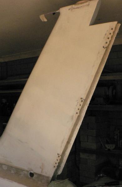
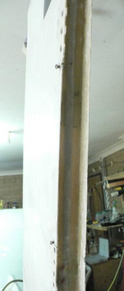
20090109 Prepared top half of U channel in vertical stabiliser for fitting a layer of fibreglass after removing the previously fitted layer. The main tool used was a 6 mm wide wood chisel. Used an abrasive cloth wheel in a drill chuck to to roughen up surface for application of epoxy. Blow out dust Clean liberally with acetone. Mix up batch of epoxy resin - and apply to surface to prime it. Mix up batch of flock and fill each side of aerial to make a smoother contact for the fibreglass cloth. Apply a layer of epoxy resin to the whole area to be covered in fibreglass. Apply a layer of fibreglass over the aerial and the LHS of the U shaped channel. Press in the fibreglass layer with fingers to wet it up completely and making sure to remove air pockets. Apply epoxy resin to the top of the fresh fibreglass. Apply the RHS fibreglass in the channel overlapping the fibreglass just laid. Press in this layer to wet it up and to ensure no air remains under the layer. Apply epoxy resin to the top of this fresh fibreglass. Mix up a batch of micro-ball epoxy resin and apply it to the trailing edge of the U channel on the RHS. [ATTACH]7026.vB[/ATTACH] Pic 1 [ATTACH]7027.vB[/ATTACH] Pic 2 [ATTACH]7028.vB[/ATTACH] Pic 3 [ATTACH]7029.vB[/ATTACH] Pic 4 [ATTACH]7030.vB[/ATTACH] Pic 5 [ATTACH]7031.vB[/ATTACH] Pic 6 Allow to cure - monitoring the micro-ball layer as it will droop & run so requires some manipulation as it slowly firms up as it cures.
-
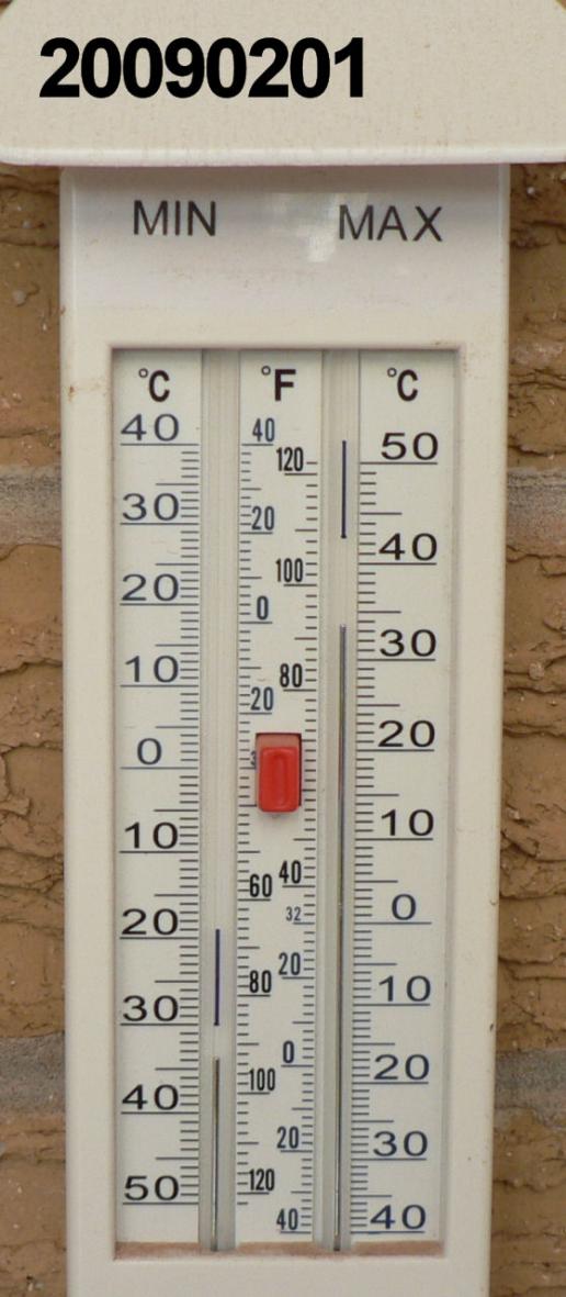
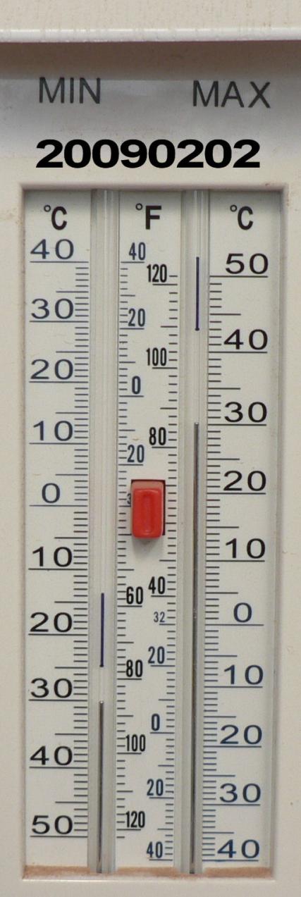
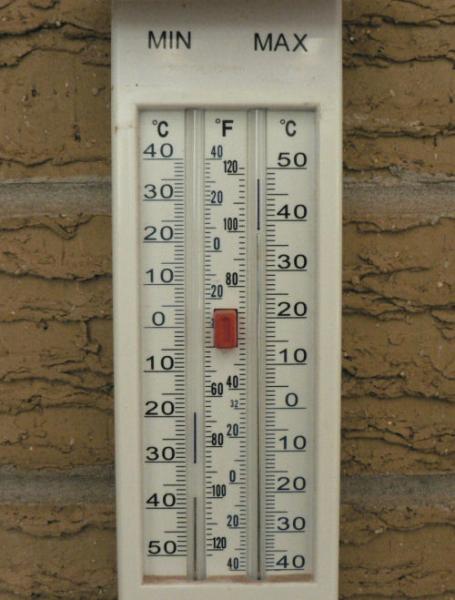
20090106 Removed the remains of the rudder hinge rivets from the vertical stabiliser. There were too many air pockets mainly against the aerial in the channel of the vertical stabiliser trapped under the new layer of fibreglass. So stripped out the middle of the fibre glass in contact with the aerial. The right angle space between the aerial and the layer underneath it was filled with flock on both sides of the aerial for the bottom half of the vertical stabiliser. The left hand side of this space was then covered with a layer of fibreglass which was pressed into the flock and a layer of freshly applied epoxy. The right hand side of this space was then epoxied and a layer of fibreglass applied overlapping the previously applied layer. Then both layers were brushed with a layer of epoxy. [ATTACH]7013.vB[/ATTACH][ATTACH]7014.vB[/ATTACH] As the temp outside in the shade was 40 degrees C decided to leave the rest. At 17:30 hrs it was still 35 degrees C inside the carport. The fibreglass is substantially cured.
-
20090105 Pulled off the clamps, the wood strips over the hinge positions and the peel cloth. The epoxy has not fully cured yet - but still curing - temperature still a bit over 33 degrees C in my carport at 9:30 pm. Cleaned out the hinge rivet holes in the vertical stabiliser. Remounted the rudder hinges loosely on the vertical stabiliser using 2 only AN3-4A bolts, nuts and washers on each hinge just to make sure it still lines up approximately and the rudder still has full deflection to the stops or close to it. Refitted the rudder with the rudder hinge pins. Made sure the rudder has full movement, clearance and no gap on full deflection to the left. [ATTACH]6996.vB[/ATTACH][ATTACH]6997.vB[/ATTACH][ATTACH]6998.vB[/ATTACH][ATTACH]6999.vB[/ATTACH] It should only need some minor filing and perhaps some hot air heating to get a good free rudder connection once the countersunk 3/16" hinge rivets are replaced,
-
On the question of fuel pump working or not. You might be able to monitor your fuel pressure and hence the condition of your fuel pumps depending on where you mounted the take-off for the fuel pressure. As the pressure is likely to be oscillating depending on what types of pumps you have it would necessitate having a restriction in the pressure line and possibly an air reservoir to smooth out the varying pressures unless you wanted to go digital and display the pressures on an oscilloscope type screen. I am guessing that the pressure each pump could produce are likely to be quite low - again I guess something like 3 to 8 psi. Also a pressure sensor or sensor line line is another possible place for the fuel system to have a fault. An air leak or a fuel leak. Pressures produced by in line pumps (like the electric pump + the mechanical pump) are cumulative so a measurement point just before the carburettor can pick up total pressures from both pumps. Also running both pumps could raise fuel levels in the carburettor compared to one pump at a time possibly making the engine run richer than with one pump. This condition is not likely to be objected to on take off and initial climb or on final for landing but it might not be desirable for cruising. The construction manual (early J160 manual) locates the electric fuel pump a little above the header tank and between it and the mechanical fuel pump on the engine. It would be more desirable to have that electric pump in the lowest point in the system especially if using fuels with vapour pressures higher than normal. Someone that knows something about the subject might like to comment. Regards
-
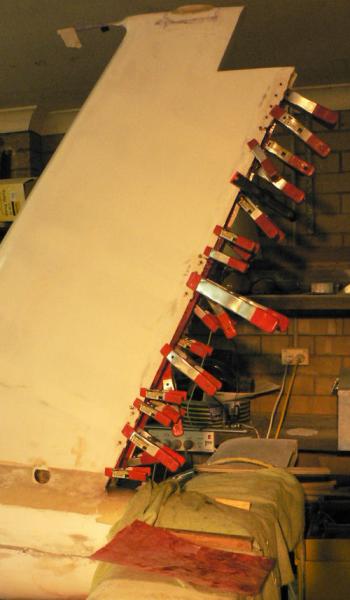
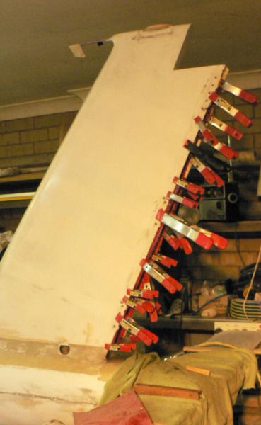
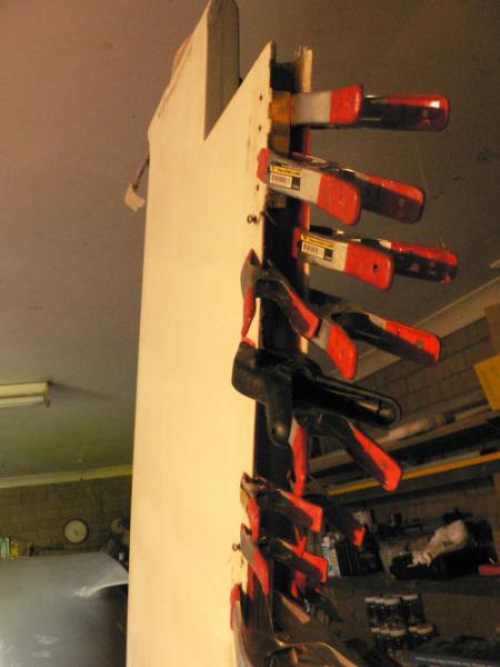
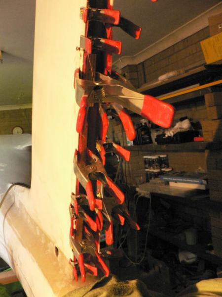
20090105 Mix up epoxy for vertical stabiliser rudder rudder channel for adding the last fibreglass layer. Prepare vert stabiliser rudder hinge area position for epoxy and fibreglass layer. Pre-cut out a fibreglass layer to match the channel location on top of the radio aerial. Scrape and abrade area with sand blaster, knife and abrasive cloth wheel mounted in a drill chuck. Blow air on area to remove dust off the area. Clean area with acetone and a rag Prime area with a layer of epoxy applied by brush Apply fibreglass layer Use small clamps to hold glass after it is pushed in place from the top down trying to keep air out from under the glass. Apply more epoxy by brush to wet up the whole glass layer Use clamps, wooden strips over the hinge positions and peel cloth to hold down the fibreglass in place. [ATTACH]6992.vB[/ATTACH][ATTACH]6993.vB[/ATTACH][ATTACH]6994.vB[/ATTACH][ATTACH]6995.vB[/ATTACH] Keep wiping up dripping epoxy periodically from the job. Allow to cure
-
20081230 We are now back from near the coast for most of last week where we saw lots of large screaming things overhead Concord mostly heading west and south-west. We do not see them as close up in Leeton but we can usually tell where they are going or coming from. Sydney traffic for Perth, Adelaide and Melbourne can usually be seen from here as well as Melbourne traffic for Brisbane or Coolangatta. At times we also see North South traffic very high and a bit west of here. An order for some CSK rivets from Jabiru arrived while we were away sent on 19th Dec by Jamie just before they closed up shop for Christmas. A spruce parcel arrived this morning from USA as well. A sandblasting gun from the Supercheap Auto Store in Griffith was purchased this morning as well. Saw a very dark plane similar to a Foxbat fly past last evening at 19:45. He had his front light (landing light??) on and it could only be seen in silhouette against the sky above. He appeared to be in a hurry.
-
Hi BigPete Thanks for that I shall check it out as we have a car club here. Regards
-
Being the owner of a fibreglass aeroplane kit makes the aircraft ground a fairly difficult concept for me especially as mention is usually only made of the metal aeroplane situation. For a fibreglass a/c there is no such thing as an earth return based on the aeroplane structure so I would have thought that this would eliminate some problems and generate some others. Regards
-
Just a note re the tyre & puncture problems. Some people around here have used various goos in their tubes to prevent loss of air with punctures. This usually resulted in violent shaking after lift off resulting in one case of a cracked windscreen. Applying the brakes immediately after lift off will help for the mains but not for the nose wheel on the Jabiru. A local L2 commented that once these goos had been inserted resulting in a good coating inside the tube then the tube should be removed and squeezed and worked to remove any mobile goo through the valve teat. The mobile goo would have been contributing to the out of balance condition. In my case (yet to fly it) I wanted to avoid the movement of goo in the tube by either using heavy duty tyres or inserting liners into the tyre to protect the tube. Any of these actions would probably contribute to putting the tyres out of balance, a scary experience, so I am interested in getting the tyres balanced. I would think that they could be readily dynamically balanced by spinning them on the A/C at high speed and balancing them to compensate. My local tyre shop says that he cannot dynamically balance the wheels when removed from the A/C because his fittings will not match the Jabiru wheels. I have managed to roughly statically balance them which would be a start but I would rather have a dynamic balance.
-
Continued near new year - before or after........!
-
Hi Geoff I presume there would still be plenty of heat from all over the engine in particular the sump, the oil cooler air, the ducted air off the piston heads and barrels and the exhaust header pipes before they get to the muffler and the inlet air itself. All that air is in the engine bay and is heated by the engine one way or another except the air going into the carburettor. That air has to go past the carburettor before it can escape from the engine bay. Anyway I am not committed to insulating the muffler or anything else. I just want to be able to do it immediately or take it off if it is required. I am aware that you are very conscious of keeping the engine heat down by keeping up a good airspeed as you told and showed me at Leeton as the POH also indicates. So I have kept that good advice in my head and seen it proven a few times since that flight in a few dead engines. Regards
-
Hi Grant If I come back in another life and buy a kit aeroplane I will not buy anything for it including the engine until it is finished. Hi Grant I have discovered that there are now strobes available for use in "experimental" aeroplanes using Extra bright LEDs at a few more $ than standard strobes which require about a 400 or 500 volt pulse to generate the flash power thus creating a radio signal. The LED type do not create RF interference according to the manufacturers. See the following site for their specifications on their range of LED fitted landing lights, spot lights and LED type strobes. http://www.aeroleds.com/media/pdfs/grid_comparison.pdf As you can expect they are made in the USA and are dearer than the standard ones that Jabiru supply which are also from the USA. I got my ferrite clamps and 4 core shielded wire online from Jaycar electronics. Regards
-
20081215 Removed the rudder hinges from the vertical stabiliser to put another layer of fibreglass inside the rear of the stabiliser. I drilled out the rivets and pulled their remains out/off with a pair of pliers. The tapered top of the rivets has been left in place for the moment. The aluminium hinges were heated from the inside of the channel with the hot air gun until they were fairly hot to the touch but not enough to cook the fibreglass. They were then easily pulled off with the pliars without distorting them. They were marked T, M and B for top middle and bottom. I did not do this originally because of the problems of clearance for the rudder as I had to put in a fibreglass strip under the hinges as the rudder had to be moved aft to clear the dipole aerial when full right rudder was selected which also caused a gap when full left rudder was selected. That gap has since been rectified some time ago by adding a thin strip down the starboard side of the trailing edge of the vertical stabiliser. The inserted strip under the hinges had also reduced the clearance between the rudder and the inside edge of the stabiliser on the starboard side. Putting the dipole aerial in a corner of the vertical stabiliser channel instead of the middle of it before any glassing had been done might have solved both problems without the need to move the rudder aft or put a strip down the starboard side of the vertical stabiliser. Also I think I have figured out how to hold a new piece of wet glass in place against the law of gravity. Jabiru were at work today/yesterday and Jamie said he would send some more Tapered aluminium rivets when I rang or the next day.
-
There are a number of reasons that made me decide on the Gamin 296. A few of them are that:- I like the USB computer interface that it comes with. It runs on mains a/c power if available and continues charging its own internal battery at the same time if it needs too. If the option is set, it can switch to internal battery power automatically when/if the external power fails or switch off the GPS with a timed warning on the screen. The external power will last over two hours. It has terrain awareness that can be set to whatever margin you want. The USB interface is easy to use and much faster than using a RS-236 serial interface which is what my many years old hand held Magellan GPS 320 uses to talk to my computer at 1200 baud. Adding extra memory is expensive though (or was when I bought the Garmin GPSmap 296) at about $500 I think for 500 MByte of RAM. Some other models or brands use industry standard memory cards. I saw a 16 GByte card at Office works in Wagga a couple of weeks ago for around $100 (my memory of the price may be wrong). The other problem was that the non registered non Jeppersen Australian airfields that were loaded on it when I bought it were all deleted either by the process of upgrading the GPS operating system software to the latest version or by the loading of an upgraded Jeppersen data base. Regards
-
Hi Jack I don't think I could turn my brackets around with the supplied bottom cowl. I actually had to remove some fibreglass off the back of the air cooler intake as it was touching the oil cooler in the present configuration. This cowl is substantially different from the original and has much more bottom lip than the original to help the air flow presumably. If you could do a pic or two it might be helpful at least to see what I am missing. If I picture it in my mind correctly you also probably get more airflow over the bottom of the sump as it leaves the oil cooler. Regards