Ross
-
Posts
729 -
Joined
-
Last visited
Content Type
Profiles
Forums
Gallery
Downloads
Blogs
Events
Store
Aircraft
Resources
Tutorials
Articles
Classifieds
Movies
Books
Community Map
Quizzes
Videos Directory
Everything posted by Ross
-
Hi ROM For JL I was not really up to the Nimbus or Janus either only having one flight in each but I can still vividly remember the flights as being absolutely magical compared to what I was used to flying at the time. The only trouble is that the vivid memory of two flights is becoming like the "not so vivid" memory of one flight being unable to distinguish between the check flight in the two seater and the flight in the Nimbus. The scale of the operation here at LEETON nowadays is nothing like that at Horsham at this stage of the game but I am envious of the situation you are mostly enjoying there. After letting my GFA ticket lapse, I did my RAAus conversion at Griffith with the Griffith Aero Club which had just started to cross hire a Jab LSA at the time. Griffith Aero Club was basically a GA club owning a number of GA planes with a number of others available for hire. As my GFA tickets had lapsed I did not get credit for the 8 hours and 192 hours flying experience that I had respectively in GA and gliders I had driven over there 60 km to start and waited around for most of the day to get a flight and after signing away the first $2,000 if I stacked the plane, joined the club paying all the RAAus stuff at the time and was eventually asked if I wanted a TIF. I said NO. Start the instructional flights now, today! So I got my first flight in a Jab with the instructor eventually telling me quite a few months later not to keep landing on the numbers! I must have been missing them most of the time up 'till then! I was surprised to find out later that I was the first student in that factory built Jab which had about five hours on the clock when I started. I think that I might also have been the first RAAus (ctually AUF) student of that instructor, Ben Jones, at the time. Ben has since been hired by REX and joined their training program which I think he has now completed. After being used to aircraft like L13 Blaniks and Is 28s flying the Jab at a stable speed was difficult and took me a quite while to be happy with it - hence the eventual J160 kit decision supposedly a longer A/C but it did have larger tail feathers than the earlier Jabs. After getting my Certificate and the establishment of Wally Rudin in Narrandera only about 25 km away, I now do my flying, at least until I complete my J160, at Narrandera in Wally's J230c. I found the J230c much nicer to fly than the smaller Jab LSA. I still have my $2,000. The Griffith club gained from many of the local GA pilots wanting to get their RAAus conversions but this also resulted in a loss of utilisation of the GA fleet. So the Griffith Aero Club was on the verge of extinction early this year with the loss of the CFI and two other Intructors to other more lucrative aerial pursuits. The local economy was and is still drastically affected by very large reductions in the annual water allocations to the local irrigation farmers who are the backbone of the local economy in Griffith as well as Leeton. These reductions have been getting worse each year for the last five or six years. I think the Griffith Aero Club has rationalised it's A/C fleet, now has a Tecnam available for students and the original Jabiru owner now has a RAAus instructor rating and one of the local AG plane operators has returned to be GA CFI at the club. The CFI is the one who has built the fishing boat that occupied a hanger at YGTH for many years - the boat is still on the field and will eventually be based in Port Fairy. Murrumbidgee (Narrandera) Aero Club has the advantage of not owning anything except a small Club house that was destroyed in a storm and rebuilt with the insurance money. A number of the members own their own A/C GA and mostly RAAus which are parked in the council owned hanger a legacy of the RAAF training program during WWII. The Club also gets the advantage of most of Wally's students at Narrandera as members during their training at least. Long enough Regards
-
Hi JL I only remember one female club member off a farm in Wamoon! I used to fly club sail-planes but basically around Ltn. Plenty of good outlanding sites. Finished up with about 200 hours with only two forced outlandings but a number of other outlandings for training with aerotows etc. I did not compete solo in the state or international competitions but did so once as a team member club pilot sharing one of the club two seaters usually with a novice in the passenger seat in the state comps. Longest flight was in a Club Libelle for a 300k Diamond Goal LTN, Junee, West Wyalong, Ltn for a duration of 6 hours. Must have been the slowest 300 k on record but the time was not important then, just getting around as that was my only major achievement after the Silver C. A test flight and solo in a visiting Nimbus and Janus showed me what a near top performance Sailplane was like to fly - just incredible compared to our main club gliders the Club Libelle 1/32, L13 Blanik 1/28, Es52 Mk IV Kookaburra maybe 1/25. Although we eventually bought others which I flew as well plus a number of visiting sailplanes. Gave it away with pressure fom family and health. The empty nest and retirement fixed the family pressure eventually and a couple of St Vincents sessions has fixed the health bit. So then took up RAAus flying in a Jab at YGTH followed by purchasing J160 kit a year or so later which I am still in the process of assembling.
-
To Juliet LIma That sounds like a vaguely familiar glider rego to me from my past life memories! Are you a past visitor to Leeton? Regards
-
Are not they blessed with CASA direct? As far as I am aware all the parent organisations operate under delegated authority from CASA which could be revoked at a moments notice if the minister thought fit to do so. We already have a few GA pilot members including the local AG pilots and a couple of others who have been long term members for a number of years.
-
In answer to the previous post it should not affect the opertion of any gliding activity at Leeton either by the Leeton Aviators or by any visiting gliding organisations. They will just operate under their GFA rules and provide the required people. At present Leeton does not have any current gliding instructors or any other type of instructor that I know of.. This has been a long process with the club being threatened with being wound up a couple of years ago and loosing the assets from the local community. Like many gliding clubs the membership and activity had peaked in the late seventies or early eighties and then gradually declined as members had "been there done that" and the pressure from family of competing activities etc. There were only about two or three members at this critical stage. So we had a meeting of "all interested in aviation" two years ago to save the club and make it more friendly to all types of aviators. So about forty people joined up which included a number of original members (non active flyers) plus probably at least twenty non gliding pilots who were generally younger. We thought we would make changes in one or two special meetings to change the constitution which we did not even have a copy of at that stage. After staightening out the books and obtaining a copy of the constitution we eventually discovered that due to the way the original constitution was framed all the non GFA members that joined the club could not be part of any committee unless they joined the GFA and probably could not vote on changing the constitution. Many of the new members had been elected to the committees at that original rejuvination meeting two years ago . So most of those new members had to vacate their committee positions and subsequently left the club due to the slow progress. The intention of the successful change to the constitution last Sunday is to provide an organisation for any type of legal flying activity with the only proviso being that a member of the club has to be a member of their particular organisation like GFA, RAAus, HGFA etc and adhere to the rules of their respective parent organisation. I don't know how that could be overseen or enforced or even if the club should really concern itself with those details but I guess it is trying to make all pilots responsiblle for their own actions. This is a contrast from how the club operated under GFA rules where normal operations could not take place unless there was an instructor on site who controlled the operation and essentially had to approve every flight athough there was provision for endorsement as an "independent operator" for all appropriately qualified GFA pilots. It is a bit like the subtle change in my log book last Saturday. I asked Wally, CFI at Narranera, if I should put his name as PIC during the BFR flight in his Jabiru J230c. He said NO, he was only there to check me and was not responsible for what I did as the pilot of the A/C. He still endorsed the log book for the BFR with his name and instructor number though.
-
A special general meeting was held last Sunday to vote on a proposed change to the constitution of the club. The proposal was to delete references to the G.F.A. in the constitution and generally make the club accessible to all forms of aviation. The motion was passed unanimously on the voices by the members and then the meeting was closed. The meeting had lasted about three minutes.
-
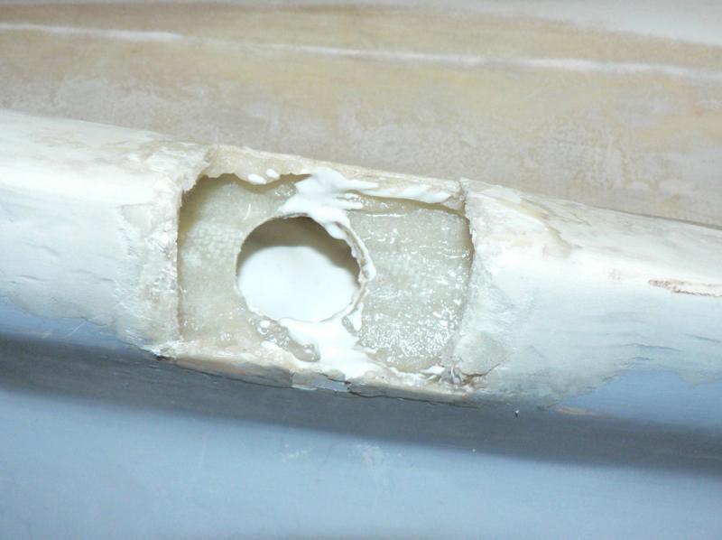
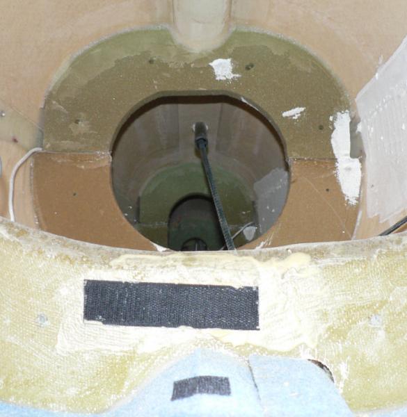
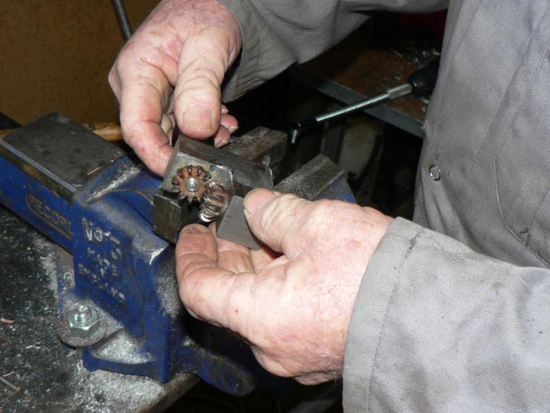
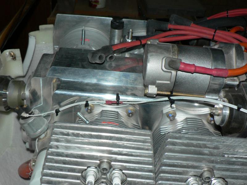
The cover over the gears was removed to see why the rotor was rotating freely. Inside the housing the back of the rotor is normally pop riveted to the non metal drive gear that picks up the drive presumably from the camshaft. Two of the four steel pop rivets are missing/failed eventually possibly allowing the gears to "de-mesh" therefore eventually stopping the left distributor firing in the correct part of the 4 stroke action. The remains of most of the missing two pop rivets was sitting on the bottom inside edge of the cover. Whether the failed pop rivets were a result or a cause of the failure is certainly not clear at this stage. The factory said they had never seen a failure of those rivets in the past. The owner says that he thought the "free play" experienced in the rotors when felt some time in the past at a scheduled inspection was excessive. His opinion of there being excessive backlash was dismissed as unlikely at the time!!
-
Today after I completed my BFR I saw an early model lonely Jab LSA on the tarmac with the top cowl removed with the owner in attendance. It turned out that this cross country pilot who had just landed to refuel always makes it a practice to check his "mags" before shut down as well as before take off. Today the check found a faulty one. It was initially thought the fault was possibly in the coil or it's earth lead had been accidentally grounded somewhere in the coil wiring system. The "mag" switches normally stop the motor by closing both switches thus earthing the lead from each of the coils. This kills the available charge in the coil. This is opposite of what we normally expect from a switch in a lamp circuit. After shutting down the good coil with the ignition switch and trying the faulty one it was firing but could not maintain the running motor without the other coil as well. The distributor cap was removed revealing the inside of the cap marked around about 180 degrees of its circumference in line with the rotor head and a fine coating of brown plastic or Bakelite like dust around most of the inside of the cap. On removal of the rotor it was found that the shaft could be easily rotated using two fingers through a full 360 degrees but still had some erratically slight connection to the rest of the engine. The pilot decided not to continue the trip or return home on one ignition system.
-
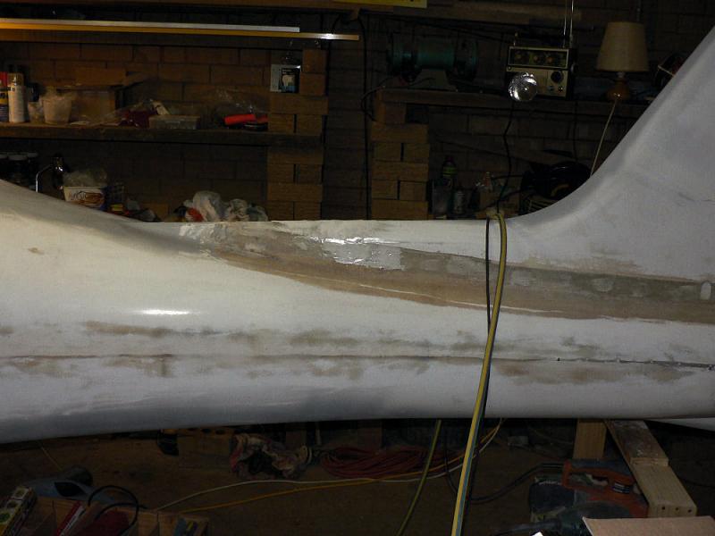
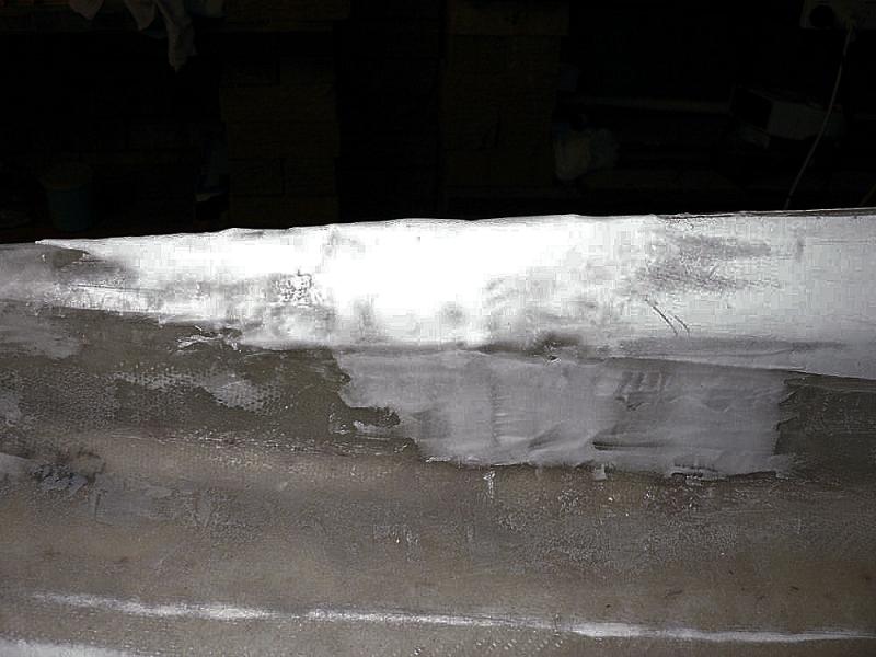
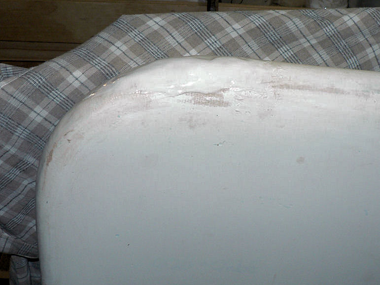
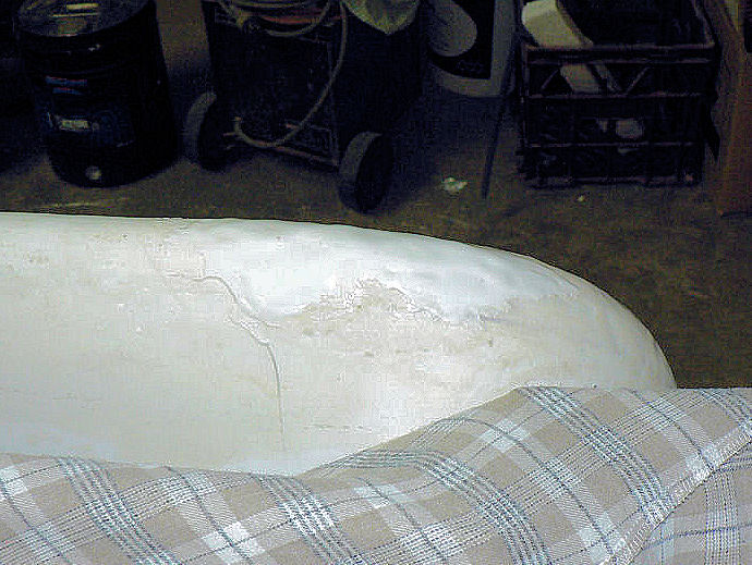
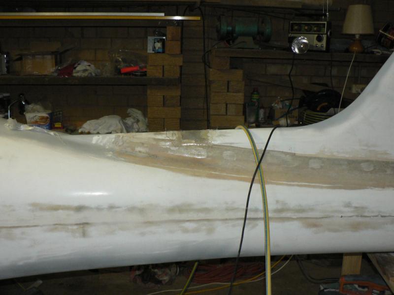
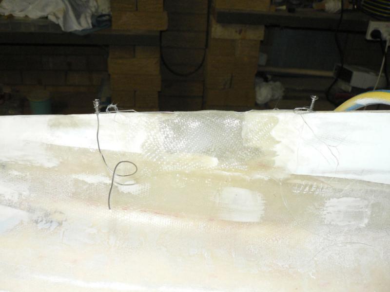
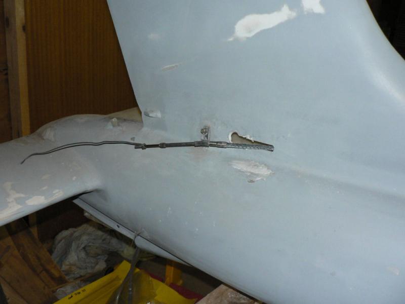
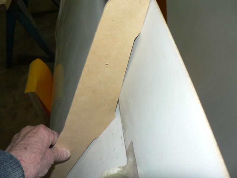
09-08-2008 Smooth up top of fuselage in tail region to repair rudder access hole and rear rudder cable exit hole. Removed SS screws scraped & sanded area around repairs. File out fill in round holes at rear for rudder cable exit & file plugs to suit. Clean up with Acetone. Prepare chipped area in RH wing leading edge that had been previously filled some time ago to conform to profile by removing any loose material and cleaning up with Acetone. It was later dropped and the epoxy-microball fill chipped. I offered the dropee a ride on the test flight but he declined. [ATTACH]6137.vB[/ATTACH][ATTACH]6138.vB[/ATTACH][ATTACH]6139.vB[/ATTACH] [ATTACH]6140.vB[/ATTACH][ATTACH]6141.vB[/ATTACH][ATTACH]6142.vB[/ATTACH] [ATTACH]6143.vB[/ATTACH][ATTACH]6144.vB[/ATTACH][ATTACH]6145.vB[/ATTACH] It will need another layer of microball fill at least to smooth up the areas. I had to change the pics drastically to cut down the flare from the bright white areas of the epoxy-microball fill especially after looking at the previous post again. 21:00 Hrs Still getting some plastic flow on curved fill areas so kneaded it back in place as required for second time at 21:00 hrs. If the fill was made drier it would not have good adhesion to the underlying surface. As well as that it is a pretty cool night so turned up about another 2 Kw in the garage and opened the door into the house so the reverse cycle can contribute some heat as well. Another hour will probably see the fill not moving any more.

-
Talk of Ceramics reminds me that the CSIRO at Hyatt I think in Vic in about the 1960's had successfully developed machineable ceramic materials for use in manufacture of engine cylinder liners, heads and pistons. I did not ever see any details except to remember that it resulted in substantial improvements in specific fuel efficiency. Speaking generally the current internal combustion engine is a very inefficient machine.
-
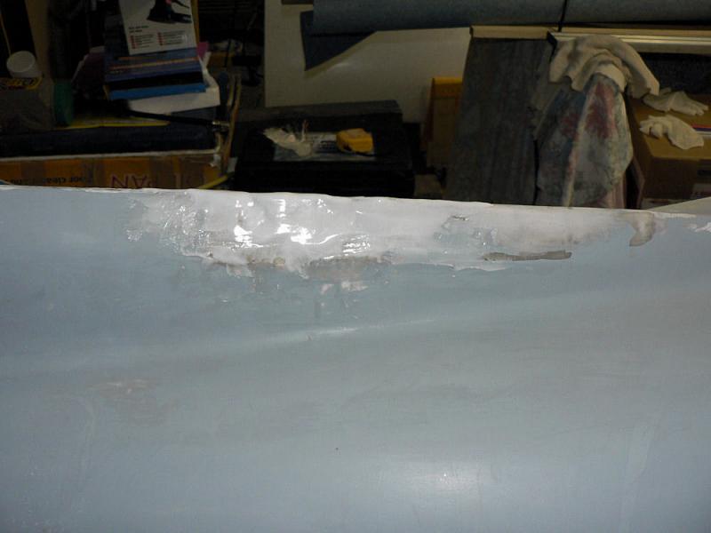
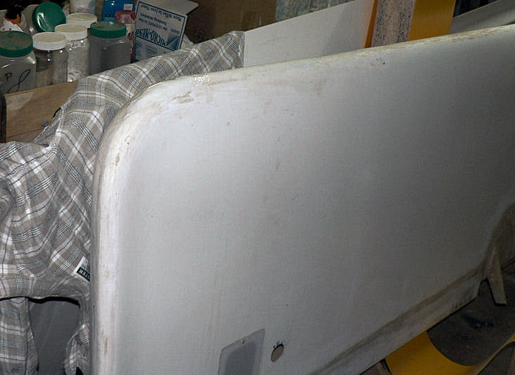
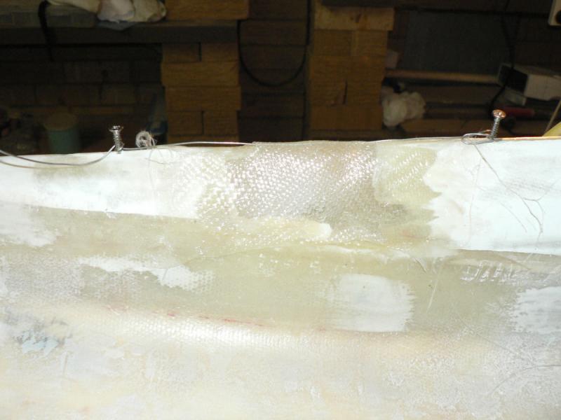
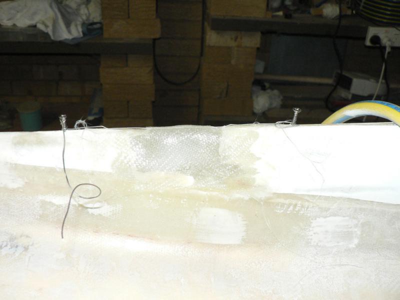
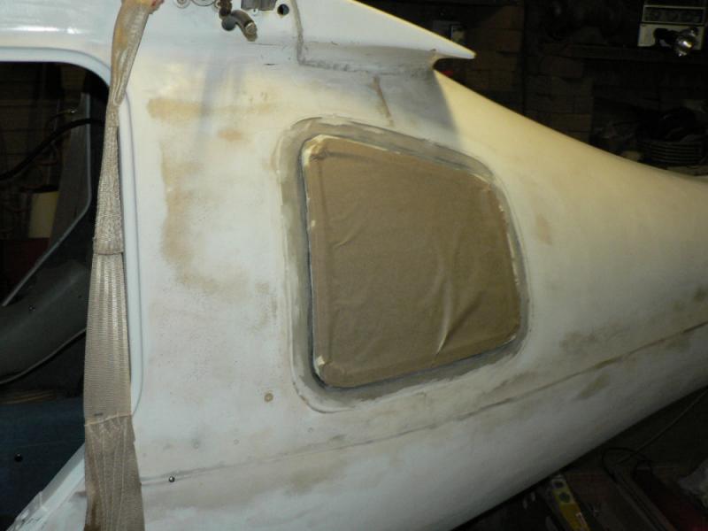
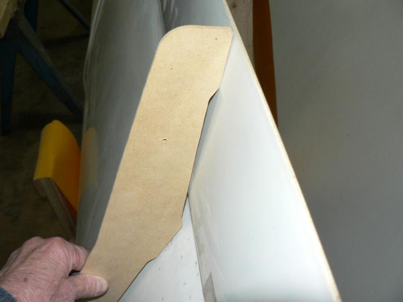
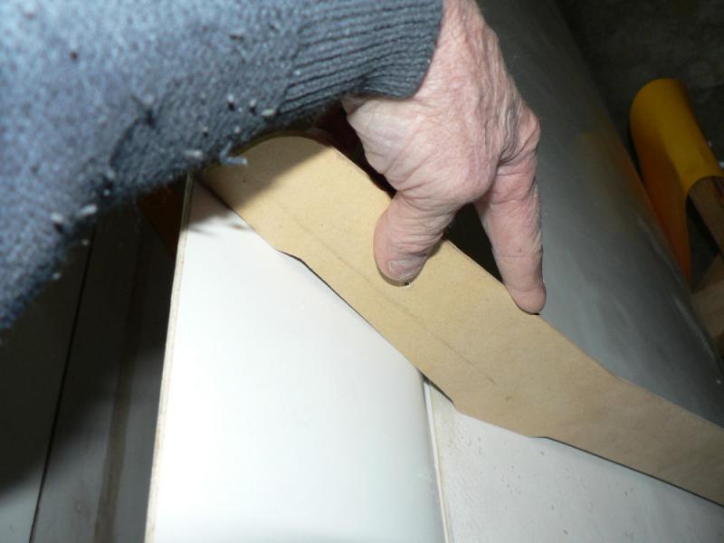
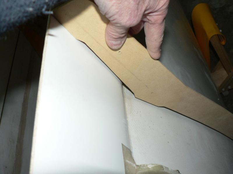
2-08-2008 Covered over access hole for rudder cable feed on top of fuselage. Used emery cloth mounted on angle grinder to remove paint and gel coat in the area of the proposed join/cover. Mixed a batch of epoxy. Cleaned proposed join area with acetone then primed with epoxy. Cut out fibre glass cloth patches to cover access hole. Applied 1st layer of cloth epoxy and press down on already applied epoxy. Applied epoxy to wet up whole cloth. Applied 2nd fibre glass layer and applied epoxy to wet it up. Squashed down edges to get a neat join. As the middle kept sagging ran a piece of SS lock wire along the apex of the cover/join to support the top. [ATTACH]6097.vB[/ATTACH][ATTACH]6098.vB[/ATTACH][ATTACH]6099.vB[/ATTACH][ATTACH]6100.vB[/ATTACH] Will trim the edges later and fill the screw holes and remove the wire. Will also need to fill over the joint using micro-ball/epoxy mix to get a smooth surface.
-
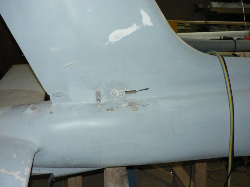
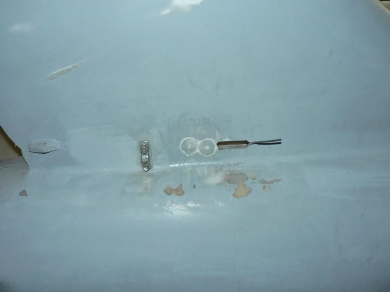
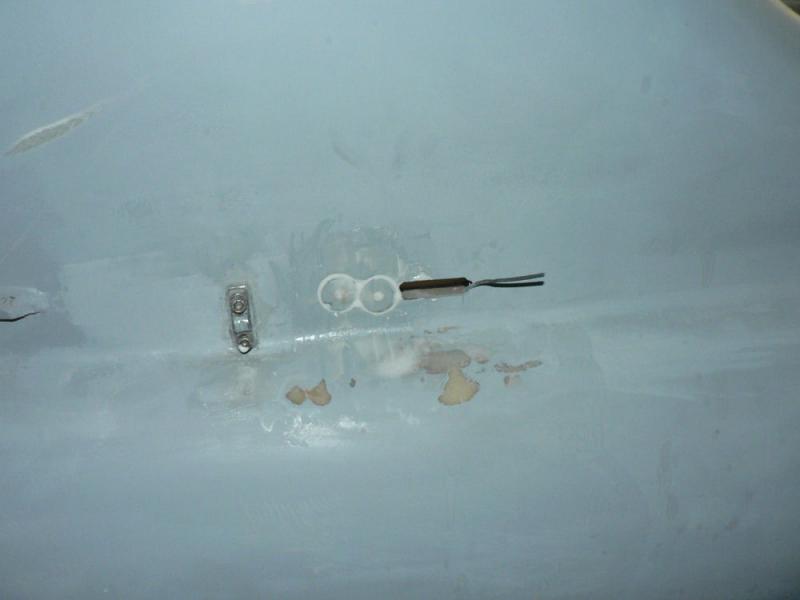
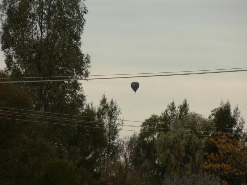
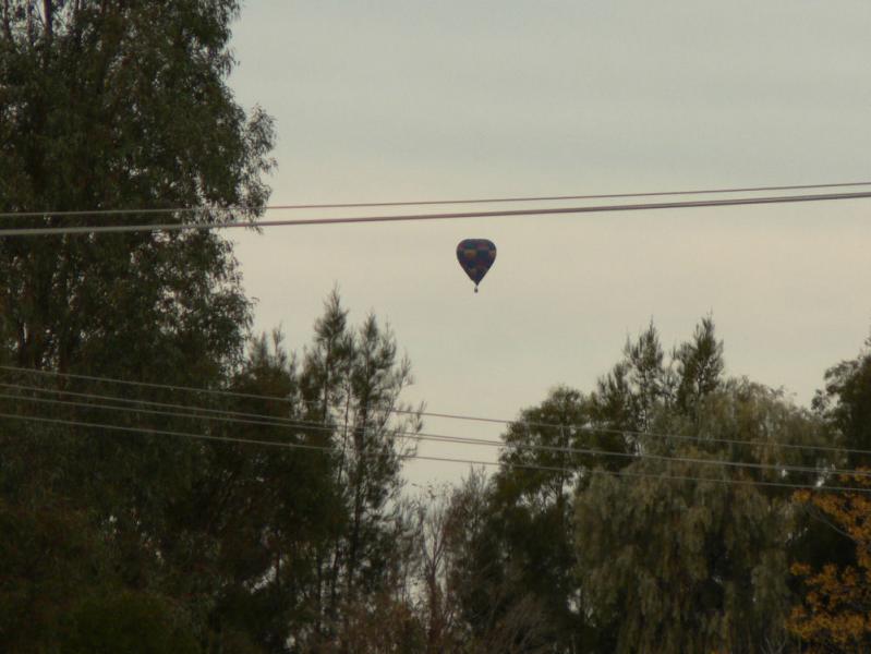
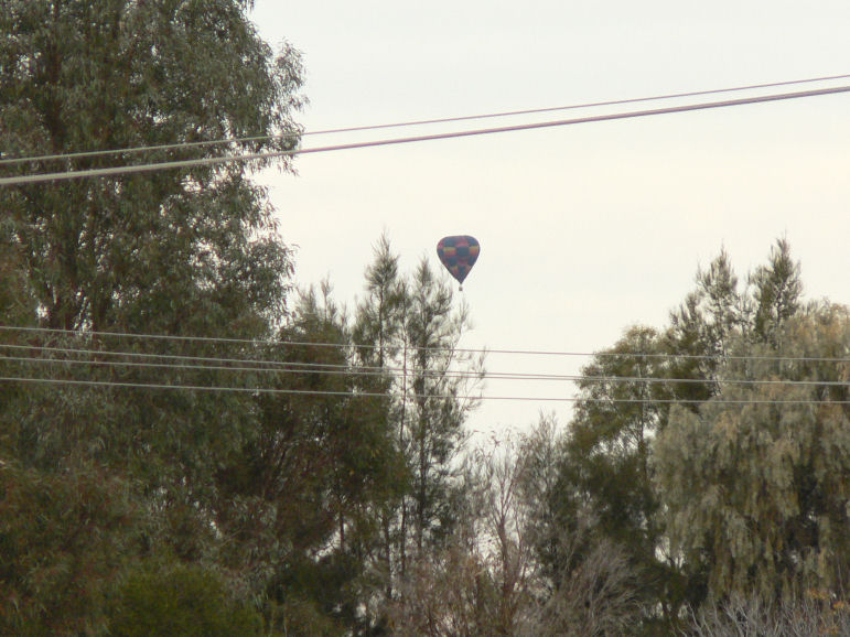
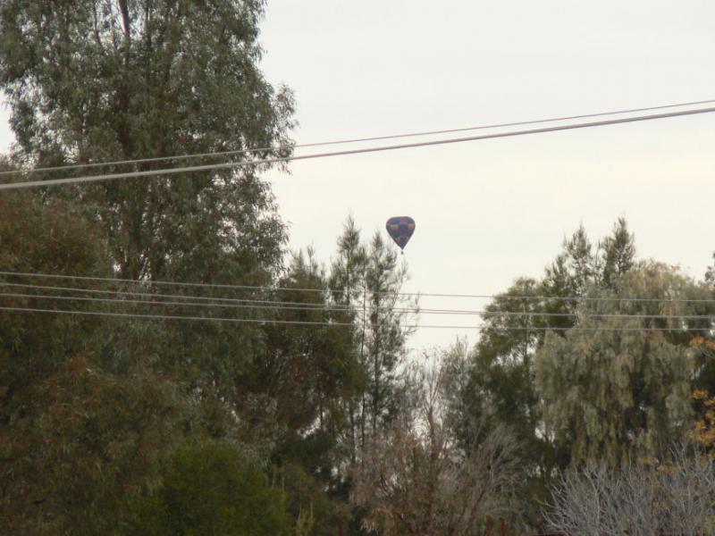
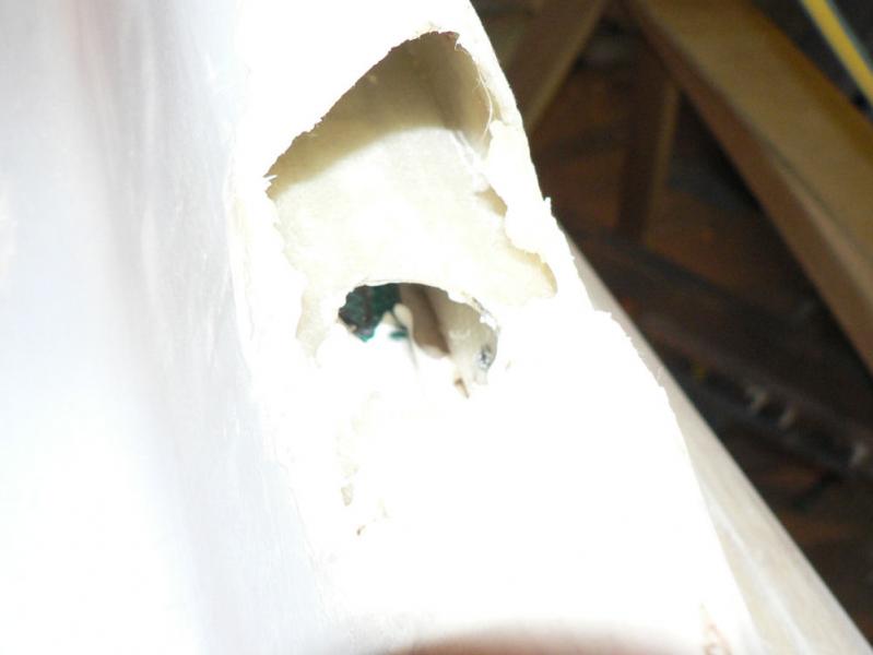
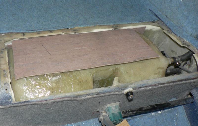
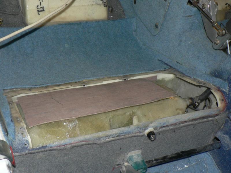
29-07-2008 Joan came into the garage to tell me that a hot air baloon was approaching our place. So I thought I'll just finish what I was doing on the J160 then go out and get a photo or two. When I got outside it was fast disappearing towards the ground to the East of town. So these pics are taken near sunset with a hand held Panasonic DMC-FZ5 with the zoom set to 12X . The camera has an anti shake feature but I also had my elbows sitting on a fence post with the camera strap around my neck. [ATTACH]6064.vB[/ATTACH][ATTACH]6065.vB[/ATTACH][ATTACH]6066.vB[/ATTACH][ATTACH]6067.vB[/ATTACH] All the baloon pics were cropped. ********************************** Cut a hole in the fuselage again in the same place as done previously when the rudder cable was fitted. Fed a piece of wire through the hole into and along the rudder cable space until the wire reached the exit hole for the rudder cable just forward of the rudder cable anchor position. Cut a piece of 3/4" hose about 600 mm long and drill a small hole into the hose at the 300 mm position. Bent the end of the wire into a slight small hook and inserted it into the hole in the hose. Pushed the hose over the rudder cable and then pushed it into the rudder cable space near the rudder cable anchor. At the other end of the wire pulled the hose through until it reached the hole where it exits the space into the fuselage behind the luggage space. Continued to pull the wire & hose while pushing the leading edge of the hose down through the access hole into the fuselage. Continue until half the hose is into the fuselage space. Removed the wire from the hose with a pair of long nosed pliers. Mixed up some microballs and epoxy into a stiff mixture and used a stick to feed it into the rudder cable space around the position of the hose exit into the fuselage. [ATTACH]6068.vB[/ATTACH][ATTACH]6069.vB[/ATTACH][ATTACH]6070.vB[/ATTACH][ATTACH]6071.vB[/ATTACH][ATTACH]6072.vB[/ATTACH] The short piece of wire on the end of the rudder cable will allow the cable to be pushed into the rudder cable space while painting takes place and then retrieved when finished. The hose will protect the cable from damage chafing on the fuselage fibreglass and make it easier to insert a new cable when it is due to be replaced.
-
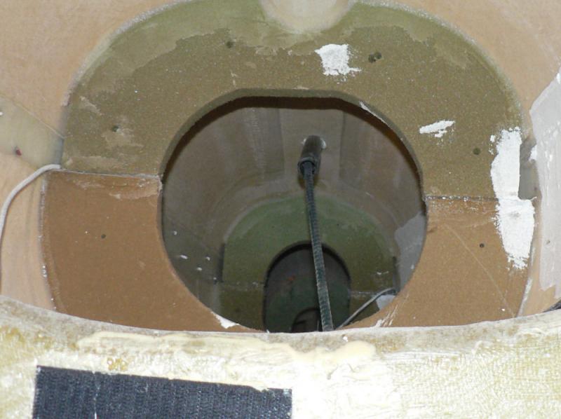
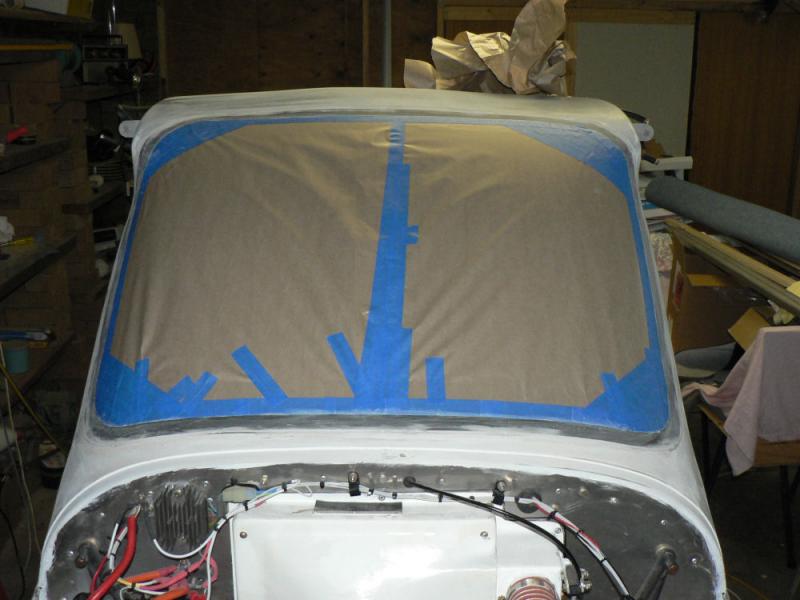
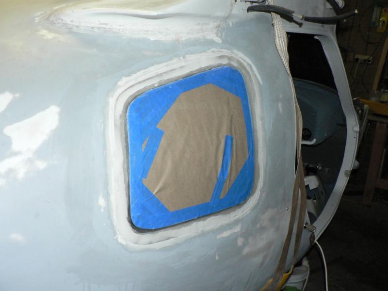
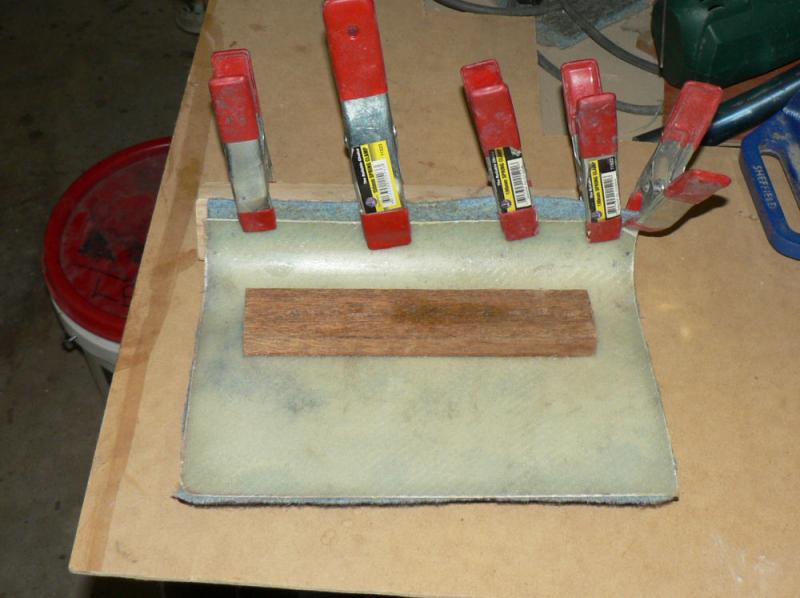
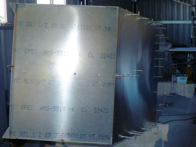
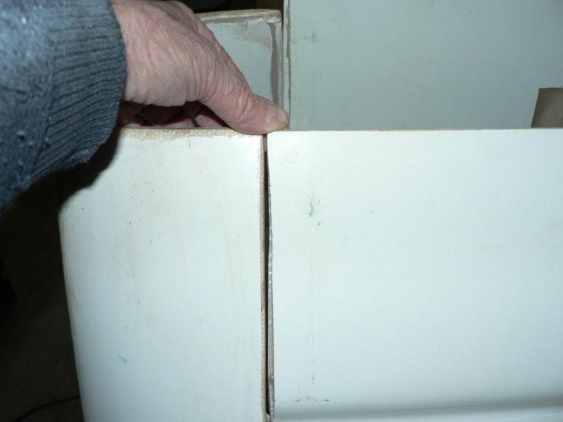
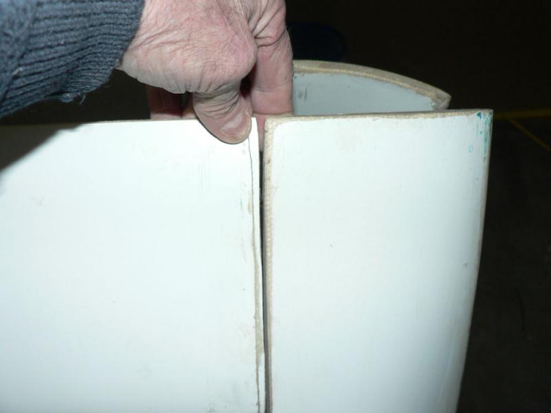
26-07-2009 Removed clamps from header tank cover and sat the header cover over the tank in the starboard seat pan. Masked the two fuselage windows using 3Mtape and brown paper. Masked the windscreen using masking tape and brown paper. [ATTACH]6061.vB[/ATTACH][ATTACH]6062.vB[/ATTACH][ATTACH]6063.vB[/ATTACH]
-

Arrest made after laser attack on pilot
Ross replied to Ben Longden's topic in AUS/NZ General Discussion
There are plenty of ground based lasers used to control earthmoving equipment, control mining excavations, pipe laying etc. They could be used as fixed pointing beams or used with rotating beams forming a reference plane. In the case of "land forming" for irrigation farms these are usually 5 milliwatt red rotating lazers mounted on towers about 5 metres above the ground. They usually have warning signs on them to warn against staring into the transmitter. The ones I have seen in the past worked fairly accurately out to 300 metre radius and sometimes effectively out to about 4 or 500 metres radius from the transmitter depending on conditions. The beam is detected by a receiver mounted on a mast that can be extended a similar distance above the working surface or retracted to a shorter length when constructing an embankment like an elevated bank or a roadway. To excavate more depth the the mast on the excavator would be extended so that it could reach the beam as the hole got deeper. It made a great deal of difference to these transmitters or rather the quality of the lase beam if the transmitter could be mounted on a tower so that all erratic movement of the tower (and beam) was damped out when set up and working. This is not all that easy to do. Because of the normal scattering that a laser beam usually encounters due to the air it encounters and the dust and possible other particles in the air the beam starts to diverge and looses its energy concentration and its ability to trigger the receiver electronics. In these instruments I think the starting diameter was about 15 mm but uses a lens to make it come down a cone which has already opened up again to something like 12 mm at around 300 metres radius from the transmitter. But at that distance there is already a significant loss of power even though the beam is still only about 12 mm diameter. As you get out further the scattering of the beam by the gunk in the air makes the beam diverge more and more. The effective work done by the reducing power applied on any target in this situation gets less and less. This work done by whatever power is left in the beam is further reduced as the radius increases because the time the beam is on any particular target gets less as the radius increases provided that it is a rotating laser, typically 300 RPM or 600 RPM with one I was familiar with. Of course a non rotating beam from a pointer is an entirly different matter. You could often see flashes from these rotating transmitters from public roads at night while driving in irrigation farming areas from some kilometres away from the transmitter. They appear as unexpectantly bright flashes that your brain tells you that you do not want to continue staring at the source. So they are hardly likely to be prevalent enough to be a real nuisance or distraction. I guess this is because a lazer beam is not a constant beam of energy. It is a bit like being hit by a hammer say once every 24 hours verses being pushed by a butterfly for 24 hours straight. But the pulses are so fast that our brains would probably interpret them as a constant beam of very bright light. Either item might be applying the same total amount of energy on you per day or per hour but possibly you might only notice one of them. Due to the angles of the plane the beam is usually set at, the maximum allowed power of the laser (usually 5 milliwatt), the natural divergence and diffraction of the beam, the curvature of the earth and the height and size of the beam it may never be a problem. Please excuse my rambling. It's a bit past bedtime I just noticed.. -
Hi Peter I just looked at your pic and it appears that you have a fibreglass aeroplane and unless it is covered in metal it occurs to me that it might be easier to install an internal dipole aerial if you have the vertical space. I just ducked out to my garage to get an approximate total length from top to bottom of the aluminium dipole aerial installed in the tail of my J160 kit. I think dipole aerials have a better rating than 1/4 wave aerials and do not waste as much power by radiating a signal basically in a ball shape. A dipole aerial basically radiates most of its energy out horizontally - so there is an advantage in mounting it so that it stands vertical in the ac when in flight although it operates OK in the Jabiru when mounted in the back of the vertical stabiliser which is on a small angle to the vertical. A dipole aerial does not need a ground plane and consists of two legs with one connected to the core wire of the coaxial cable and the other leg to the outer sheath of the coaxial cable. Jabiru specify which wire to connect to the top element of the dipole and which coaxial part to connect to the bottom element of the dipole. They are normally not connected electrically but I think they can be provided a suitable resistance is in the circuit. So normally a dipole aerial cannot be tested for continuity from the radio end unless a single extra wire is run from there back to each of the dipole elements during the test with the coaxial not connected to the radio. I think there was an article on this subject in a Pacific Flyer magazine quite some time ago. If they were connected electrically they can be tested for continuity with a multimeter as you can do from the radio end with a multimeter on the disconnected coaxial at the radio end of a coaxial cable connected to a normal 1/4 wave aerial with a ground plane.. The total dipole is slightly less than 980 mm overall length with a gap in the middle of 12 mm I think. The middle gap is critical as is the length of each element of the dipole aerial which is just two thin strips of aluminium on my ac. I could get more accurate measurements in daylight if you want them and check out the specified gap from the Jabiru construction manual. This aerial was set up for the early radios in the jab which did not have the weather frequencies so there might be a slight difference in an aerial to handle the ATIS frequencies as well. I do not know. Regards
-
Hi Steve I think the J170 has a lower stall speed than the J160 and the J230 making it a better short field performer than the J160 and the J230. Supposedly the J170 has the wings of the J230 i.e. longer than the J160 wings so that it complies with USA stall speed rules and RAAust. The J230 is nicer to fly than the J160 and the J170 being heavier and with a flat 6 cyl 3300 cc motor flies about 15 to 20 knots faster burning about 6 more litres per hour than the other two. The motors are the same for the J170 and the J160. A flat 4 cyl @ 2200 cc. The J230 is obviously going to cost maybe 50% more than the J170 or J160 to do a top overhaul at 1000 hrs or a major at 2,000 hrs. The J160 has a lower climb performance than the J170. I think Jabiru recommend a climb speed of 80 knots to keep the oil temp down. I am slowly building a J160 which hopefully will fly before Christmas (this year folks).
-
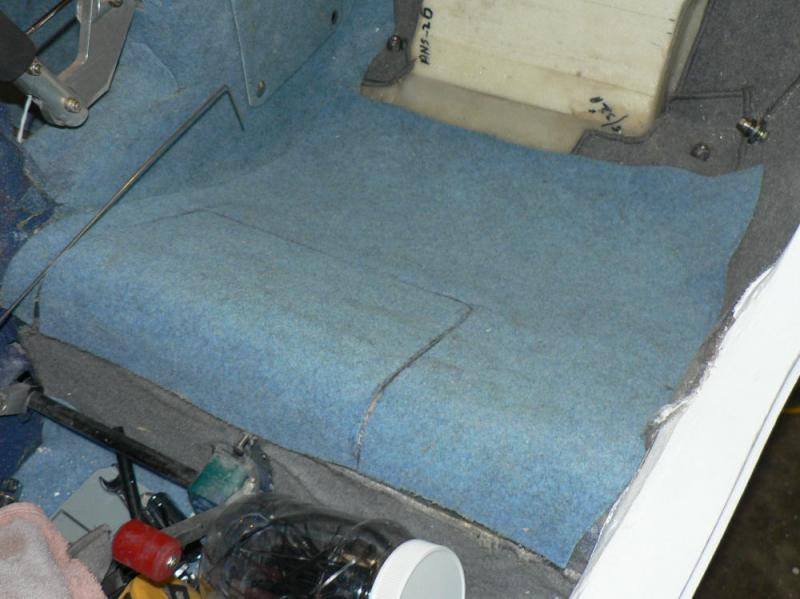
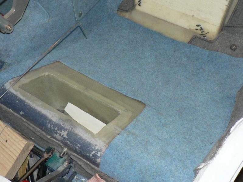
25-07-2008 Measured felt & cut to suit header tank cover for starboard side. Applied adhesive to cover & felt after marking and cutting felt to suit cover holes for screws into the six retained nuts in the seat pan. Weighted and clamped felt to header tank cover for starboard side. Removed clamps from toolbox lid and fitted lid to top of toolbox under pilot seat pan. [ATTACH]6036.vB[/ATTACH][ATTACH]6037.vB[/ATTACH][ATTACH]6038.vB[/ATTACH][ATTACH]6039.vB[/ATTACH]
-
What really appeals is seeing a large post followed by half a dozen others containing the same post as a quote. Regards
-
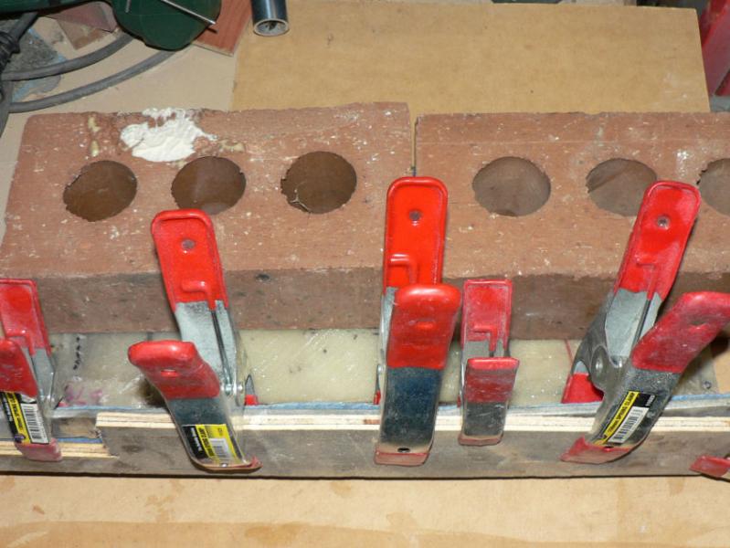
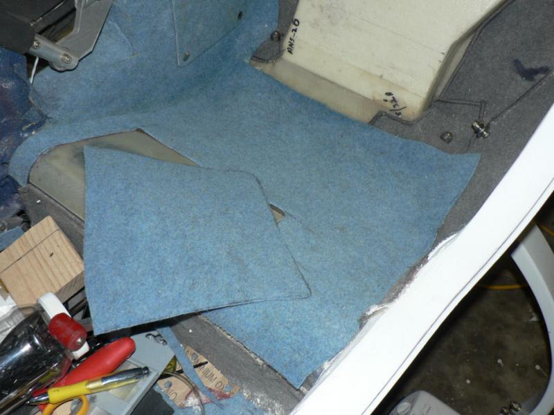
24-07-2008 Applied felt to toolbox lid for pilot side. Applied felt to port side seat pan after measuring making out and cutting out a piece of felt. Used spring clamps to hold felt in place. Still to do felt on header tank cover Header tank has packing around it to prevent fibreglass to fibreglass contact in the header tank space including the lid. [ATTACH]6033.vB[/ATTACH][ATTACH]6034.vB[/ATTACH][ATTACH]6035.vB[/ATTACH]
-
23-07-2008 Decided to tidy up the seat pan felt and had just marked out the base of the first one when a visitor arrived. So just applied adhesive to first area and the felt and sat it in place. I don't think the visitor was very impressed with the Jabiru seat until he saw the sheep skin padded seat covers which fit over the seat pan and the back rest. He then remarked that he might try and do something similar for his a/c. The loose piece of felt sitting on top will be glued to the bare space under it which is the cover over the pilot side tool box. Normally I wash the brush out in water but it does not get it completely clean so tried acetone which does not dissolve the sticky residue. Tried "Turps"! Worked well and can be used on the felt with a rag to remove excess outside the target area. [ATTACH]6030.vB[/ATTACH]
-
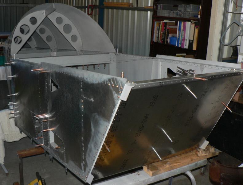
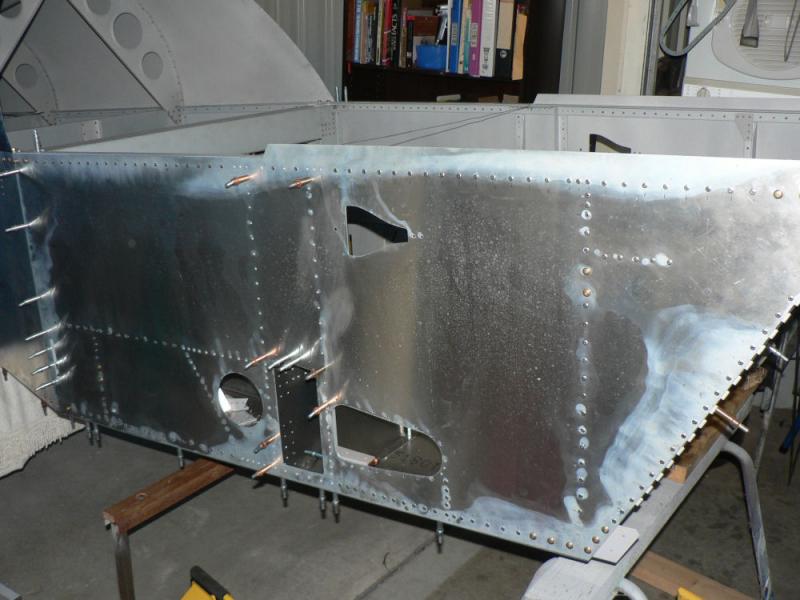
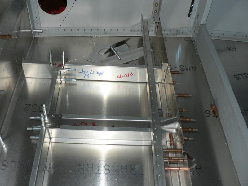
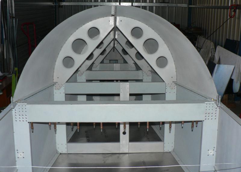
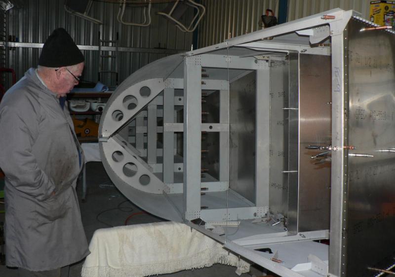
22-07-2008 Thanks Ian for the well wishes. Went round to Warren's for a Sonex roll over this morning. Warren is surging along with his Sonex build and needs to have better access to the cabin area so we rolled it over on a set of trestles which gives him better access to the cabin and firewall area. He has plenty to do on the build yet but is also waiting on some "firewall forward" pre-fabricated parts from the USA. Most of the cabin forward construction is temporarily held together with clecoes as is the rest of the turtle-back and needs to have many more parts fitted and drilled for riveting. Most of that involves pilot holes and could possibly involve dimpling or countersinking the rivet holes as well. So there will be a new set of holes to de-bur, material to prime and then to reassemble, rivet and bolt together. One of the pics shows a right angle drive Warren was in the middle of constructing when I arrived this morning to facilitate the drilling of about half a dozen holes in difficult access areas near the front of the aircraft. [ATTACH]6022.vB[/ATTACH][ATTACH]6023.vB[/ATTACH][ATTACH]6024.vB[/ATTACH][ATTACH]6025.vB[/ATTACH] [ATTACH]6026.vB[/ATTACH][ATTACH]6027.vB[/ATTACH][ATTACH]6028.vB[/ATTACH]
-
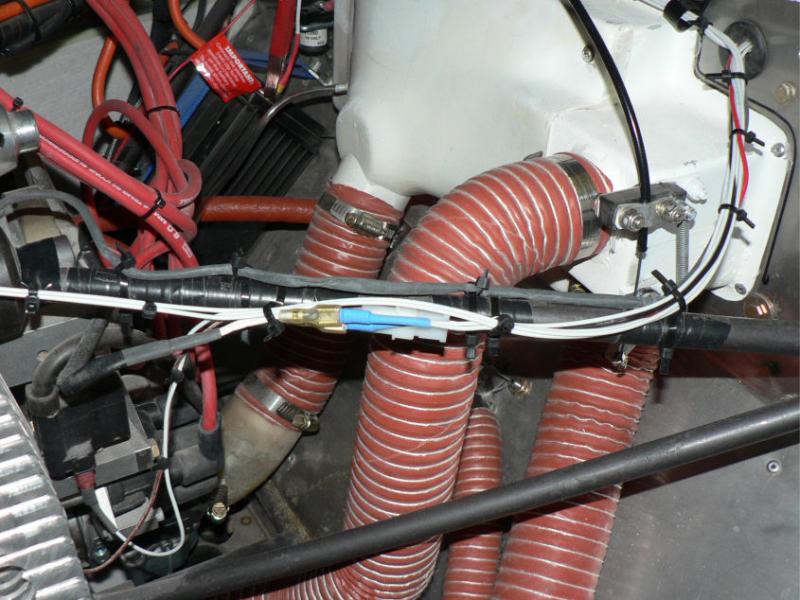
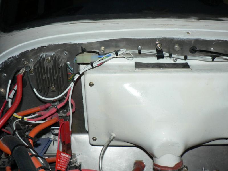
21-07-2008 Checked and adjusted aileron to wing clearance on top of aileron leading edge to wing clearance and outer end aileron to wing outer end clearance. Also used template to ensure full travel of up aileron before any binding between aileron and wing. Aileron photos show deflection past the limit of the template before any binding. Removed spiral pvc wrap around wiring in engine bay as regard as a fire hazard after lighting a sample with a lighted match. It lit up and was self sustaining dripping hot burning PVC. Removed stand offs and used two cable ties at each anchor point instead where there were a number of small wires. [ATTACH]6013.vB[/ATTACH][ATTACH]6014.vB[/ATTACH][ATTACH]6015.vB[/ATTACH][ATTACH]6016.vB[/ATTACH][ATTACH]6017.vB[/ATTACH] [ATTACH]6018.vB[/ATTACH][ATTACH]6019.vB[/ATTACH][ATTACH]6020.vB[/ATTACH][ATTACH]6021.vB[/ATTACH] .
-
I usually use all the significant figures or decimal places available on my calculator - in this case ten. When you get to a number that you are going to fly too or use in some way round it off to a sensible number of figures. If that number has to be used for further calculations use all previously available digits unless you can see that it is not necessary. Recording of flight distances rounded off to the nearest mm is obviously going too far. Like a planning sheet I would round up all distances to the next Nautical mile which will help with the safe calculation of fuel reserves required but might not help if you base future fuel consumption on the rounded up distance calculated. In the case of computer calculated values special care has to be used by the programmer in setting up the calculation method in the original computer program due to the nature of binary arithmetic being used to calculate decimal numbers. Quite huge errors can be introduced by believing the computer generated answer.
-
Using your 360sx60=21600 Nmiles Divide by PI to get diameter 21600/Pi=6875.493542 NMiles Radius =D/2= 3437.7466771 NMiles approximately = 6370.777312 Km
-
According to the website below http://en.wikipedia.org/wiki/Earth_radius the equatorial earth radius is 6,378.137 Km and the polar earth radius is 6,336.75 Km Using Pythagarus to calculate the hypotenuse then at equator for the 1 km level the curvature difference calculation Hypotenuse = sqrt((6378.137 x 6378.137) + 1) = 6378.137078 km Difference = Hypotenuse - earth radius there = 6378.137078 - 6378.137) Km = 0.000078 Km = 0.078 metre ( Curvature error at equator only based on 1 km sitting on a level line ) I wish I knew that years ago when I had to write a Fortran program to do the scoring and reporting at the Gliding comps held at Leeton with latitude and longitude of the turn points and out landing positions as the only input into distances calculated. There was no one that I knew of to help. I eventually assumed the earth was a sphere of some diameter between the diameter at the equator and the diameter at the poles which I cannot remember and then used polar geometry to calculate distances. Time input was in start and finish times in hours, minutes and seconds and had to be converted to decimal hours in the program. All results had to show the input data so it could be verified if challenged. I just recalled I think that I would have used the formula for distance as Distance of a leg (arc of a circle) = Rad of earth x angle in radians from start & finish point of each leg to centre of the earth I just found a few days ago that many units of measure used would have all been redefined by agreements by international standards committees around about that time. Not to this day has anyone wanted to argue over the results that I know of. I suppose that for most situations my errors in distance would probably not have made any difference to the final results except for minor differences in distances travelled and the speeds achieved. I think there was at least one contender for a world record speed as it was a period of intense thunderstorm activity with the safety officer threatening to resign during the competition. That program eventually disappeared in a computer crash or a hardware or software upgrade.