Ross
-
Posts
729 -
Joined
-
Last visited
Content Type
Profiles
Forums
Gallery
Downloads
Blogs
Events
Store
Aircraft
Resources
Tutorials
Articles
Classifieds
Movies
Books
Community Map
Quizzes
Videos Directory
Everything posted by Ross
-
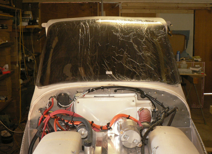
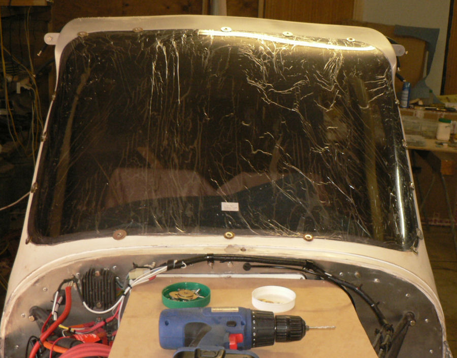
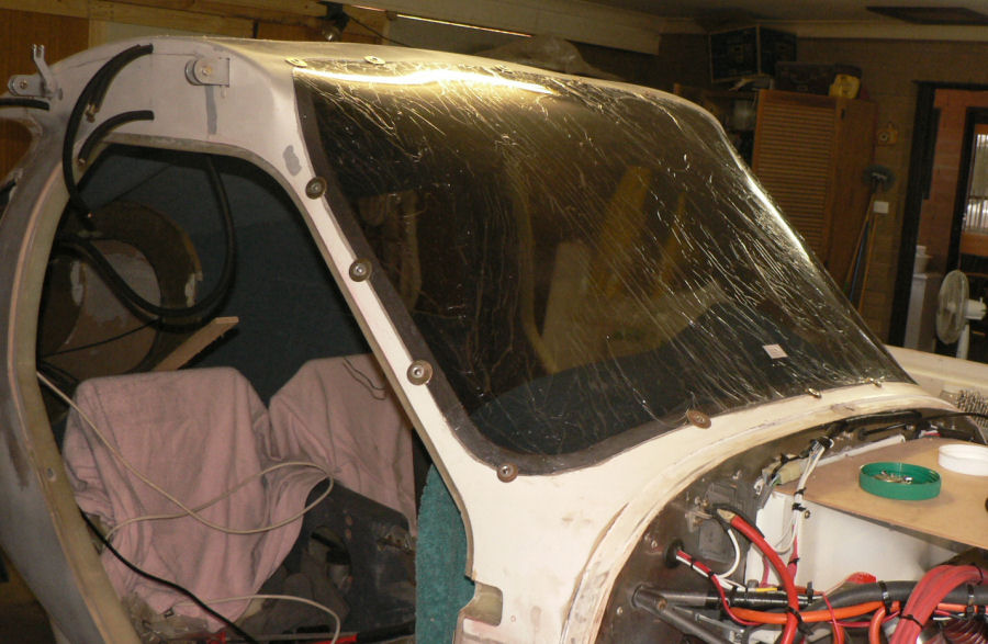
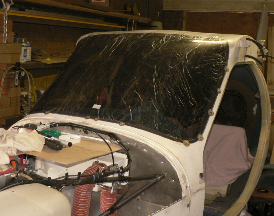
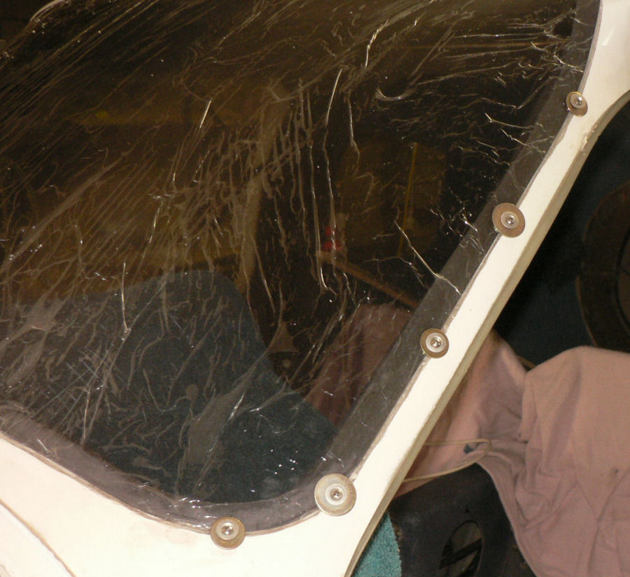
17-02-2008 Well I have not disappeared. I have a problem with the epoxy as in a number of places it moved up under the plastic covering of the windscreen and windows. As a result I have to remove it without making the screens opaque. I should have removed the plastic covering before the epoxy cured completely and wiped off the epoxy leaks with a rag and acetone.:confused: With some of the marks, the first problem is to decide which side of the screen has the mark on it. With some advice from Neville White, a local L2 with many years of experience, the problem will be eventually solved. I can see a lot of my elbow grease and additional time being used up on this part of the job. Will report again when I make some significant progress here.
-
Hi Geoff All I can say is congratulations for a well deserved magnificent job.;) Green text for envy. Regards
-

Electronics Project - audio mixer for headsets
Ross replied to sain's topic in Aircraft Building and Design Discussion
Hi Sain I admire your fortitude. It is apparent to me that there must be a fair bit of opportunity for development of instruments especially for the experimental market and a number of people are starting to show an interest in developing more competitive electronic instruments for this market. Your idea on the CHT front sounds good but with plenty of competition already unless you can get the price down dramatically. Another one I had thought of was a continuous record/display of the cylinder head pressures over the compression and firing cycle of a cylinder in the engine and/or even of all the four strokes of each cylinder in the engine. I don't know if pressure transducers are available that can respond to the cycle speeds and temperatures of the engine. Then there is the problem of inserting one in each head and the effect that might have on the combustion chamber. From a dim memory I think the combustion pressures can be over 1,000 psi or approximately 7,000 kPa. One of my pet gripes about Bright LEDs and other electronic displays is that they get very annoying when there is low ambient light outside. They all need adjustabe/automatic brightness and many are nowadays to allow for viewing from a bright sunshine condition to almost darkness so that they do not affect the vision of the outside of the vehicle. Regards -
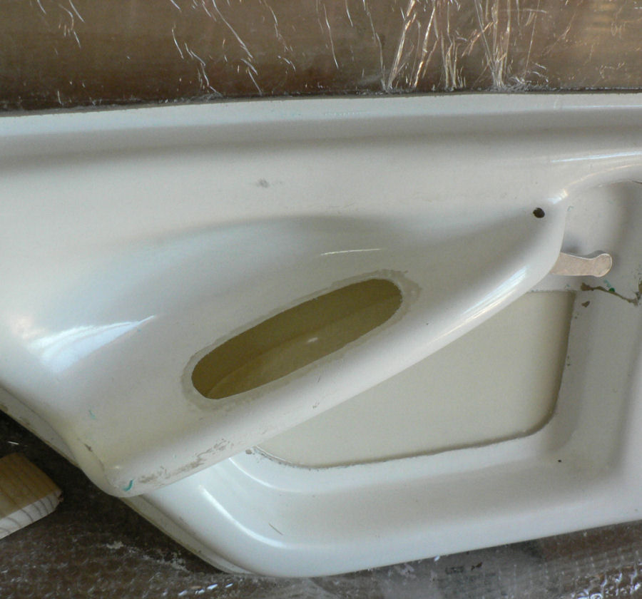
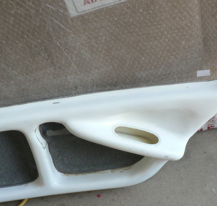
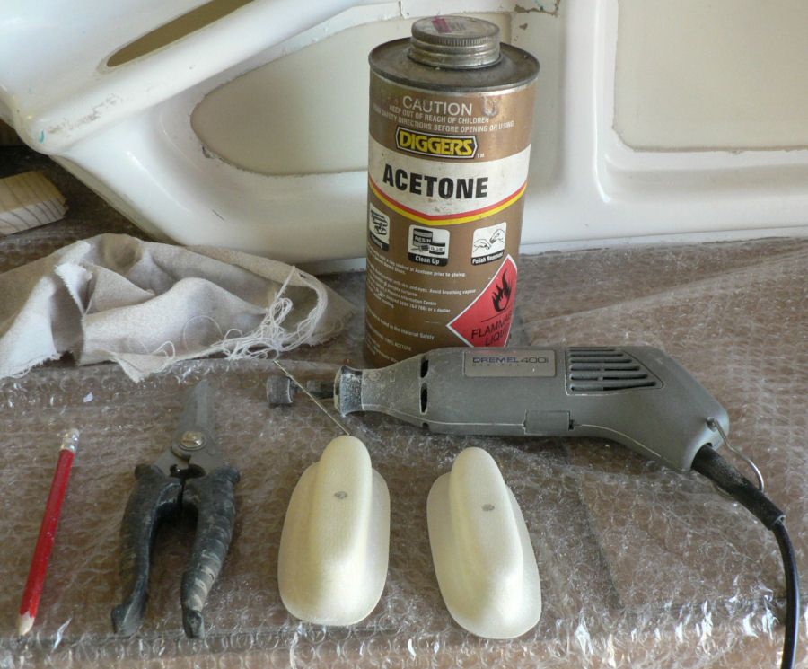
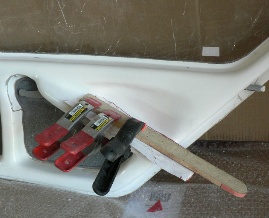
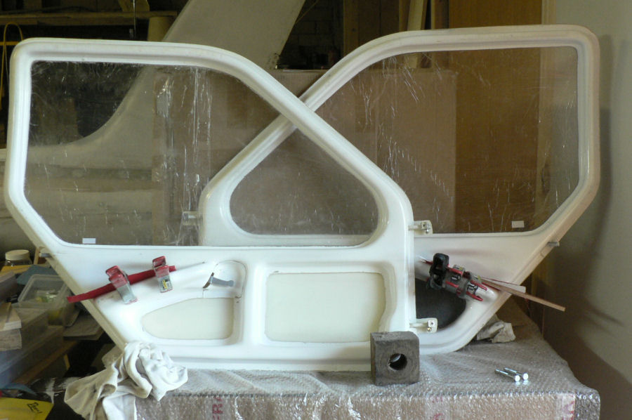
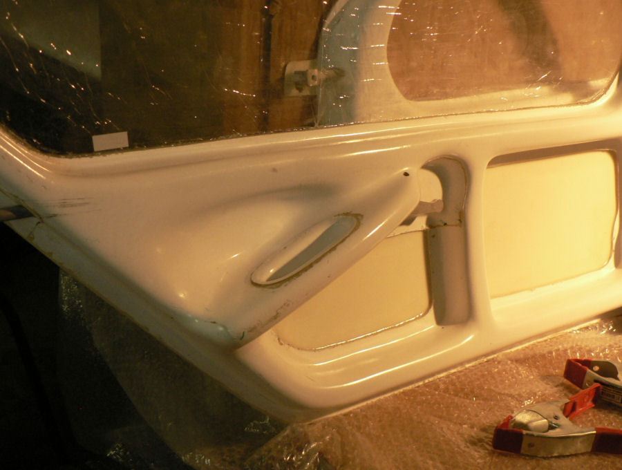
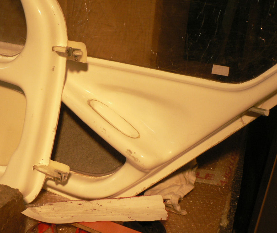
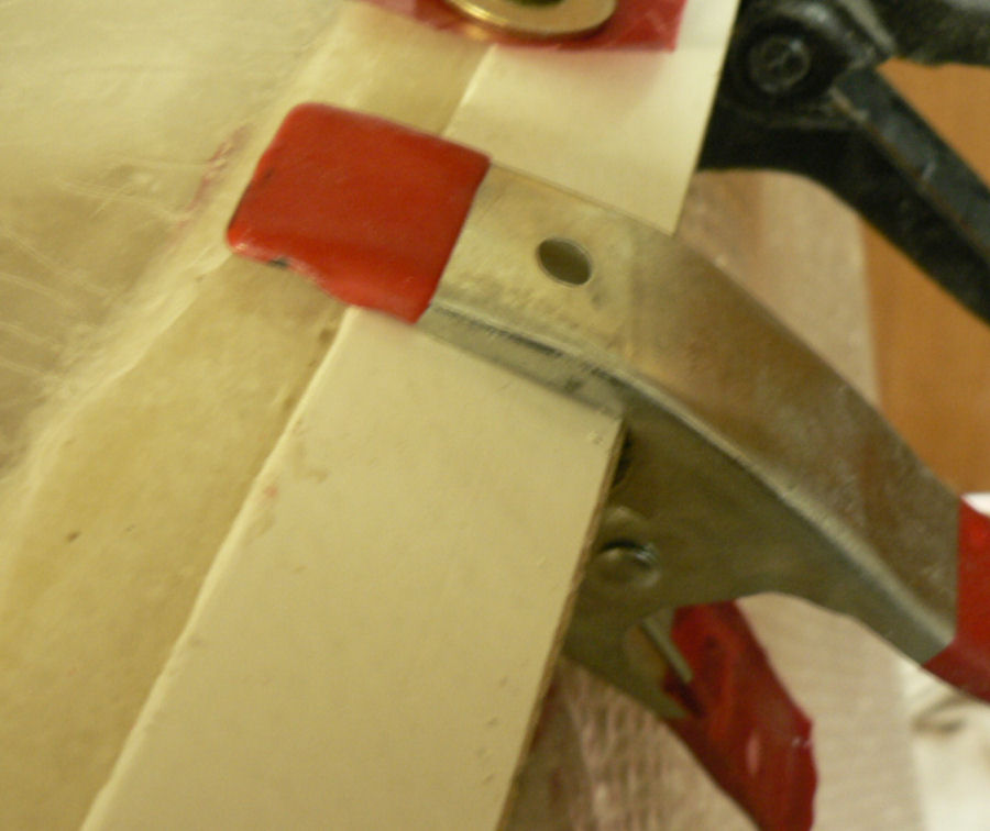
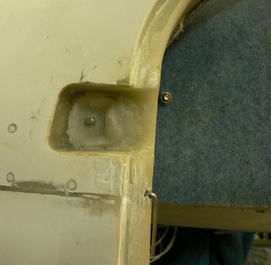
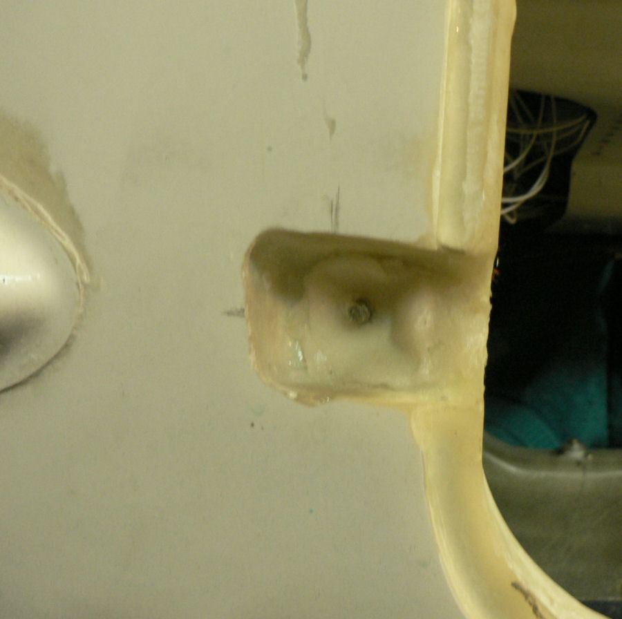
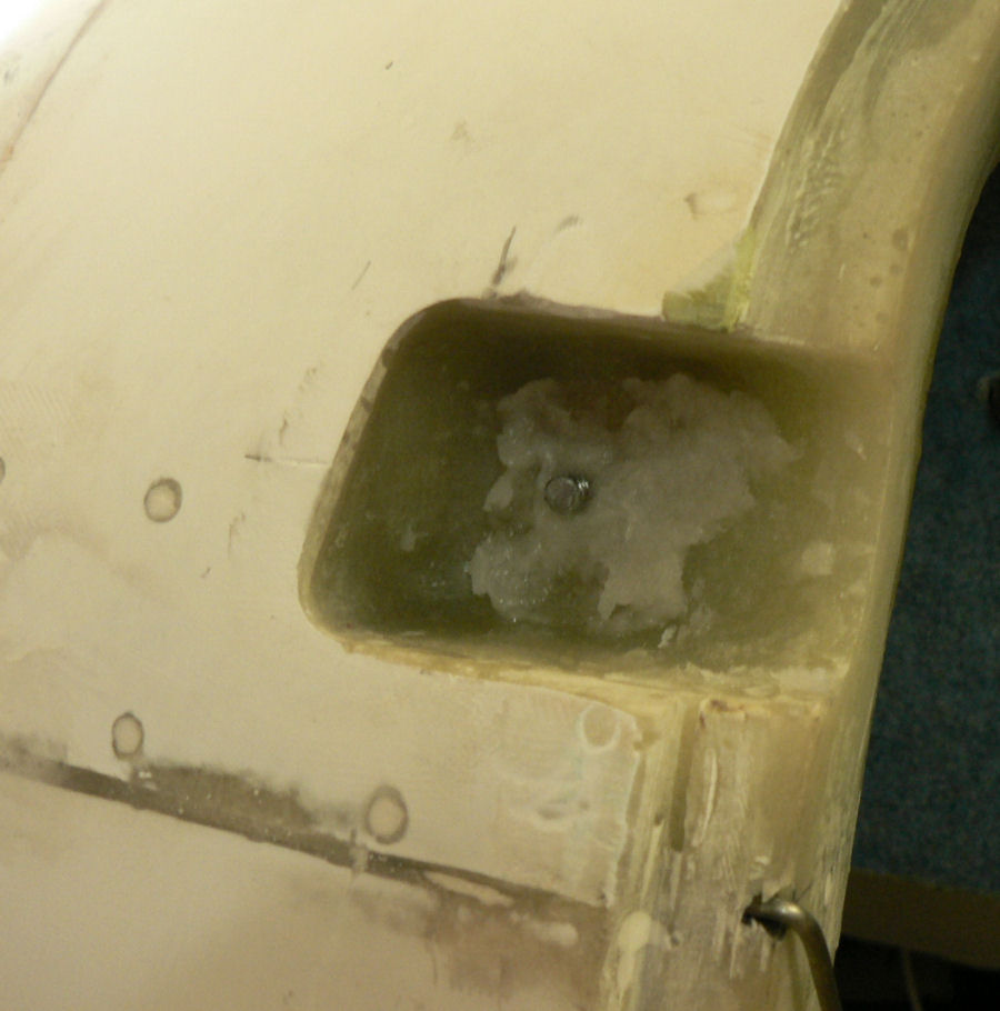
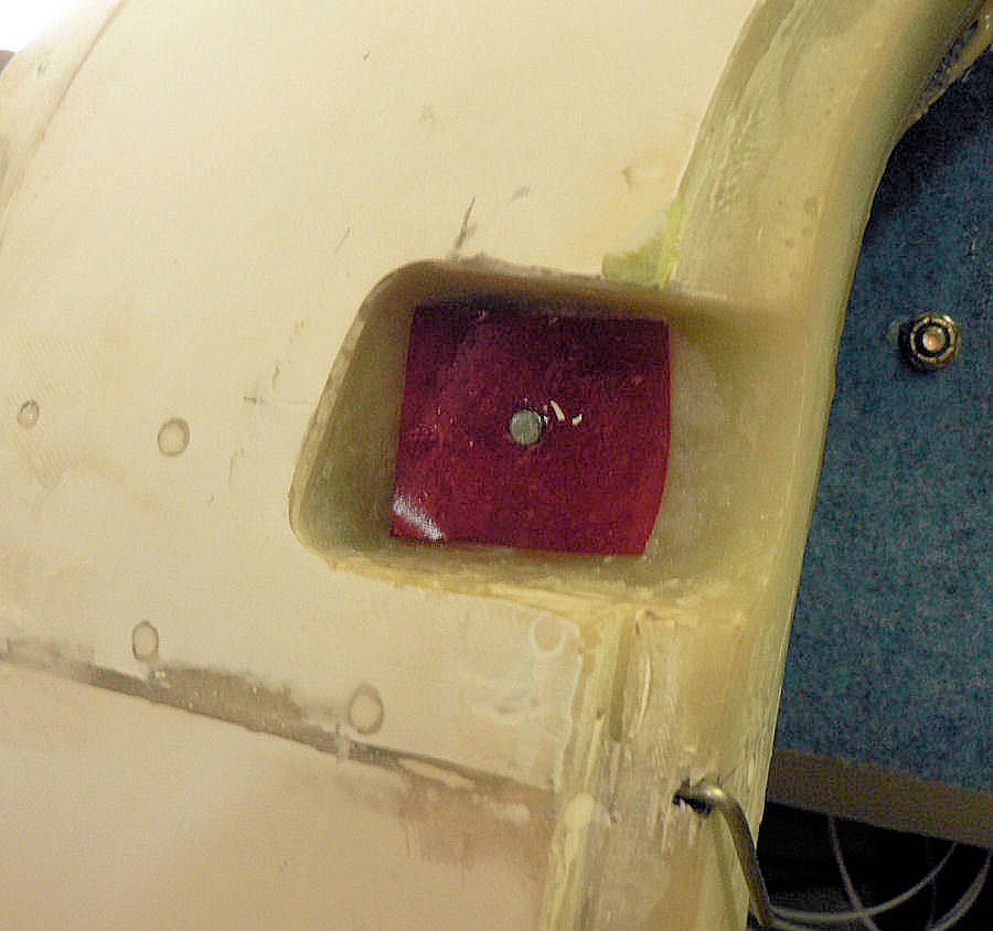
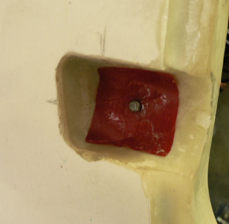
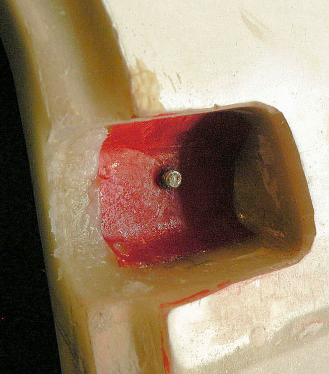
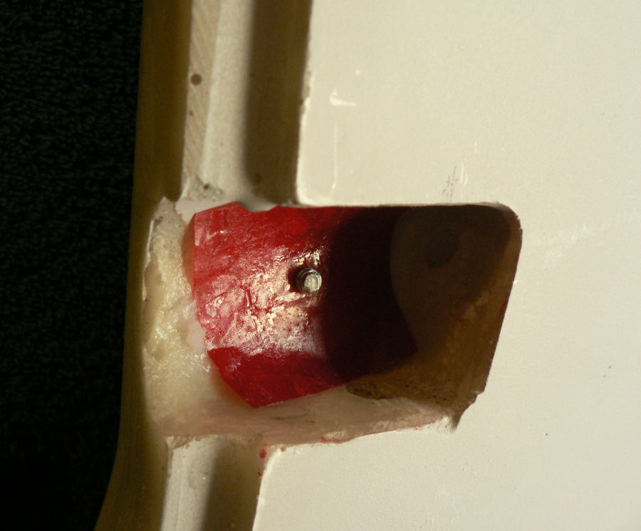
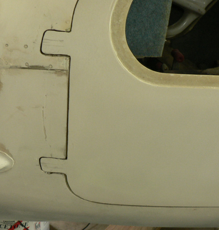
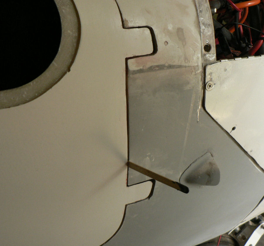
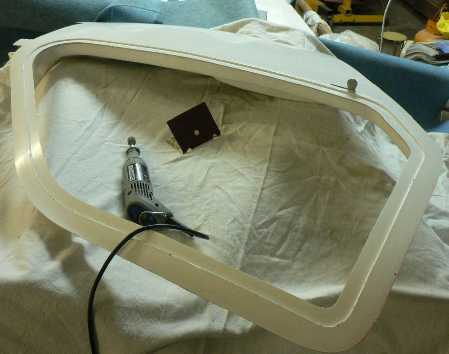
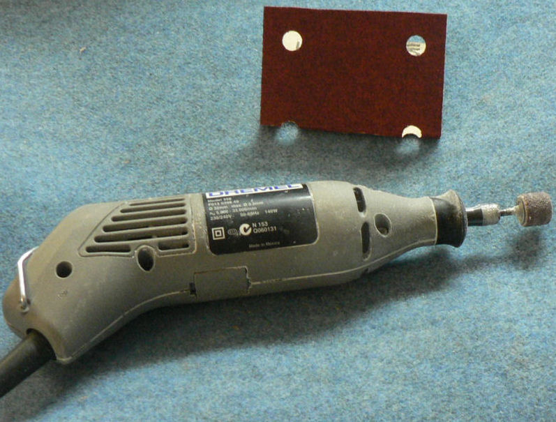
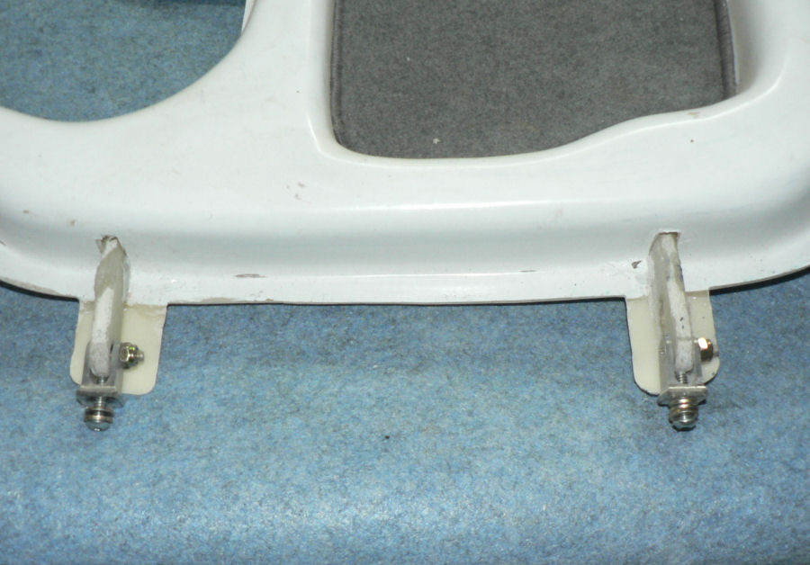
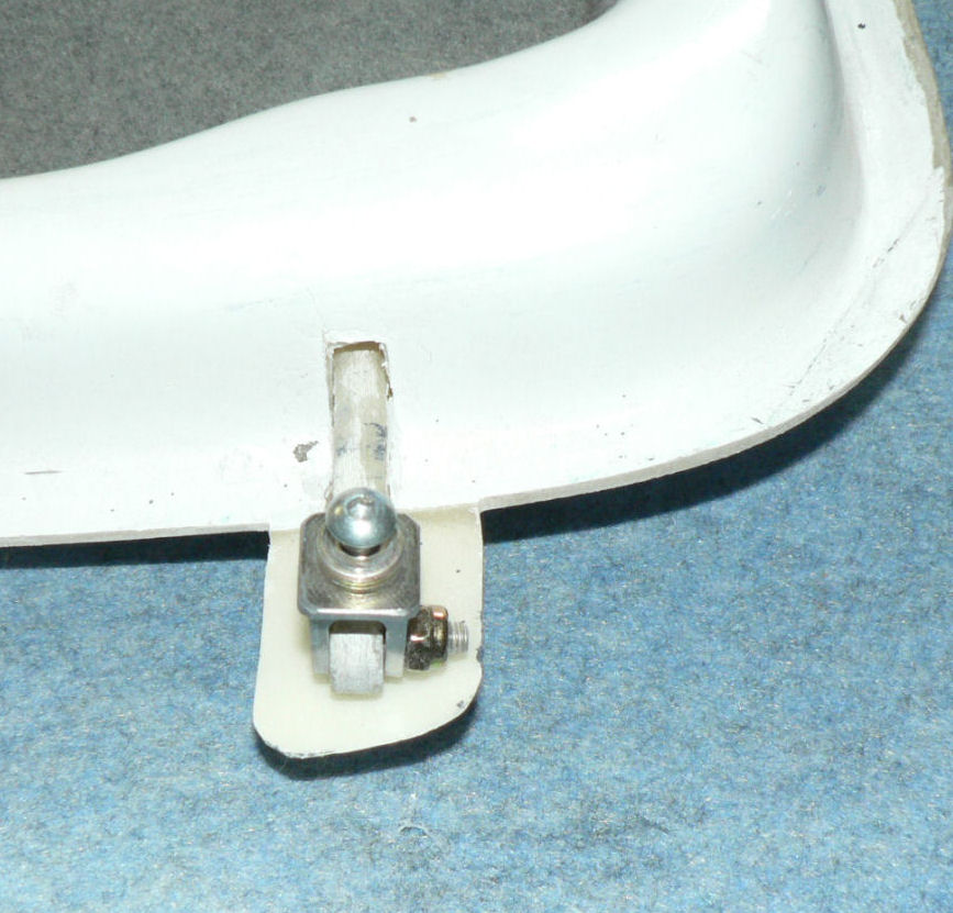
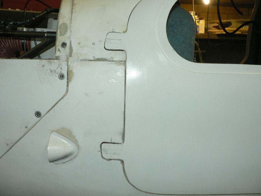
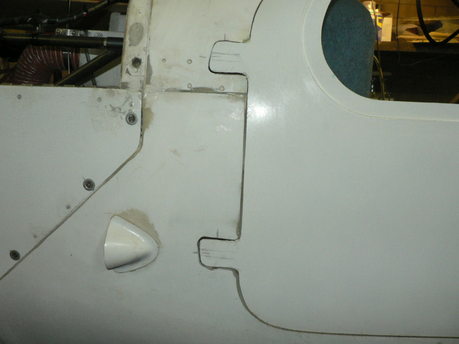
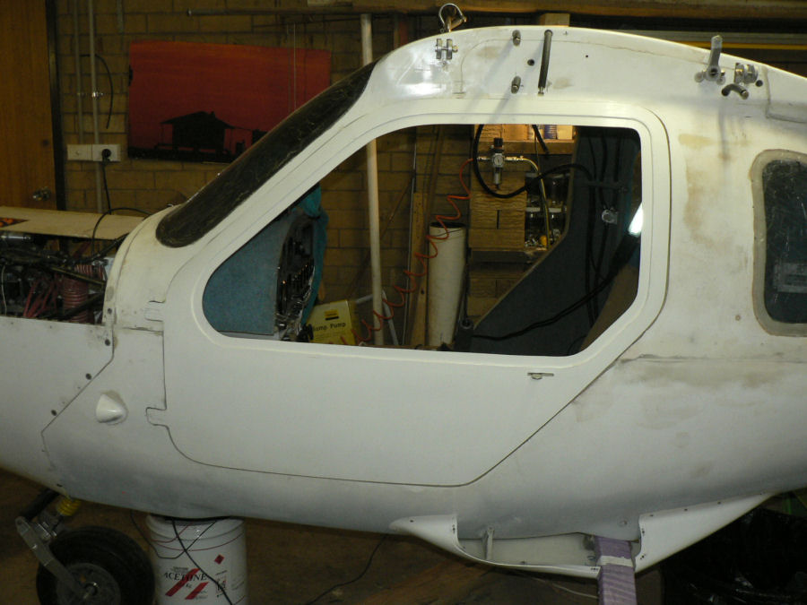
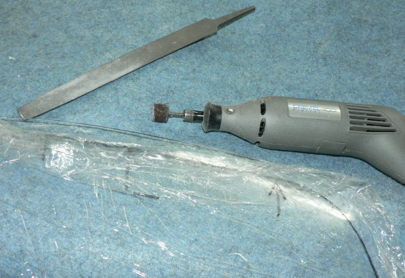
13-02-2008 Downloaded and printed most of the paper work required from the RAAust web site requred to get the A/C legally flying. Bought a 4 ring folder to store it in. Had a look at Warrens Sonex - he's working on the tailplane area - waiting on welding of the elevator mechanism. Jabiru J160 - Installed the door handle holders on both cabin doors. Cut the recess for the Jabiru hand holds using the Dremel tool and the drill like slitting tool - very effective shown in the pic against the rotary sandpaper tool. Cleaned up with the rotating sander in the Dremel tool. [ATTACH]4996.vB[/ATTACH][ATTACH]4992.vB[/ATTACH][ATTACH]4993.vB[/ATTACH][ATTACH]4994.vB[/ATTACH][ATTACH]4995.vB[/ATTACH] Prepared mating surfaces by removing gel coat and roughing up the glass side of the hand holds. Cleaned up parts with Acetone Mixed up Araldite and applied to mating areas. Insert hand holds into prepared recesses. Applied peel cloth & clamps to hand holds. Removed clamps & peel cloth after a couple of hours and removed excess araldite. Replaced spring clamps & peel cloth. [ATTACH]4997.vB[/ATTACH][ATTACH]4998.vB[/ATTACH][ATTACH]4999.vB[/ATTACH][ATTACH]5000.vB[/ATTACH][ATTACH]5001.vB[/ATTACH] Leave to cure. Removed the spring clamps at 22:45 now needs a bit of micro-ball filler to smooth it up a bit. Tomorrow will be soon enough. [ATTACH]5002.vB[/ATTACH][ATTACH]5003.vB[/ATTACH]

-
Electronics Project - audio mixer for headsets
Ross replied to sain's topic in Aircraft Building and Design Discussion
The early model radio supplied with my J160 kit has an input lead to which I have fitted a mono jack for external "music". So it mutes the external input when the radio is active. Presumably the upgraded versions still contain this feature. Regards -
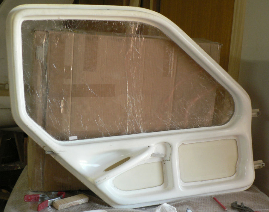
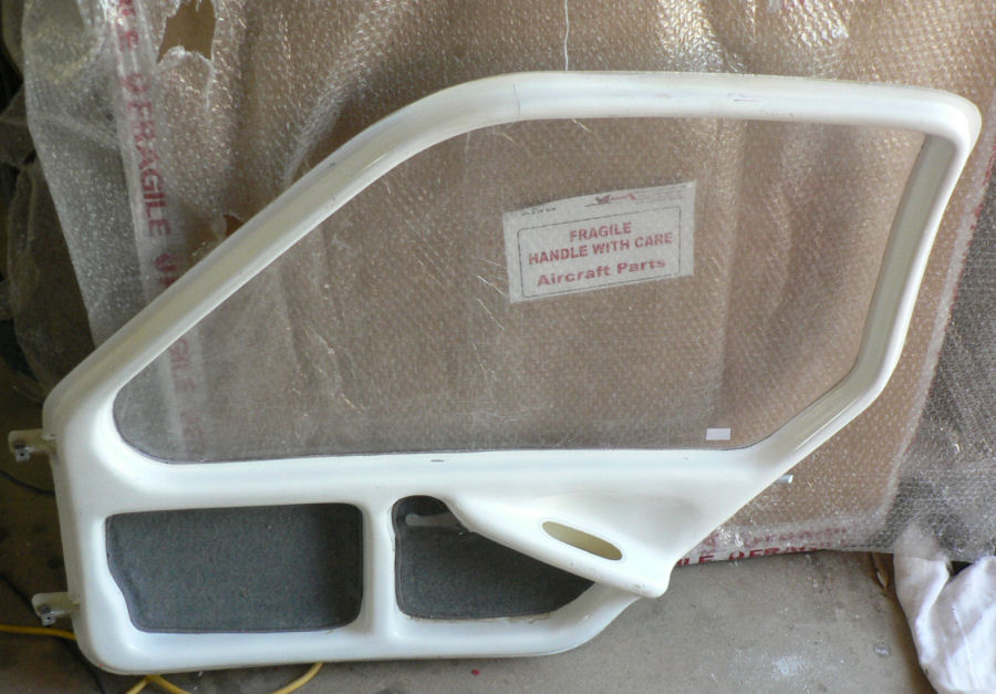
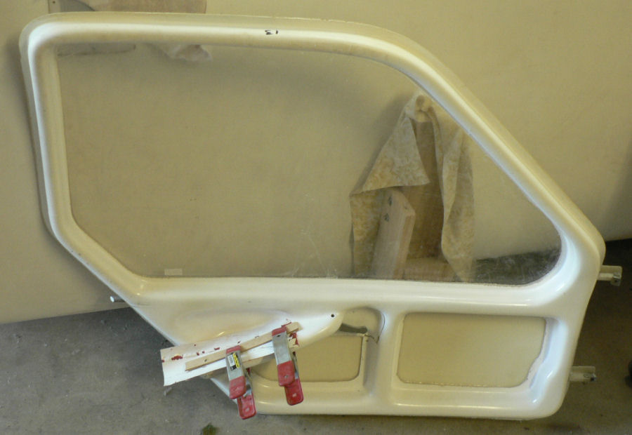
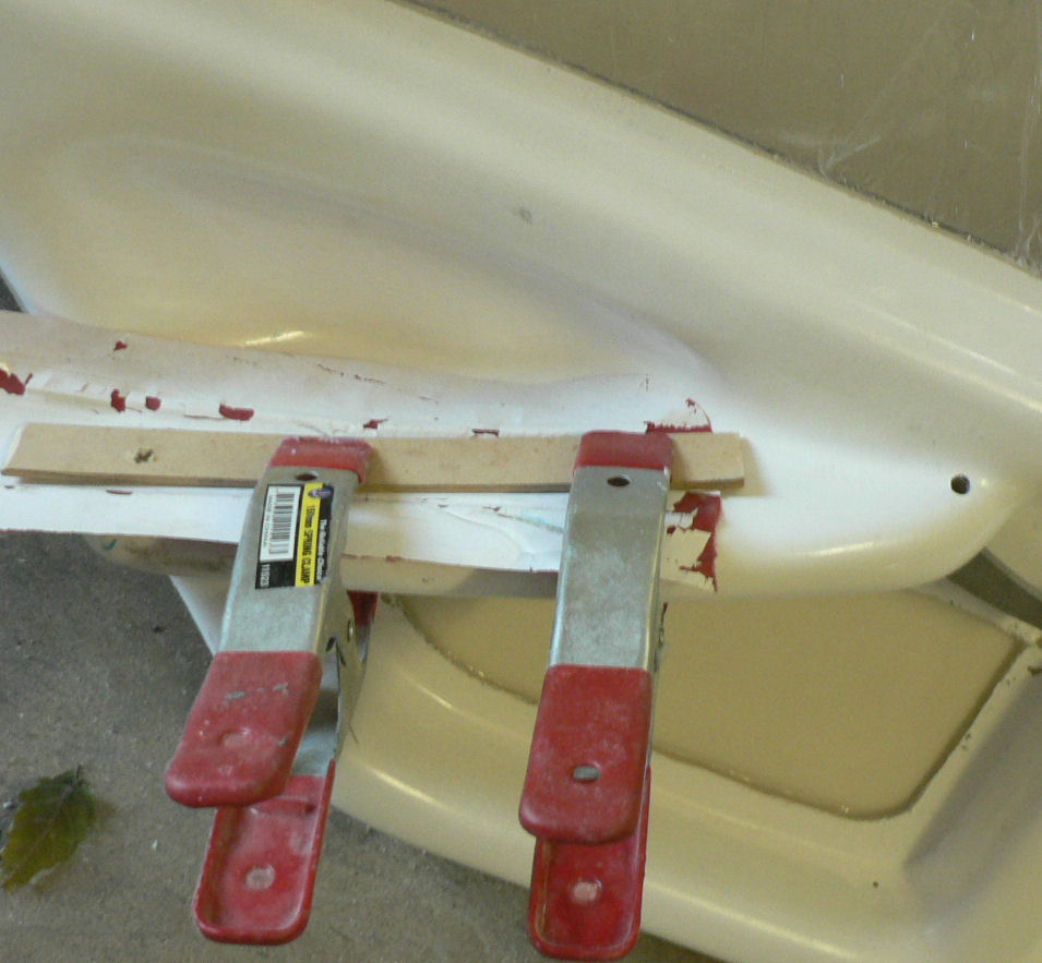
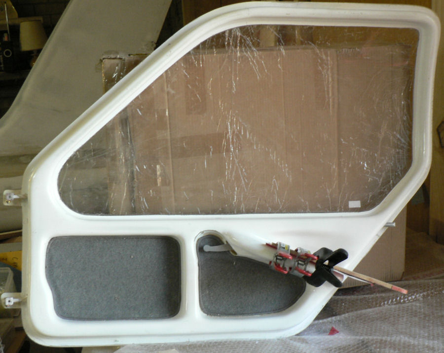
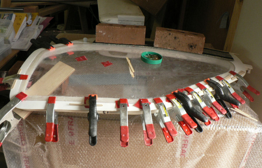
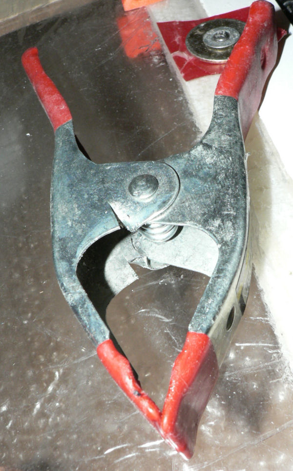
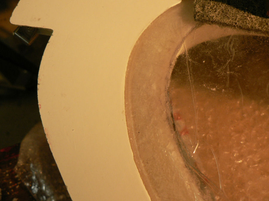
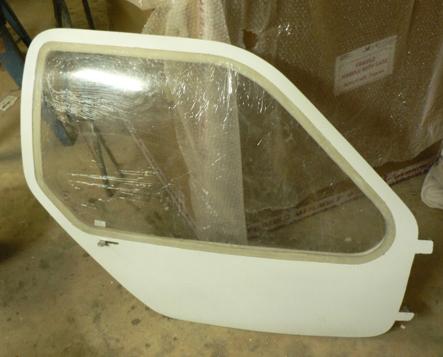
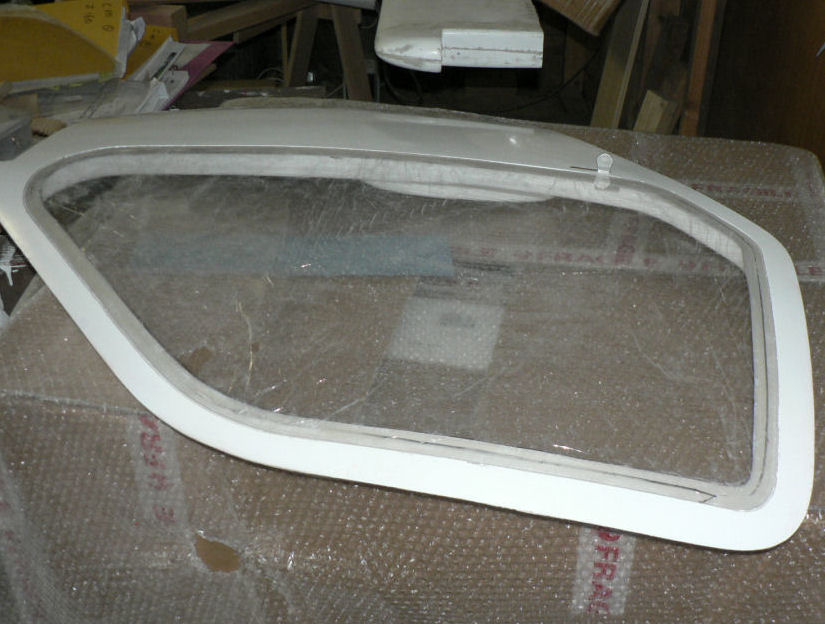
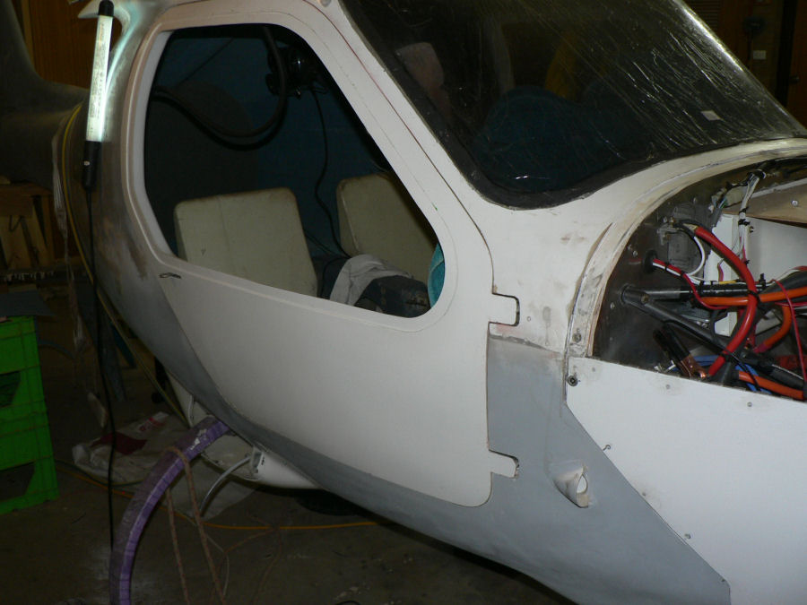
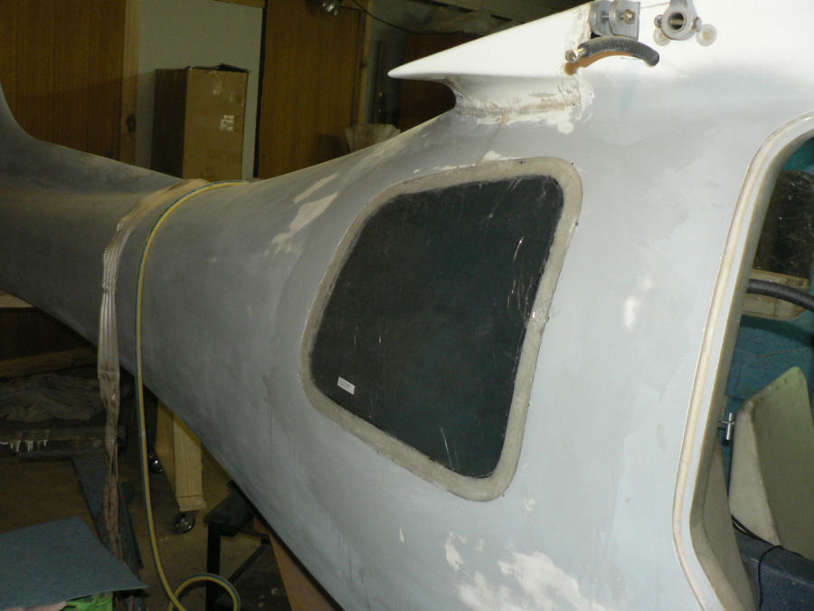
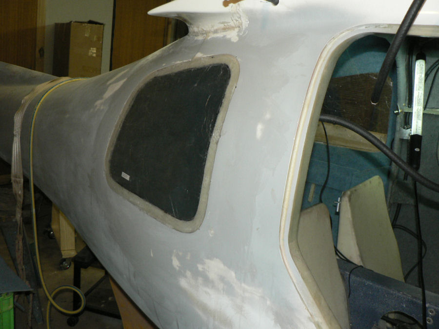
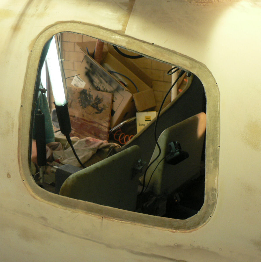
12-08-2008 Installing the Window in LH door Proceeded the same as for the RH door except that had a bit of trouble getting the window to seat in the recess so used some self tappers to pull it in a bit tighter as well as the clamps and weights. When the flock was applied then it started to rain - we had 8 mm - Yanco only 0.2 mm! [ATTACH]4980.vB[/ATTACH][ATTACH]4981.vB[/ATTACH][ATTACH]4982.vB[/ATTACH][ATTACH]4983.vB[/ATTACH][ATTACH]4990.vB[/ATTACH] Removed excess flock periodically cleaning up with acetone and adjusted clamps. Thought of a modification to the spring clamps to make them more secure when sitting on these slippery type round surfaces. Should have thought of it earlier. [ATTACH]4985.vB[/ATTACH][ATTACH]4984.vB[/ATTACH][ATTACH]4986.vB[/ATTACH] Despite the rain on and off during the afternoon the temp in the closed carport ranged from 25 degrees C at 11:15 hrs to 28.4 at 17:30 hrs.
-
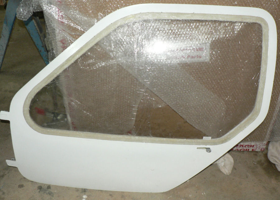
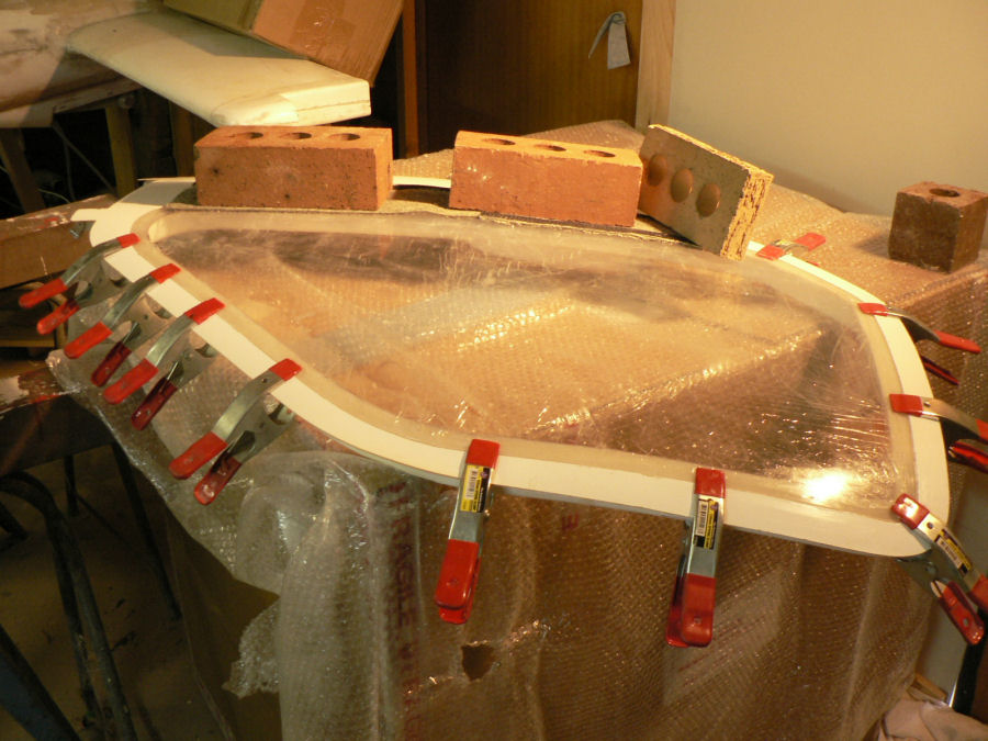
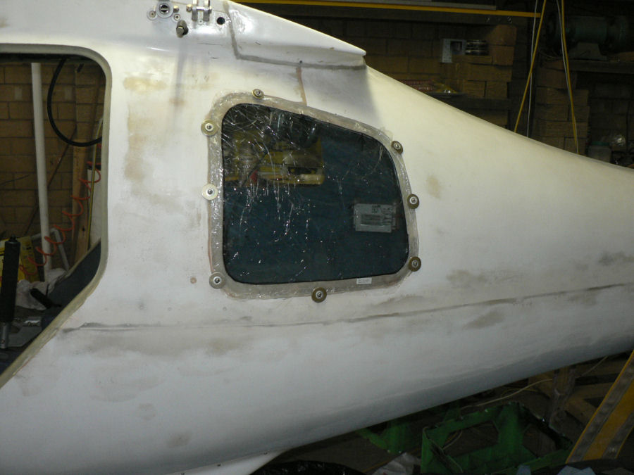
11-02-2008 Yesterday removed the doors again after partial curing and added another layer of flock in the hinge recess area and as the flock got firm reattached the doors adjusting the hinges to set the hinge skin & cabin skin. Today removed the doors again, removed the peel cloth and cleaned out excess flock from inside the holes for the hinge bolts. [ATTACH]4969.vB[/ATTACH][ATTACH]4970.vB[/ATTACH] Mixed a batch of epoxy for installation of the window in the RH door. It was double the size of batch used for the rear windows. (The mass of16 of 5/16" NC nuts on my old post office balance scales; 4 nuts of hardener, 12 nuts of resin) Painted the cleaned up area of the RH door with epoxy. Added flock to the epoxy & mixed to a fairly stiff mixture. Filled the door window matching groove with flock, a bit like a flat inverted V shape in the recess so that it would spread to the edges when the window was inserted. Inserted window clamped around the accessible sides and top and used weights on the bottom side. Continuously scraped off the extruded flock until the window settled. As it stabilised then wiped off with a rag soaked in acetone on the inside and the outside of the window. The protective covering of plastic had only been removed in the matching join area and about 5 mm wide on the outside of the window. The clamps and weights were removed at about 16:00 hrs which was 6 hours since the flock was mixed. Temperatures ran from 24 deg C to 28 degrees C. [ATTACH]4971.vB[/ATTACH][ATTACH]4972.vB[/ATTACH][ATTACH]4973.vB[/ATTACH] My wife came into the garage at 11:00 to tell me that we were going out to lunch and a bit later I discovered that I did not have enough 150 mm spring clamps - after chasing the four hardware shops in Leeton ended up with an extra four, the whole stock of one of the shops. We got to the pub at 12:29 a minute too spare!
-
10-02-2008 Decided to mount the hinges before setting the door windows as it will be easier to handle the doors without the windows being mounted. Cleaned up the hinge recesses with sandpaper then wiped them clear with acetone. Mixed an epoxy batch and treated the hinge recesses with epoxy on the bed area for the hinges. Added flock to the epoxy and mixed it making into a pretty stiff mixture. Applied a layer of wax to the underside of the bolt heads and the threads. Put the bolts into the holes with a washer then a layer of peel cloth under the head. Applied a layer of flock around and against the bolt thread on the hinge side of the hinge recess. Put a layer of peel cloth on the hinge end of the bolt. Wait until the flock is starting to feel firm under the outside peel cloth. Mount the doors in place in the door recess in the cabin with the hinges attached. Screwed the bolts from inside the cabin into the threaded base of the hinges until the door skins appeared flush with the cabin skin. [ATTACH]4962.vB[/ATTACH][ATTACH]4963.vB[/ATTACH][ATTACH]4964.vB[/ATTACH][ATTACH]4965.vB[/ATTACH][ATTACH]4966.vB[/ATTACH][ATTACH]4967.vB[/ATTACH][ATTACH]4968.vB[/ATTACH] Allowing it to cure now and check later for fit.
-
I endorse Peter's remarks as I remember similar comments from a nephew at Red Cliffs about his kit built J170 completed and flying in 2007. One extra point is also a better glide angle than the J160 giving a bit more range on an engine failure.
-
9-02-2008 Cleaned up gel coat from door window join area on RH door . Used Dremel with abrasive paper, hand held abrasive paper and paint scraper to get into the corners. The LH door had already been done but a bit more touch up was done on it as well. The RH door window was sat in the door join area and marked on the protective plastic cover on the inside of the window to show the extent of the join. Then the plastic protective cover was cut on this mark with a sharp knife. The top side was also marked and cut but not as wide as the joining side. Once the protective plastic was removed from the join area the window was roughed up with a piece of abrasive paper to make the epoxy, flock stick. The join areas of the door and window were both cleaned with air then acetone. They are now ready for epoxy and flock. [ATTACH]4957.vB[/ATTACH][ATTACH]4958.vB[/ATTACH][ATTACH]4959.vB[/ATTACH][ATTACH]4960.vB[/ATTACH] Also at YNAR today Flew Wally's J230 to Galore Hill & return on a strong closely spaced thermal day. Did a couple of landings first one was a long floater, the second was better. A Tumut Jab was visiting, We had a barbecue tea at the YNAR clubhouse. This was the second submission of this day's activities because I had done a preview without a submit and then exited thus loosing the work done. To then start again I first had to rename all the pics I had submitted today and trim them slightly to make them a different size then load them again and enter all the text again. After that I did a preview and am about to do a submit reply.
-
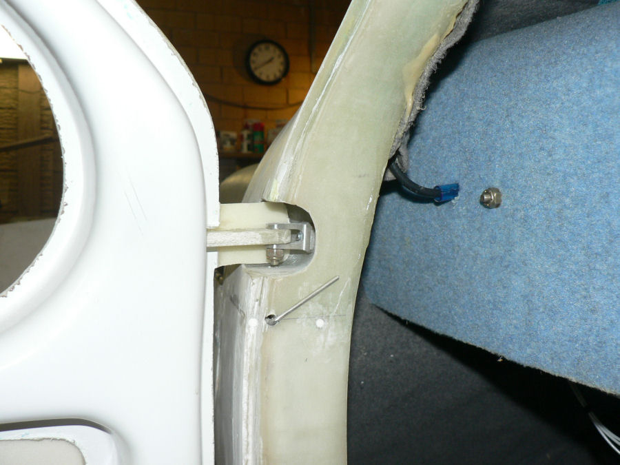
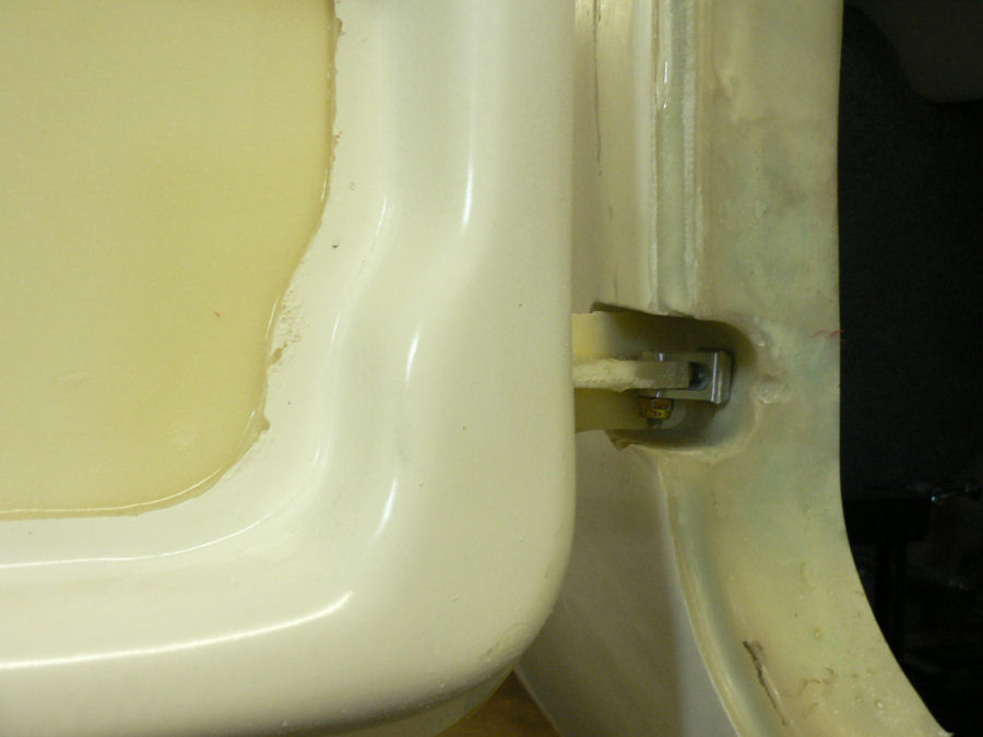
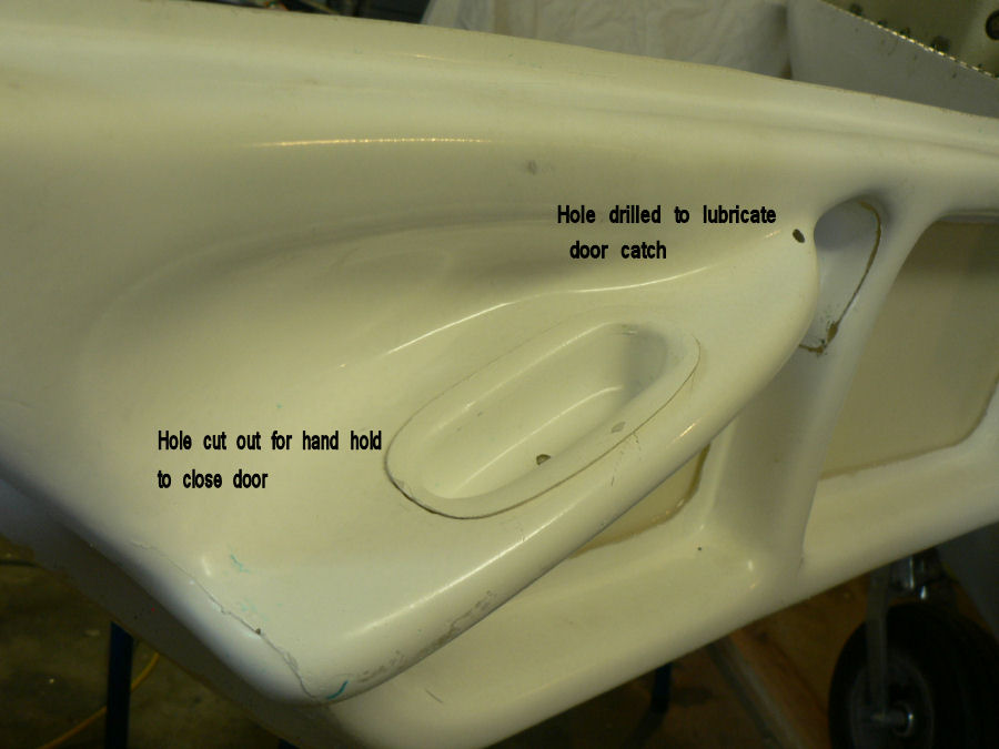
8-02-2008 LH Door Ground a bit more off LH door skin in hinge area. Drilled a hole for the door catch. Drilled a hole to get lubrication onto the sticking catch mechanism. Cut a hole for the hand hold pull. [ATTACH]4949.vB[/ATTACH][ATTACH]4950.vB[/ATTACH][ATTACH]4951.vB[/ATTACH][ATTACH]4952.vB[/ATTACH][ATTACH]4953.vB[/ATTACH] By the look of those hinge skins a bit more needs trimming off the skins so that they do not foul the glass in the hinge recess. [ATTACH]4954.vB[/ATTACH][ATTACH]4955.vB[/ATTACH][ATTACH]4956.vB[/ATTACH] Used Dremel with rotary emery paper to remove gel coat off the door window mating area & cleaned that up with hand held emery paper. RH Door Made up two hexagon bolts to suit the hinges replacing original pan head bplts. Checked fit of door. Slotted bottom hinge hole to get better fit of door. Both sets of door hinges will have to be packed up so that the door skins are level with the fuselage skin in the vicinity of the hinges. Will probably, as Jabiru suggests, pack between the hinge and the fuselage with some epoxy-flock with the door in place with slack hinge attachment screws and the door skin flush with the cabin skin. This will be done with wax on the screws to allow them to be removed. Allow this to cure then check the fit. Apologies. It was a Cessna.
-
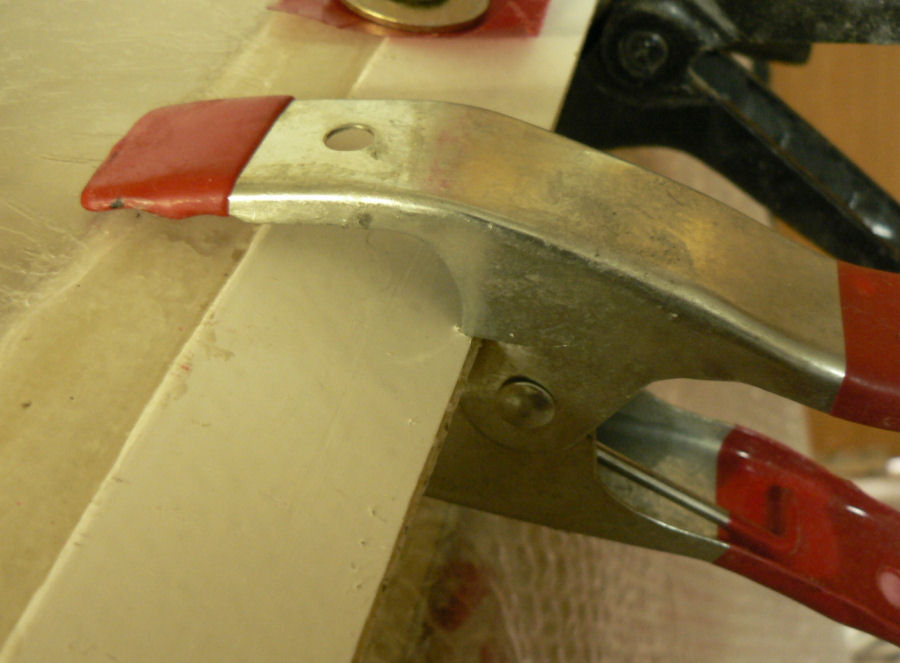
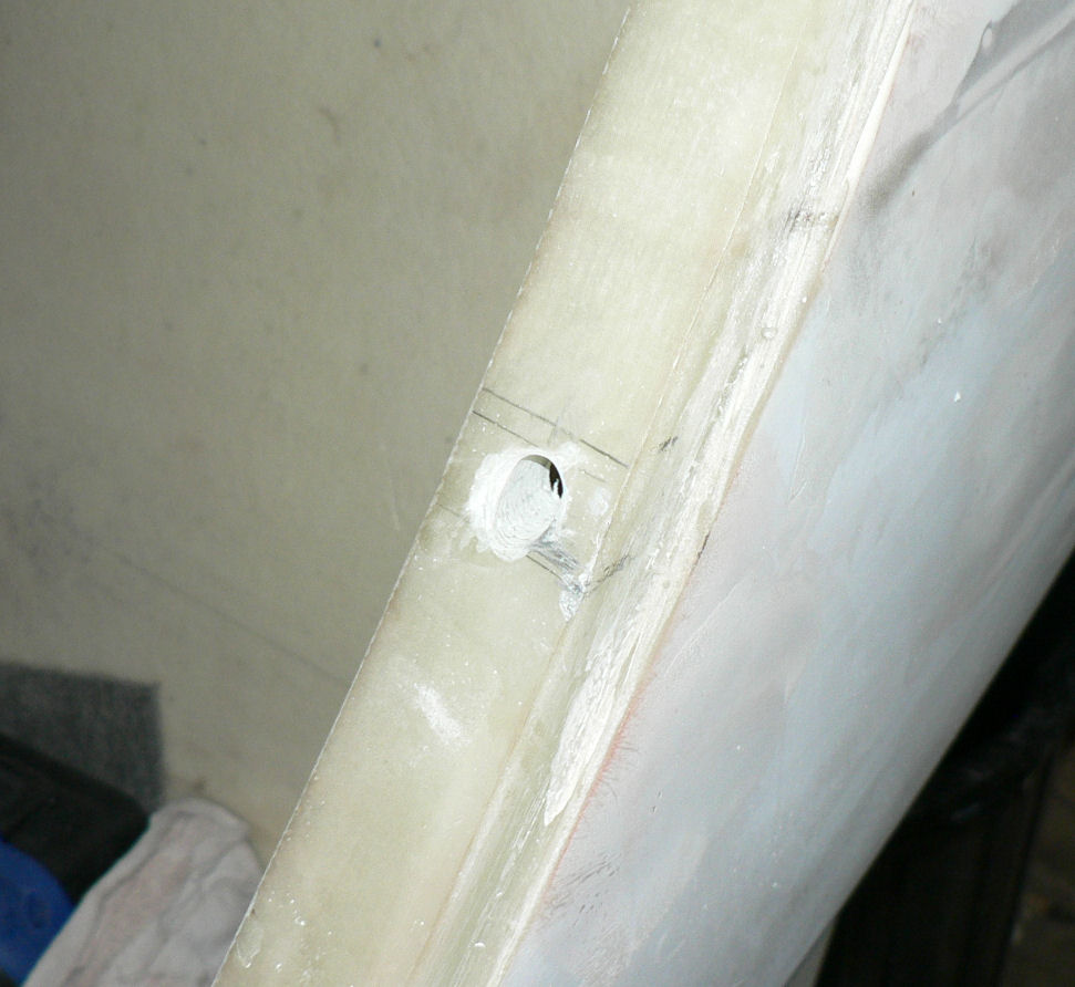
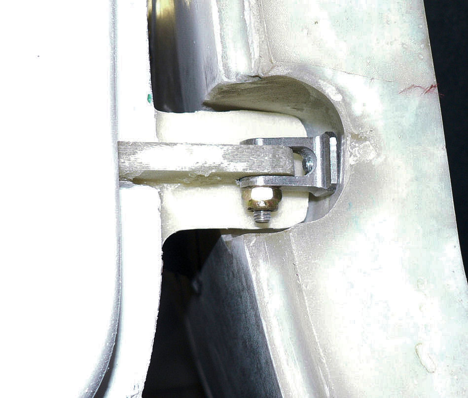
7-02-2008 Had a late start today. RH door has had hinges fitted earlier some months ago and door modified to fit opening. The hole for the door catch was also drilled at that stage. Today LH door hinges were mounted on the door and the original 3/16" BSW pan head bolts with a socket in the head were replaced with Hexagon headed 3/16" BSW bolts so that they can be handled with an ordinary small ratchet spanner with the instrument panel installed. See the pics taken of the RH door hinges with original bolts. There are only a few BSW bolts on the whole plane, quite a few metric and mostly AN series bolts on most of the flying controls, cable anchors and major structures like wings and struts. [ATTACH]4941.vB[/ATTACH][ATTACH]4942.vB[/ATTACH] Later kits use a different hinge and modified door that would allow better sealing at the leading edge of the door. See Captain's J230 @ YSWG kit thread for the later door hinge types. Marked out the hinge hole positions on the outside skin of the door then transferred them to the recess in the fuselage for the hinges and drilled a 13/64" hole for each hinge. Sat the door in the door recess with the hinges attached and the door catch retracted (it sticks anyway so far) and inserted the bolts from the cabin side and they both lined up - I could hardly believe it. [ATTACH]4943.vB[/ATTACH][ATTACH]4944.vB[/ATTACH][ATTACH]4945.vB[/ATTACH] The outside skin of the door over the protruding hinge attach point on the door had to be trimmed for both hinges and virtually no other trimming looks like being required. A little more trimming of the door skin around the hinges is still required. The trouble with this hinge design is that the skin moves forward as the door is opened so it needs excessive clearance.
-
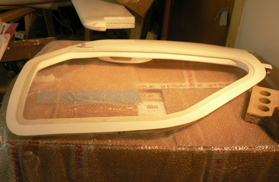
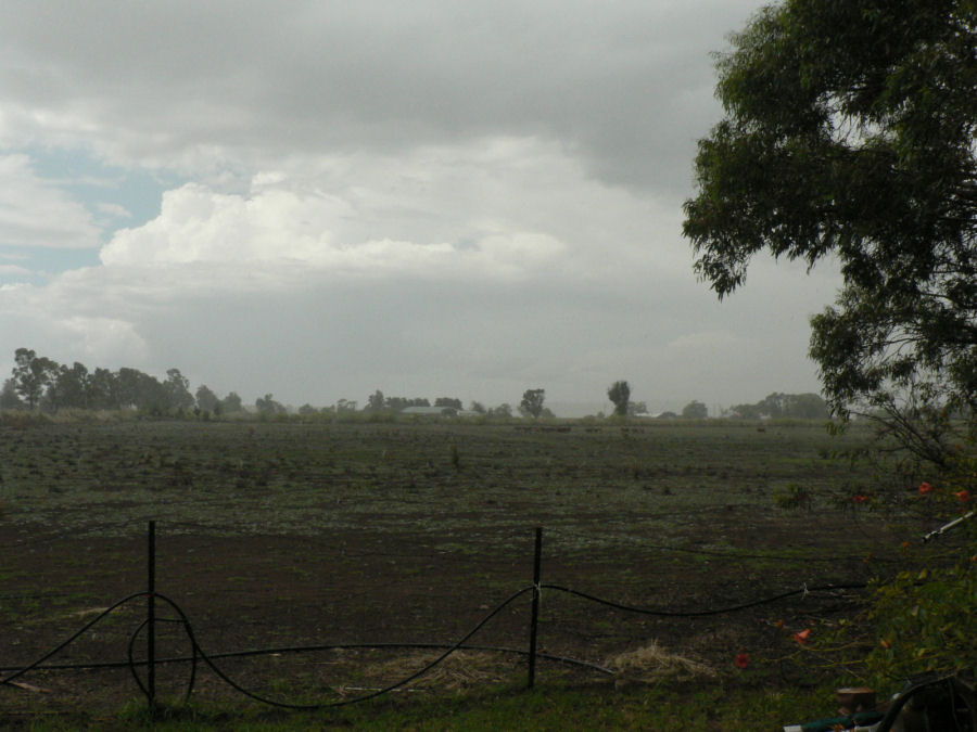
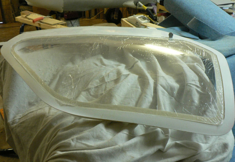
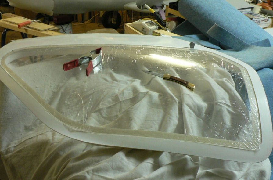
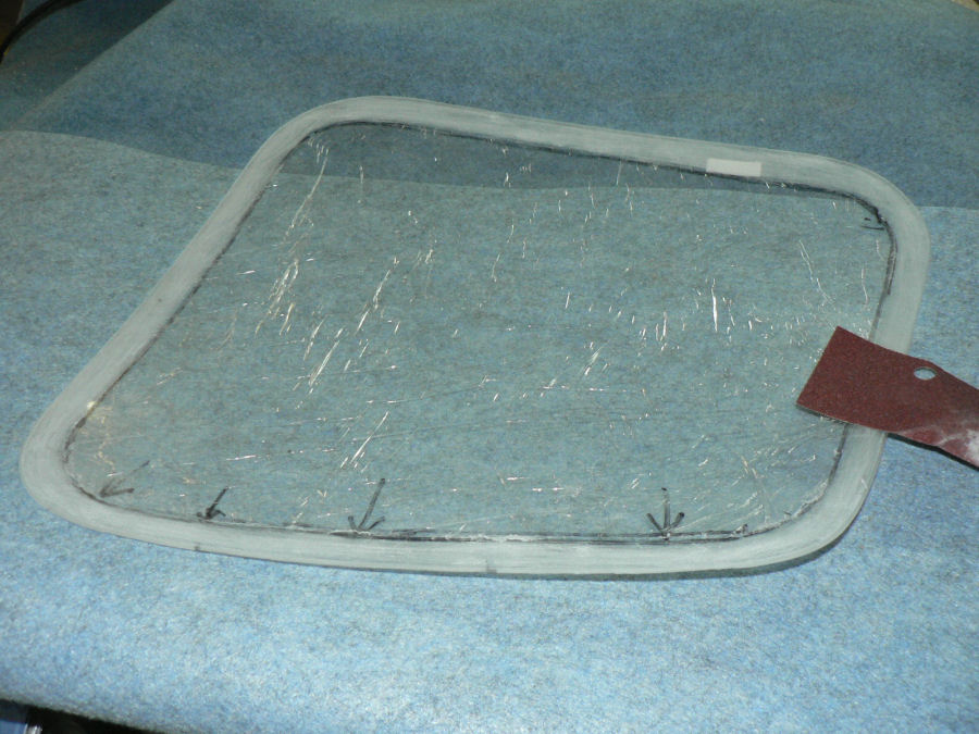
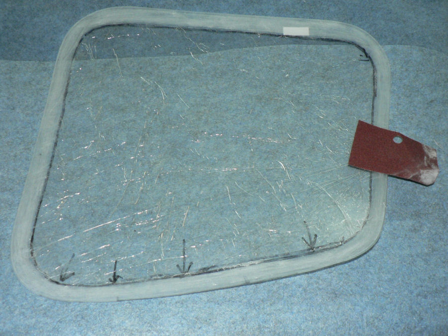
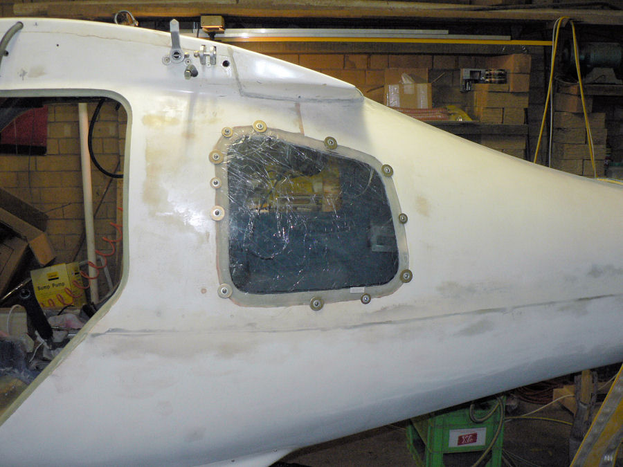
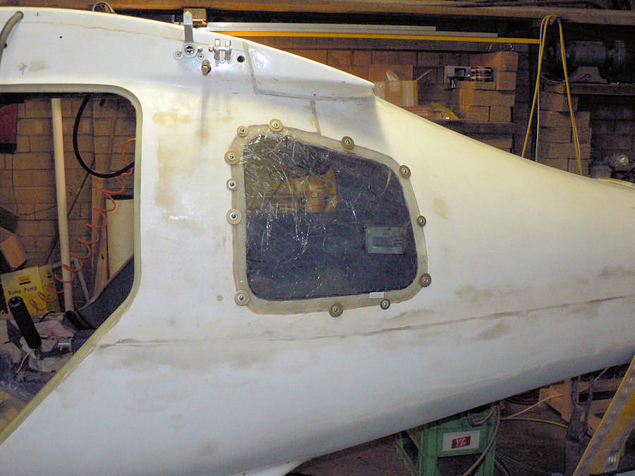
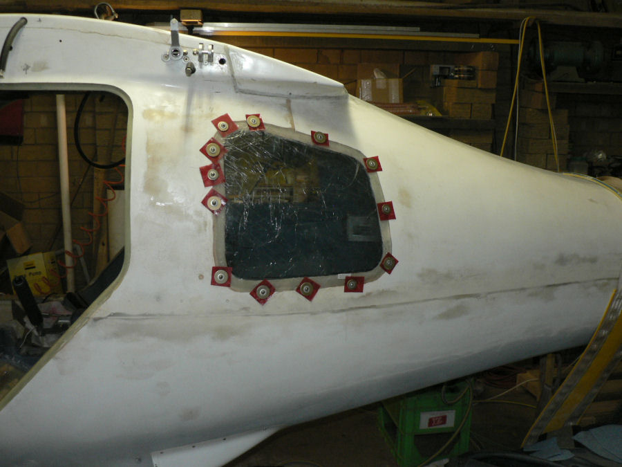
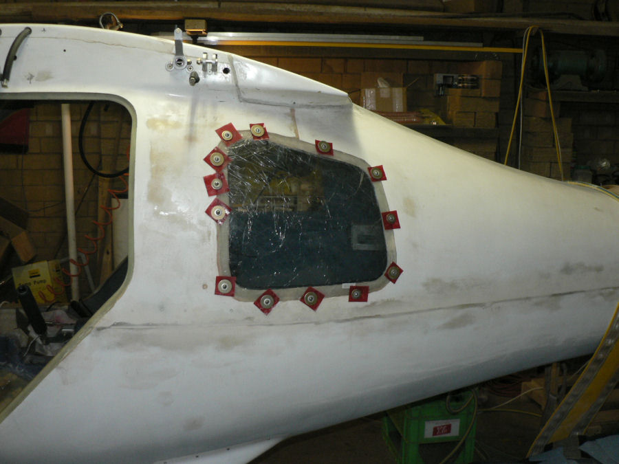
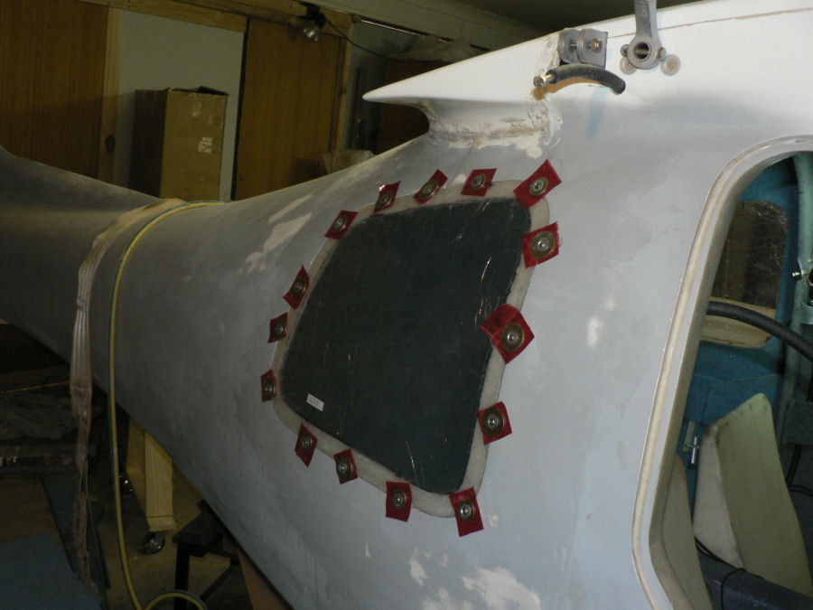
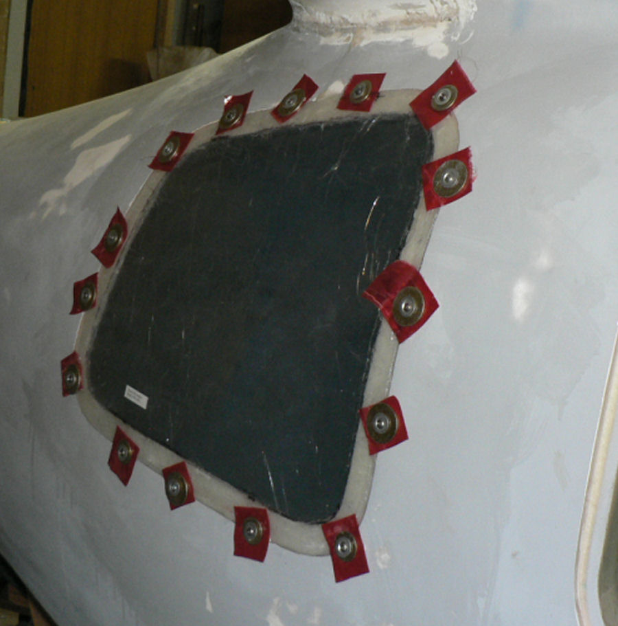
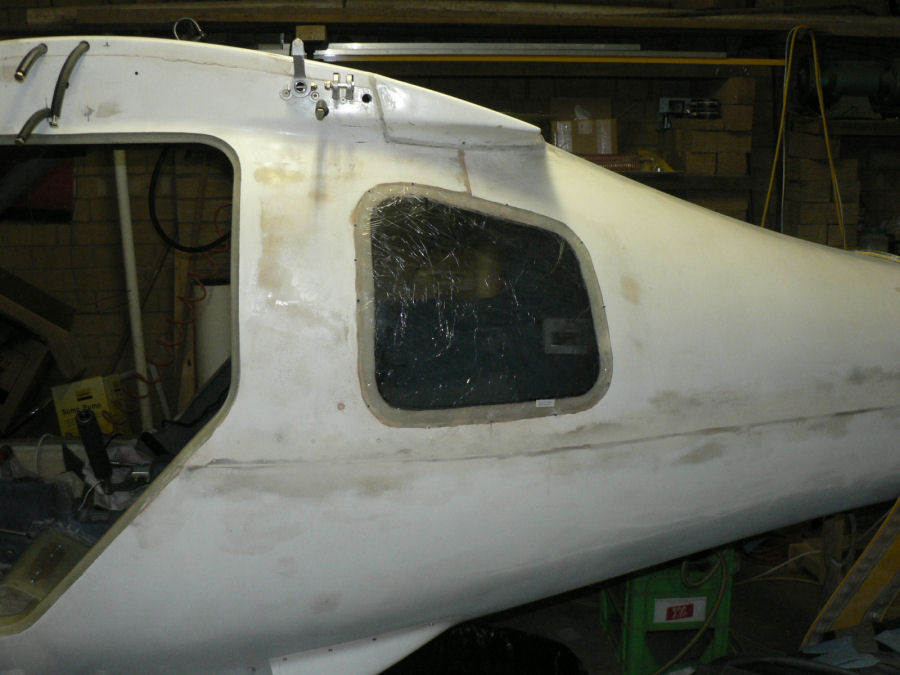
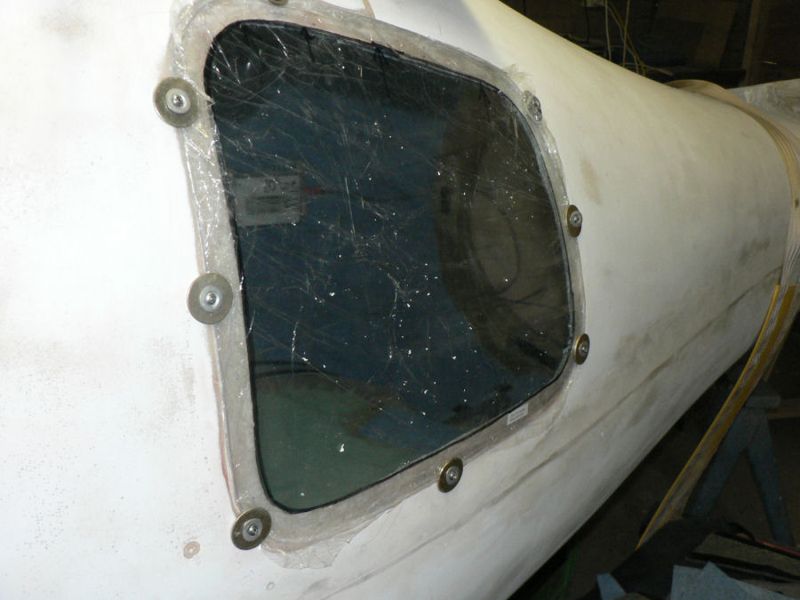
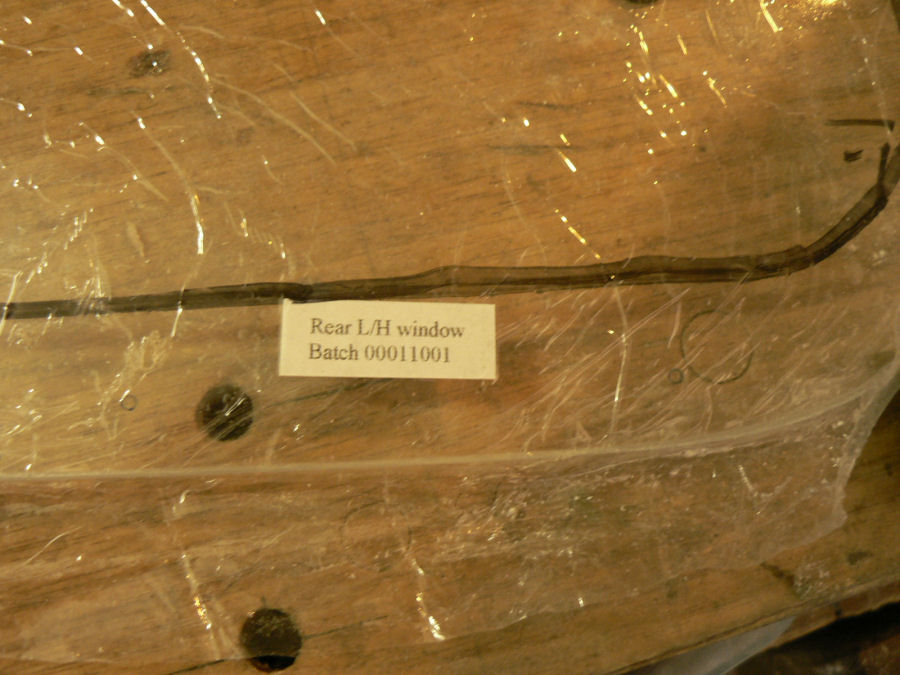
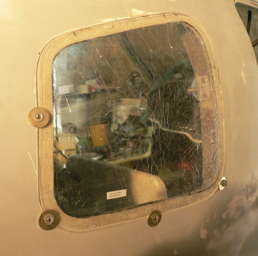
06-02-2008 Strange weather day here. We had a mild thunderstorm around midday with 6.5 mm rain at our place (far less at Yanco) followed by a dust storm in the late afternoon followed by another light shower of rain. Fitted both rear windows today partly interrupted by rain with increasing relative humidity. Started again when RH dropped about 10%. Sandpapered joining edge of both windows with 80 grit paper. Cleaned with cloth and acetone. [ATTACH]4912.vB[/ATTACH][ATTACH]4913.vB[/ATTACH][ATTACH]4914.vB[/ATTACH][ATTACH]4915.vB[/ATTACH] Mixed epoxy and applied a coat to mating surface on fuselage for windows which had already been sanded air blasted and cleaned with acetone. Mixed flock into epoxy and applied a layer to the mating area on the fuselage. Used self tappers with penny washers to hold windows in place and flush with fuselage. The excess flock was scraped off & cleaned up with acetone on the inside and outside of the window. Extra screws and penny washers were used depending on how the window was sitting in the mating slot with the flock in place. [ATTACH]4916.vB[/ATTACH][ATTACH]4917.vB[/ATTACH][ATTACH]4918.vB[/ATTACH][ATTACH]4919.vB[/ATTACH][ATTACH]4920.vB[/ATTACH][ATTACH]4921.vB[/ATTACH][ATTACH]4922.vB[/ATTACH] It finally worked out that putting peel cloth under the penny washers made the job much easier and tidier. Should have used it on the windscreen. It was taking around an hour to extract the screws, clean up the excess flock, clean the washers and screws and then replace them. Once the peel cloth was used, the screws only had to be removed once the flock was near cured. But I did turn the screws a few turns out then back in after about three hours for the second window otherwise they would be much harder to extract. It took about five hours from mixing the epoxy till the final screws were extracted for each window but it was two lots interrupted by the weather at midday. I was going to do them both together but the initial mix of epoxy was only sufficient for one window with barely enough for a sample to be kept.
-
How long would a Jab engine go for sitting on a conveyor not moving with the engine going flat out?
-
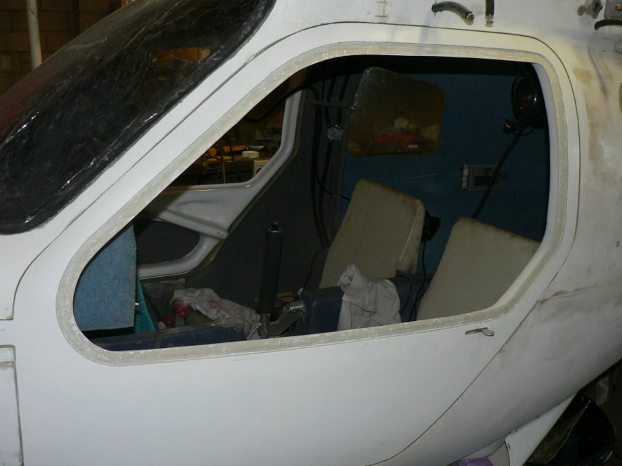
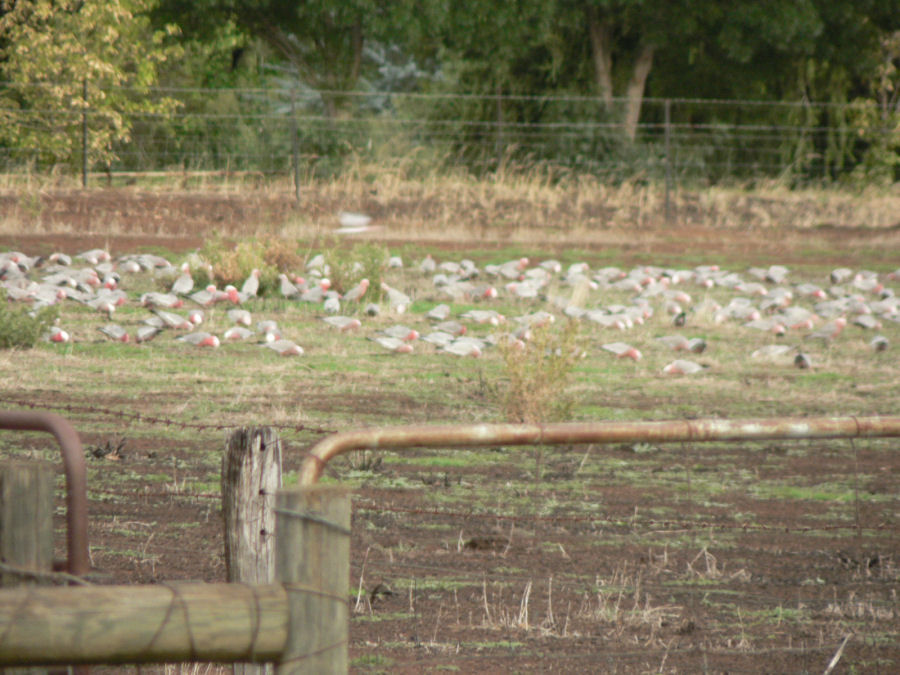
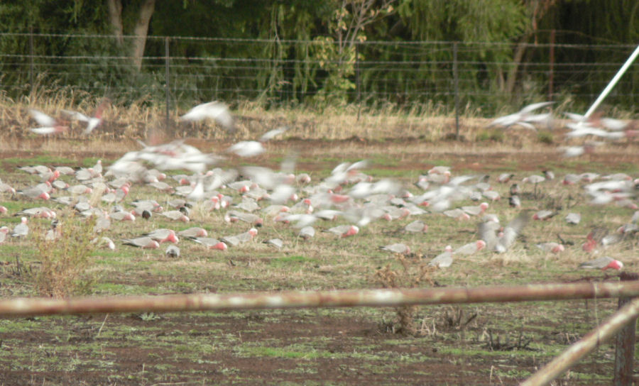
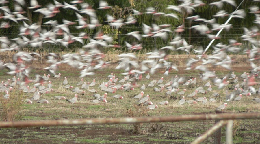
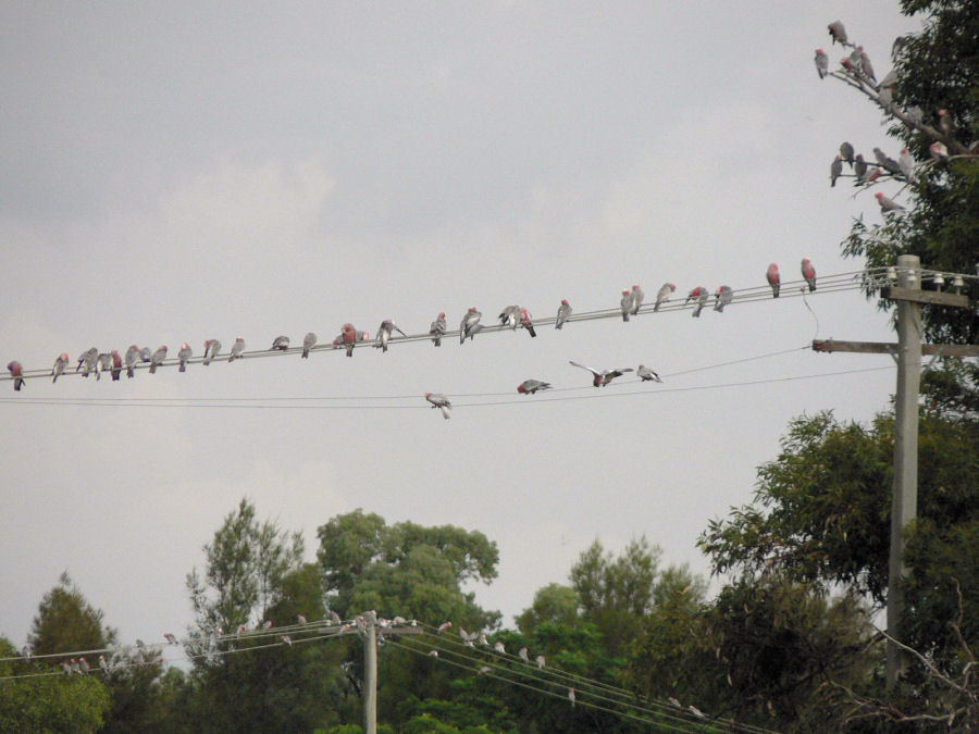
05-02-2008 Thanks for that Phil. I have saved the site. The load was a bit less than I thought, maybe 1 amp from memory but milliamps would be better! I have decided I want to fly it sometime soon so no more options for a while - just tidy it up and get it flying. Had to re-stick some of the velcroe strips in between the window work. Today prepared rear windows for installation. Used mains powered Dremel tool to clean up paint in window positions on fuselage. Can do it in minutes instead of hours with a piece of emery cloth. Drilled holes for temporary screws with penny washers to hold windows in place during curing of epoxy. [ATTACH]4901.vB[/ATTACH][ATTACH]4902.vB[/ATTACH][ATTACH]4903.vB[/ATTACH][ATTACH]4904.vB[/ATTACH][ATTACH]4905.vB[/ATTACH][ATTACH]4906.vB[/ATTACH] Try fit of windows & mark for area of window that will match the fuselage. Mark & trim windows to fit using Dremel tool. Trim off cling wrap plastic from joining areas on windows. This afternoon a very short duration very noisy thunderstorm went through here with one of the strikes probably less than 100 metres away - only 5 mm rain not like Sydney! After the storm a big mob of Galahs occupied part of our paddock for a while until another close lightening strike. Some very mediocre hand held telescopic pics follow taken in a hurry in fading light. [ATTACH]4907.vB[/ATTACH][ATTACH]4908.vB[/ATTACH][ATTACH]4909.vB[/ATTACH][ATTACH]4910.vB[/ATTACH]
-
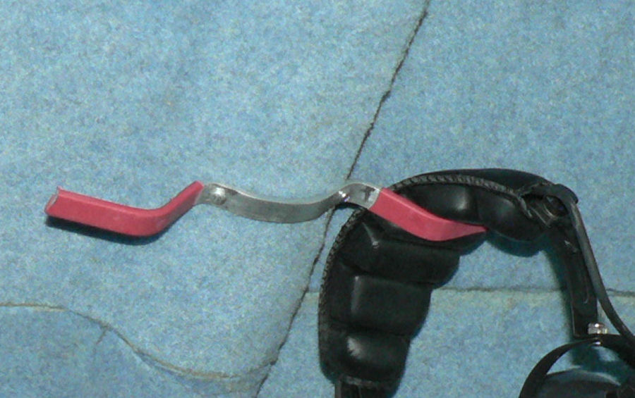
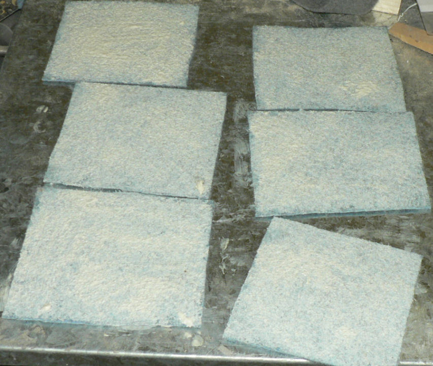
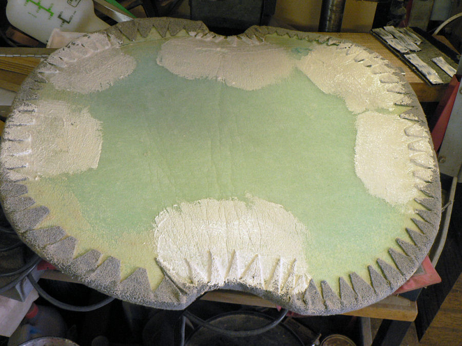
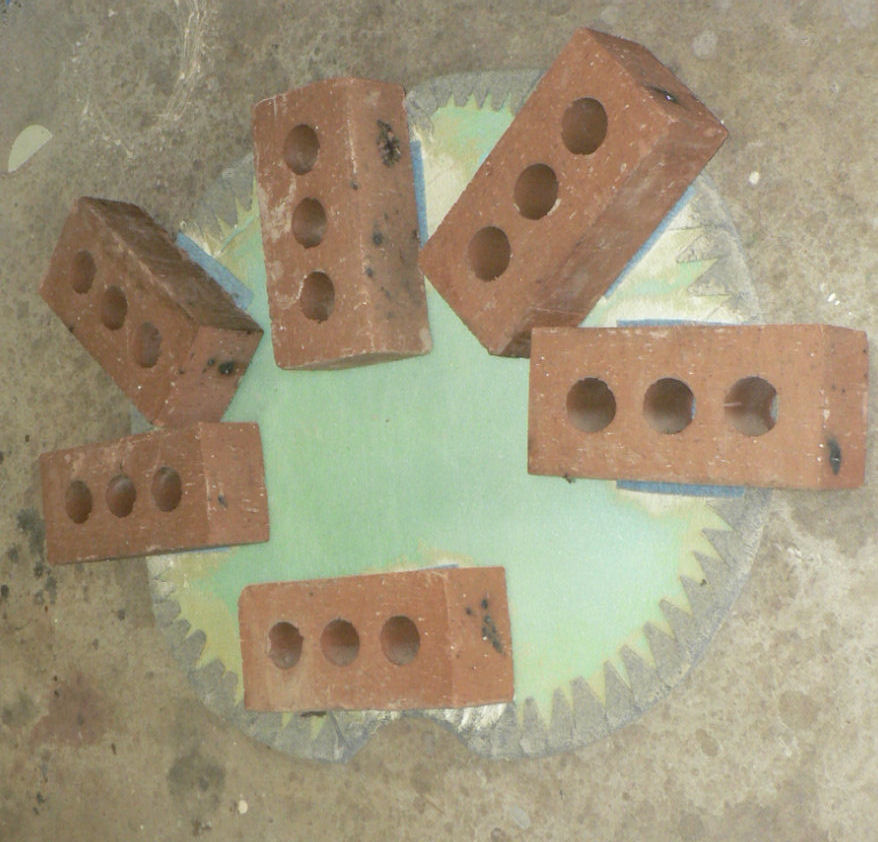
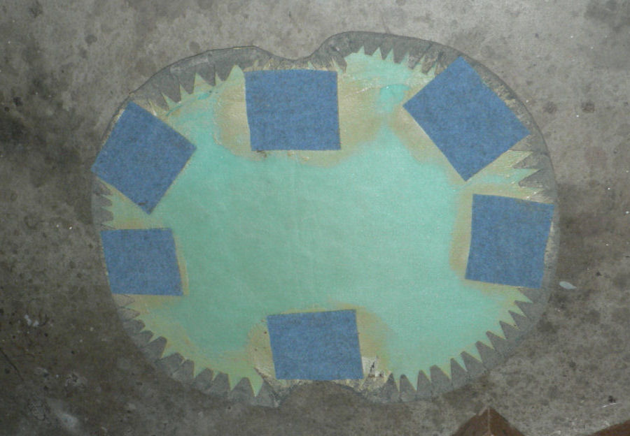
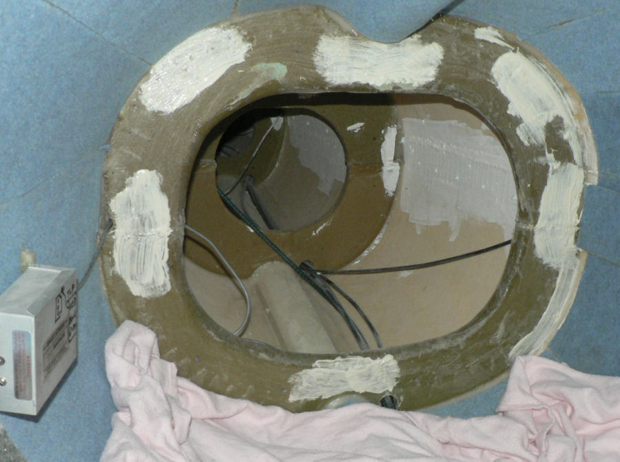
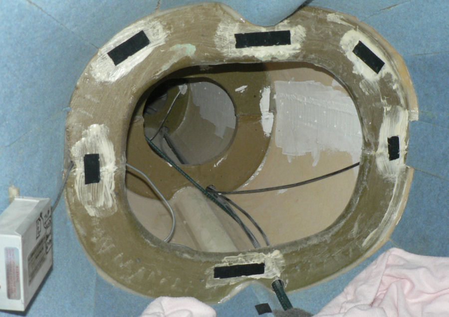
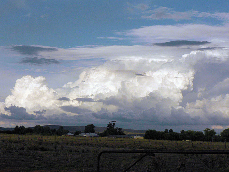
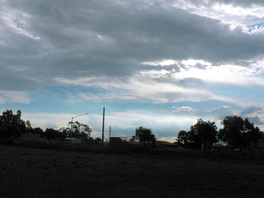
04-02-2008 Went to YNAR yesterday, the sky was pretty impressive so we did not fly. CASA was there testing the landing aids. Today took some pics of previous stuff but also attached the holder for the headsets. [ATTACH]4881.vB[/ATTACH][ATTACH]4882.vB[/ATTACH] Applied adhesive to the backside of six strips of felt. Applied adhesive to the backside of the sound curtain. When the adhesive was tacky applied the strips to the back side of the sound curtain. [ATTACH]4883.vB[/ATTACH][ATTACH]4884.vB[/ATTACH][ATTACH]4885.vB[/ATTACH][ATTACH]4886.vB[/ATTACH] Applied adhesive to the backside of six velcroe strips. Applied adhesive to matching positions on the circular whalebone at the rear of the luggage compartment. When the adhesive was tacky applied the six velcroe strips to the matching positions on the circular whalebone. [ATTACH]4887.vB[/ATTACH][ATTACH]4888.vB[/ATTACH] When the adhesive was cured positioned the sound curtain against the matching velcroe strips on the whale bone at the rear of the luggage compartment. [ATTACH]4889.vB[/ATTACH] At 18:45 hrs took a few pics of the clouds to the North East of us and one to the South West. Sunset about 120 hrs. [ATTACH]4890.vB[/ATTACH][ATTACH]4891.vB[/ATTACH][ATTACH]4892.vB[/ATTACH][ATTACH]4893.vB[/ATTACH][ATTACH]4894.vB[/ATTACH] They would have been pretty impressive over in Captain's backyard as well which is roughly South East of here.
-
I am assuming zero air velocity relative to the ground at the location of the attempted takeoff. The conditions at the start state that the conveyor moves at exactly the same speed as the aeroplane but in the opposite direction. So if the planes speed is measured in relation to the surface of the conveyor belt the conveyor will match it and the ground speed of the plane cannot get to take off speed relative to the ground because it will not move relative to the ground and therefore have no air speed. So it is an artificial constraint that the conveyor speed match the speed of the plane relative to the conveyor. If the plane speed is measured relative to the ground then the conveyor speed will match it and the wheels will be rotating fast enough to cope with double whatever the plane's air (ground) speed is and the plane could take off satisfying the condition that the plane speed and the conveyor speed are equal but in opposite directions.
-
02-02-2008 Prefit windscreen to fuselage. Sat w/s in place and drilled strategic holes around screen to help clamp it in place & hold it down flush with the fuse when epoxy is applied. [ATTACH]4868.vB[/ATTACH][ATTACH]4869.vB[/ATTACH] Marked top (outside) side of w/s protective material with a Texta pen in line with inner edge of where the epoxy will extend to when the w/s is fitted. Removed sticky protective material on inside of screen in line with the Texta marking. Removed sticky protective material from edge to about half way to the texta mark on the outside of the windscreen. Roughened the joining area on the inside of the windscreen with emery cloth. Roughened the joining area on the fuselage. Made a chamfer on the inside joining edge of the w/s and the matching area on the fuselage. Cleaned joining areas with air and acetone. Mixed a batch of epoxy. Applied epoxy to joining area of fuselage. Mix flock into epoxy. Insert a few screws so that w/s cannot move after being sat in place. Apply flock to joining area and insert self tapping screws with two washers to pull down w/s flush with fuselage surface. Apply extra screws as required. Wipe off excess flock with rag & acetone. [ATTACH]4870.vB[/ATTACH][ATTACH]4872.vB[/ATTACH][ATTACH]4871.vB[/ATTACH] Record time, temp and RH until cured or nearly so. Because there is some tension on the screws they will have to stay until the epoxy is cured but they can be rotated periodically so that they are not too difficult to remove. In fact I will remove and replace them one by one to wipe off excess flock underneath the washers before they are fully cured.
-
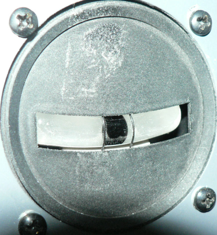
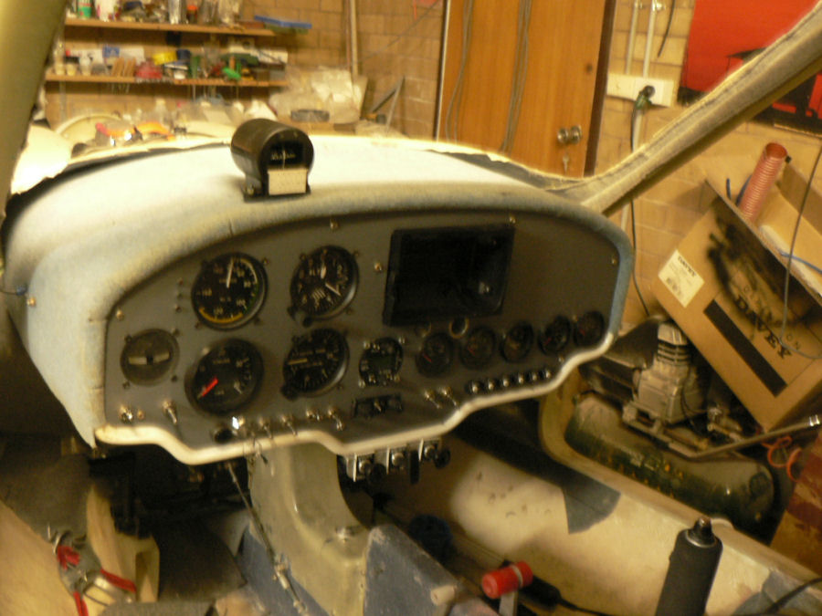
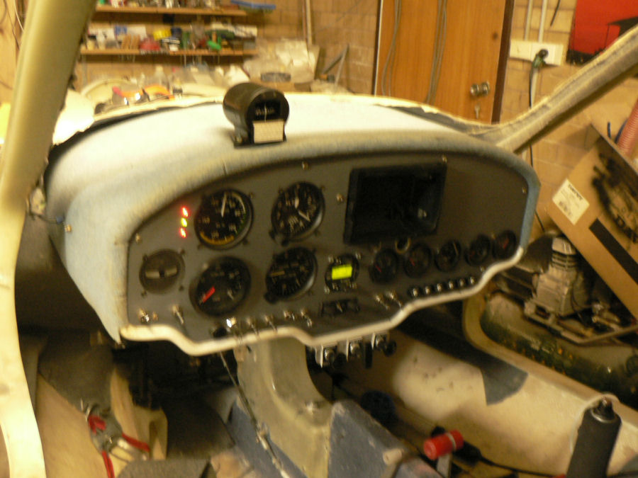
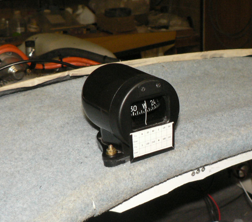
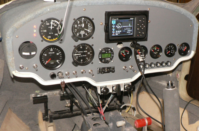
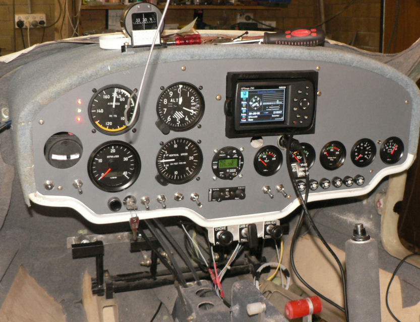
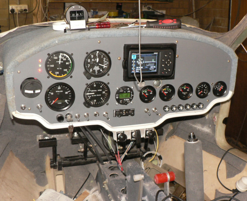
1-02-2008I thought I had written this up - it is in the log book but I had not put it in the forum. So I will add a pic after I have entered today's stuff (2-02-2008) where I have also done the pics already I hope. Hi Peter a correction. The lines look like thin black wires. They are fixed in place by a pair of narrow slits cut into the face of the instrument so they are not really adjustable. But pressing on the tube does move it and affect the position of the ball. So the only real correction is the position of the bolt holes in the instrument panel. My apologies. Magnetic compass mounted with 5/32" brass pan head bolts and face aligned parallel with the instrument panel. Loctite was applied to the bolts & nuts as I don't have nyloc nuts to suit. Compass was and can be rotated slightly to level it inside it's housing secured by a screw on the rear end of the housing. It is adjustable over about 5 degrees left & right in the roll axis. [ATTACH]4873.vB[/ATTACH][ATTACH]4874.vB[/ATTACH] (apologies for the two out of focus shots - negates the effort made to add them later from yesterdays pics) Some more cable ties used behind the panel to secure throttle cable, choke cable and excess antenna wire. Instrument Panel remounted.
-
What would you want to know first?
Ross replied to old man emu's topic in Aircraft Building and Design Discussion
Hi Ian Put me down for one please. But I am afraid I might have to start again. Regards -
What would you want to know first?
Ross replied to old man emu's topic in Aircraft Building and Design Discussion
My problems were similar. Mixing resin & hardener was my initial problem and the speed and nature of curing. Some experiences during my build which is not passed by a LAME yet. Purchased an old set of post office letter scales w/o weights maybe about 1 Kg or 2 lbs limit capacity for weighing out resin and hardner. Bought 48 of 5/16" shiny nuts to use as units of mass for the balance. 3 nuts of resin and one nut of hardner by mass. (3 to 1, or 6 to 2, or 9 to 3, or 12 to 4 etc) Using nuts any larger than 5/16" as units of mass would result in too much loss of epoxy when doing the many small jobs that are involved like attaching three alileron hinges or attacjing the control stick limit. Bought extra mixing containers 100 at a time like the Jabiru supplied ones from the local wholesale shop Bought boxes of medicine measuring containers from a local chemist - they come in packets of 50. Bought paddle pop sticks (craft sticks) from the wholesale shop. Bought a combination electronic temp, relative humidity. and clock instrument to record those parameters until jobs are cured. I generally recorded parameters hourly up till midnight trying to make sure that application of epoxy and assembly was completed by about 16:00 hrs. It also recorded min and max. So far I have mixed about 130 separate batches of epoxy or epoxy & flock or epoxy and microballs and a sample of each batch has been taken and allowed to cure in the medicine glass. Once cured it is numbered with permanent texta and stored in a "Honey" jar with other samples which are also labelled with the number and description of where they were used. This is also recorded in the constuctors log book. Bought bulk acetone in 20 litre containers (on my third 20 litre container) Bought a paint scraper with a carbide blade a bit like an enlarged version of a single blade shaving razor. My experience of curing is only in the assembly of a Jabiru kit is that it proceeds at any temp above about 16 degrees C but more slowly as the temp drops closer to 16. At 16 C it would probably be more than 12 hours maybe 24 before the job was safe to support itself. Twenty five degrees C is pretty good for the type of epoxy jobs on assembling a Jabiru Kit giving time to do a number of mixes and assemblies before it cures. Large batches will get very hot and will accelerate the curing making it difficult to complete before the mix becomes unuseable. High temperatures like 30 degrees C plus speed up the curing and are good after the initial assembly of parts and application of epoxy. Interrupted curing by low temperatures will continue once the temperature rises again. I really noticed it this summer after a cold winter that the partly constructed J160 gave off quite strong fumes once we had a few very hot days which has since virtually stopped except for new work. My garage has had a few days over 40 degrees C which is pretty good for developing full strength curing but it needs the time to do so. I purchased a paint stripping gun which I found very effective for adjusting or stress relieving after curing especially of items like hinges. The paint stripper gun (hot air gun) is also very useful for disassembling parts that need to be moved or modified. The curing process is a chemical reaction that depends on the mixing of the correct ratio of the components ie resin and hardner. Mixing the components not in the correct ratio will result in an unpredictably lower strength of material. -
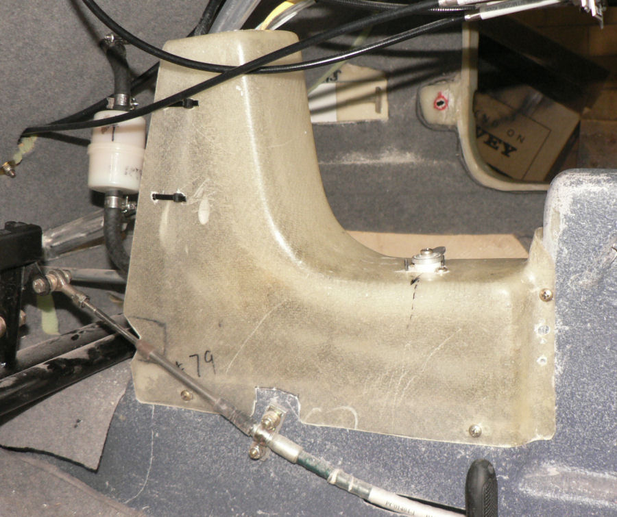
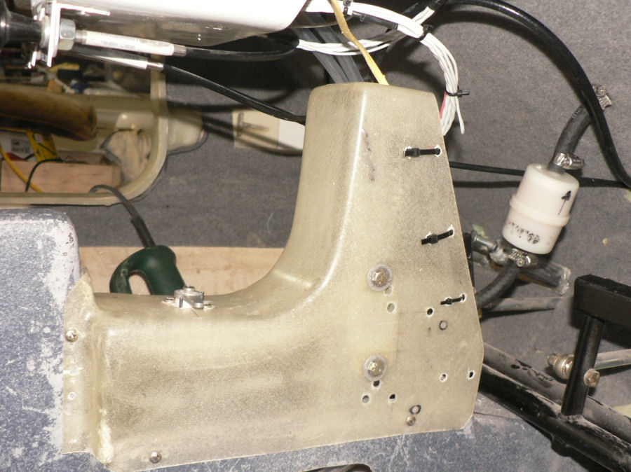
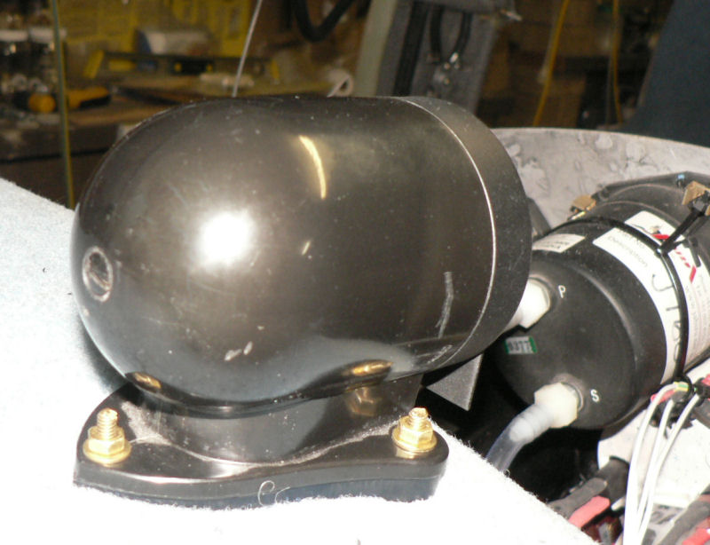
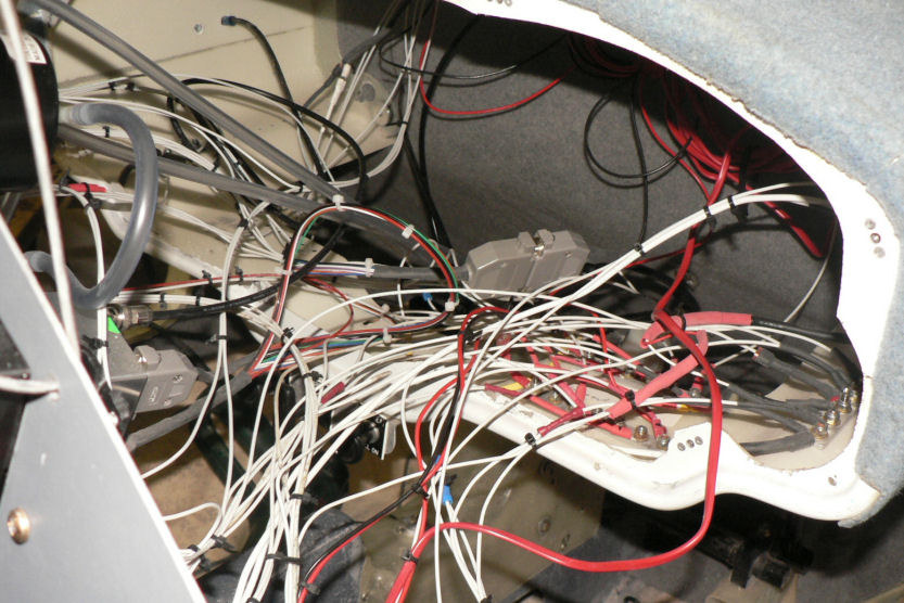
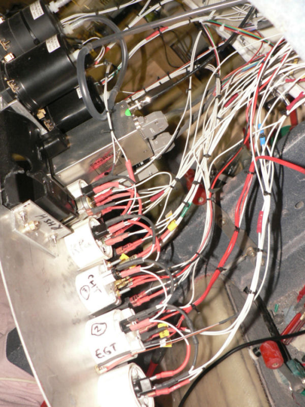
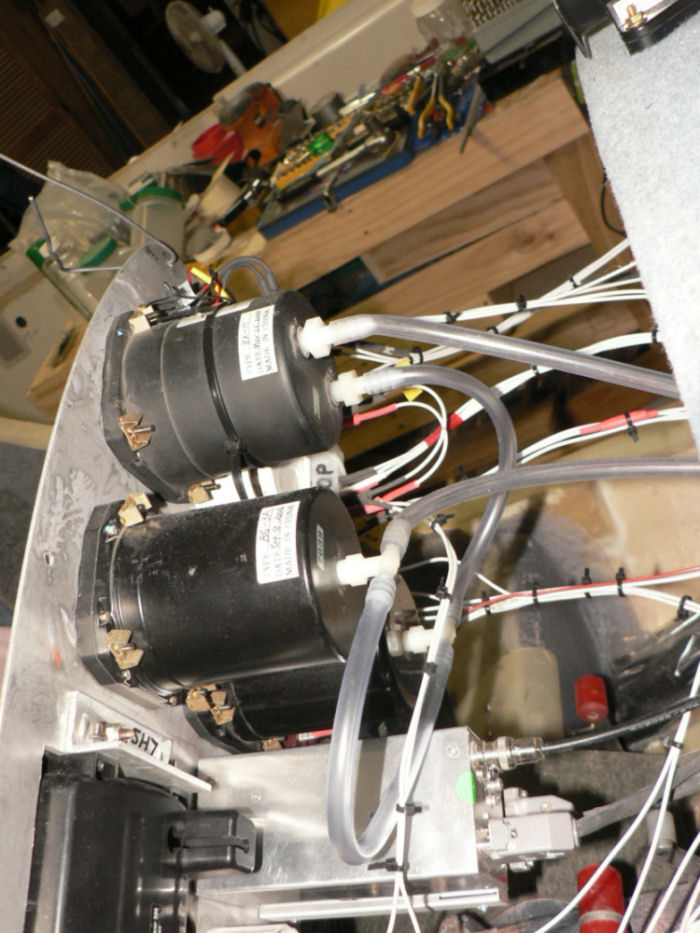
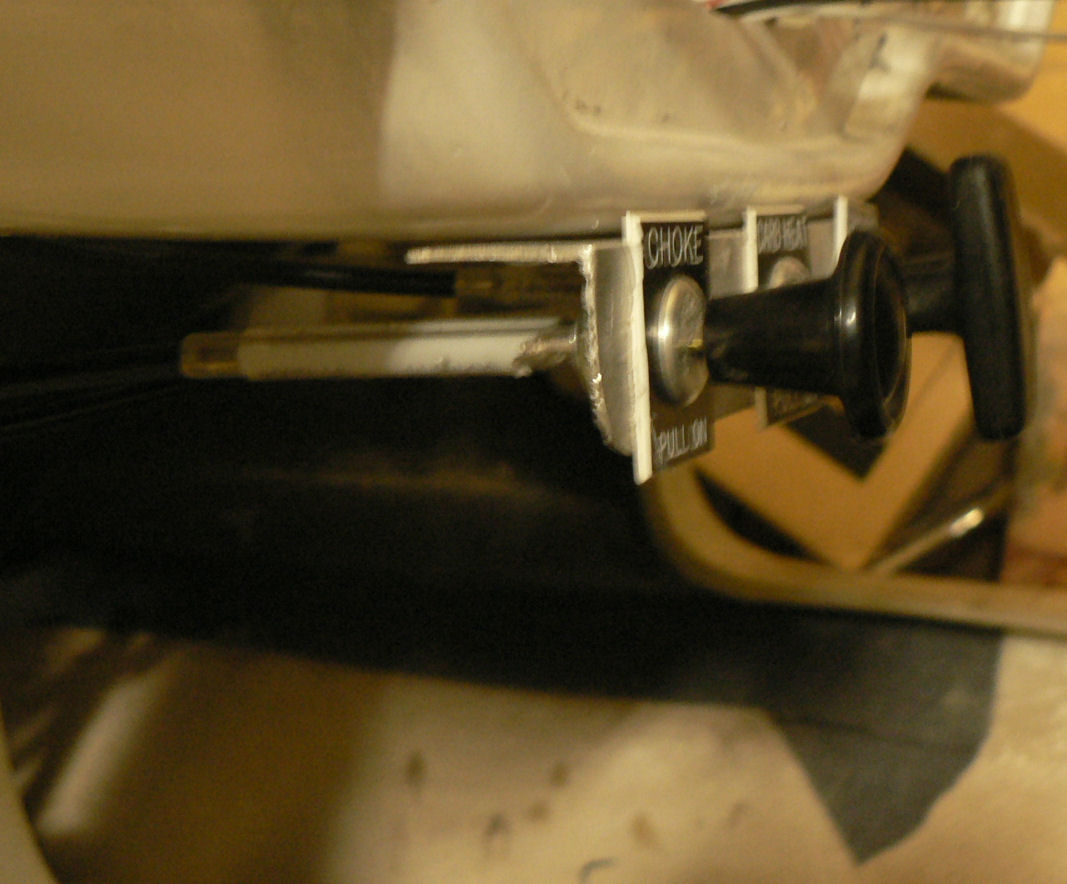
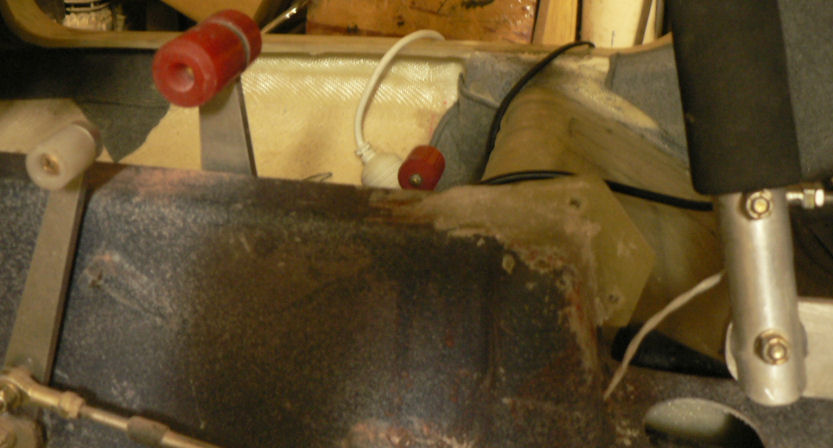
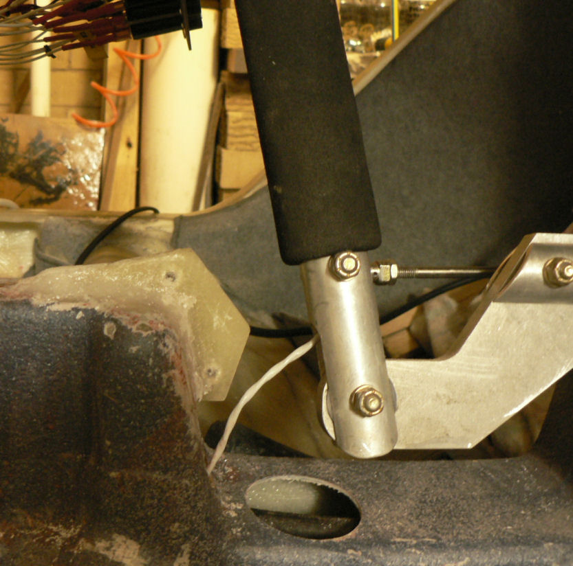
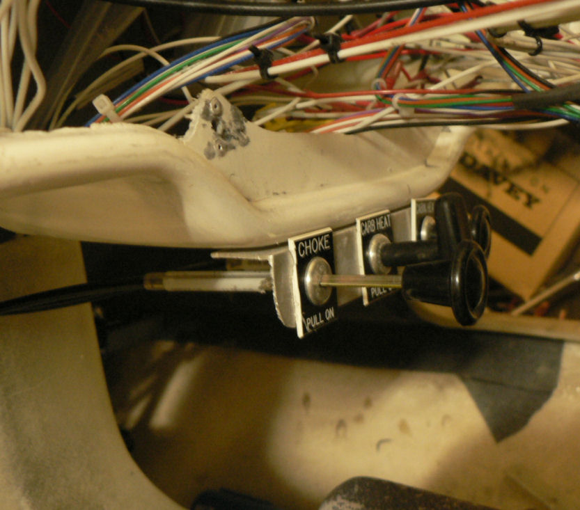
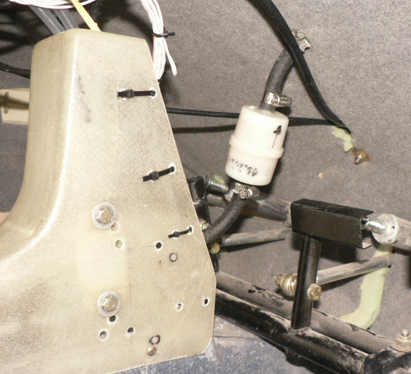
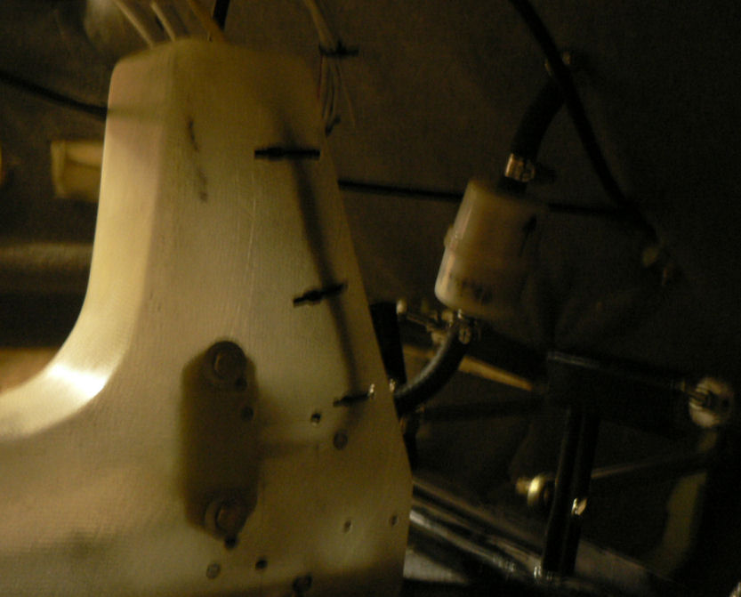
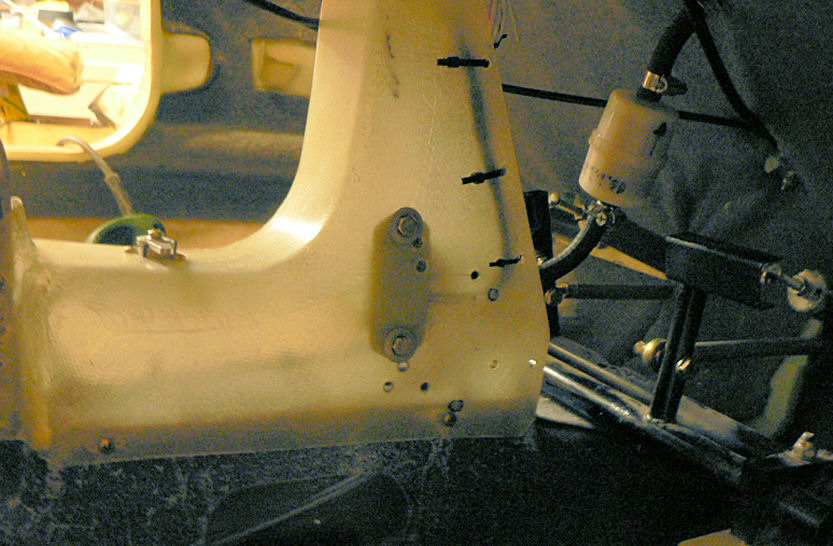
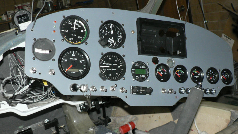
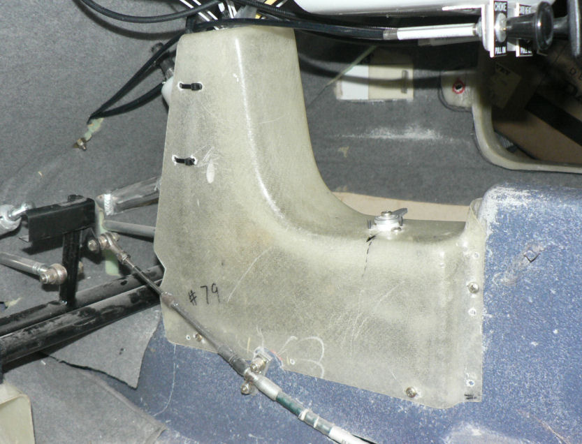
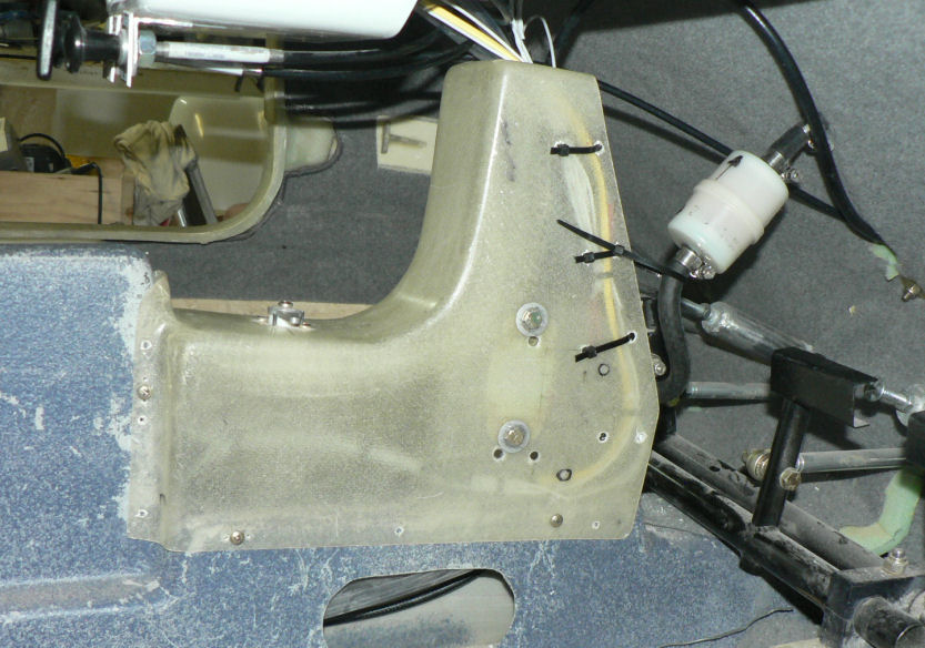
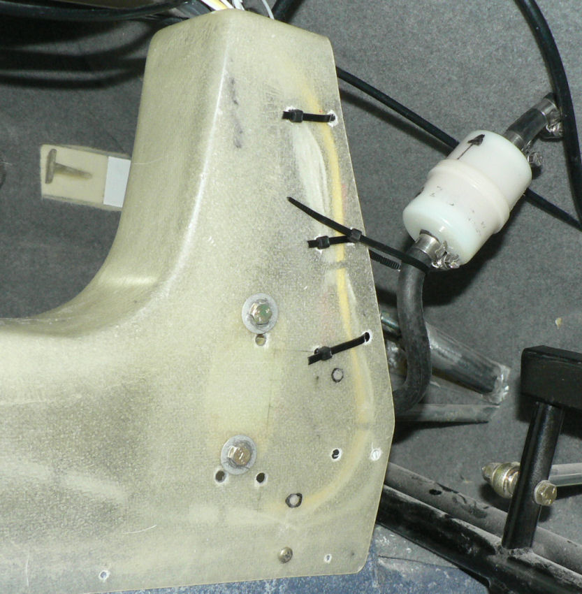
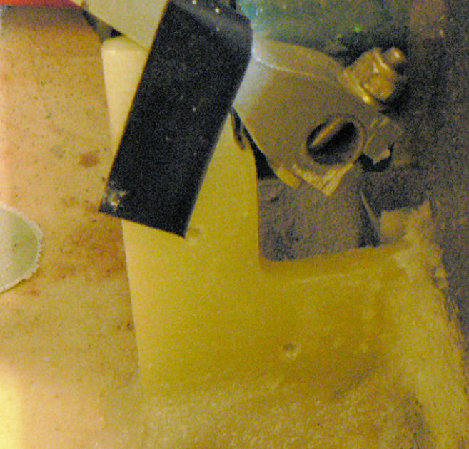
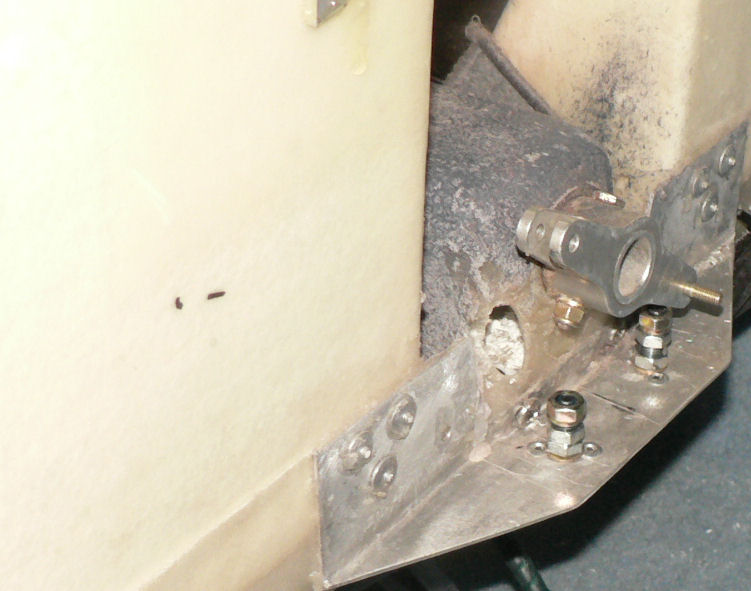
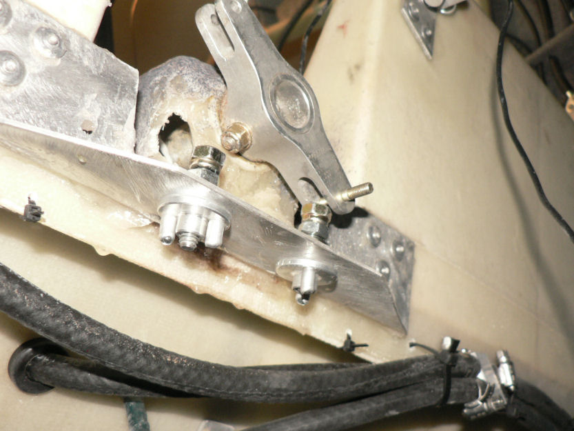
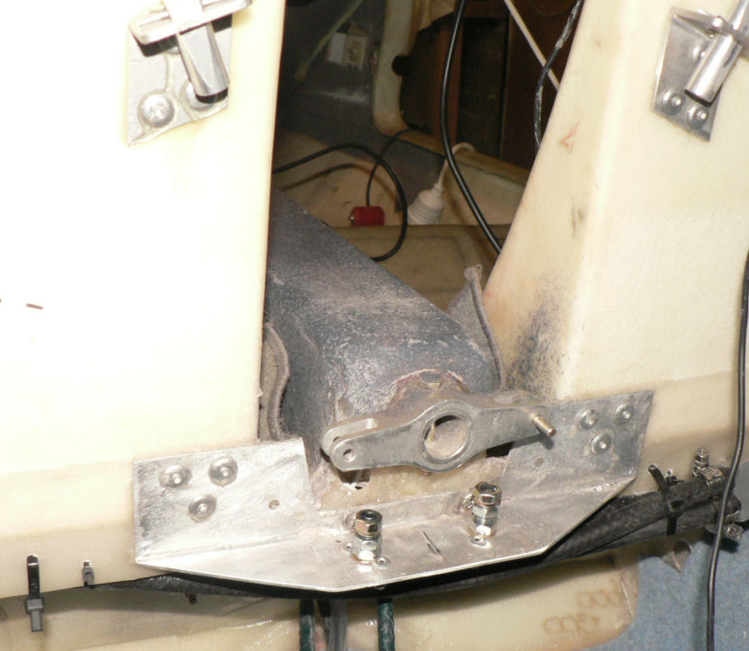
31-01-2008 Removed the panel again to get at the wiring. Removed about 20 mm from the bottom of the Centre Forward removable console before drilling new mounting holes and changing the fuel lines lengths involved. [ATTACH]4831.vB[/ATTACH][ATTACH]4832.vB[/ATTACH] Moved the electric fuel pump up a bit and a bit closer to the fuel cock to give a better curve to the line up to the filter & fire wall connection. [ATTACH]4845.vB[/ATTACH][ATTACH]4846.vB[/ATTACH][ATTACH]4847.vB[/ATTACH] Remounted the magnetic compass on the pilot side top of the panel to get better alignment with a/c. Discovered the screw in the back of the compass that allows you to level the compass laterally - it is sitting on a sloping surface as it is almost in front of the pilot. Used brass screws, washers and nuts to mount the compass. Shall have to put some loctite on the screws as I do not have lock nuts on the bolts. [ATTACH]4833.vB[/ATTACH][ATTACH]4834.vB[/ATTACH] A few more cables and wires need to be secured behind the panel mostly using cable ties. Make sure that nothing can get fouled by feet or controls after the panel is in its normal position and when the aircraft is airborne. [ATTACH]4835.vB[/ATTACH][ATTACH]4836.vB[/ATTACH][ATTACH]4837.vB[/ATTACH] I have probably used about three or four times as many cable ties as will end up on the aircraft and I don't think I am finished yet. For the inexperienced like me the cable ties were very daunting until I had had a few attempts. Once you have tied up a number of bundles it becomes more obvious as to how untidy it all is. In the pics below the fibreglass supporting the retained nut for the panel just above the choke control was dislodged and fractured. It was repaired by aralditing in a flat piece of scrap fibreglass behind the supporting glass and a new pair of CSK 3/32" pop rivets inserted. [ATTACH]4838.vB[/ATTACH][ATTACH]4844.vB[/ATTACH] The last few pics show the control stick stop and the throttle lever stops after curing. [ATTACH]4839.vB[/ATTACH][ATTACH]4840.vB[/ATTACH][ATTACH]4841.vB[/ATTACH][ATTACH]4842.vB[/ATTACH][ATTACH]4843.vB[/ATTACH]
-
30-01-2008 Removed the instrument panel to fit the slip & skid indicator. I checked the alignment of the panel with the aircraft door sills and they appear to be within about 1 or 2/10 degree of being aligned. [ATTACH]4824.vB[/ATTACH] So lined up the square edge of the instrument with the vertical edge of the panel. Using the aligned instrument as a template drilled holes to match and inserted black brass screws to attach instrument. Trimmed off the excess length of the screws to minimise chance of short circuits on wiring for indicator lights. The glass tube in the slip & skid indicator is spring loaded and the black "lines" are black nylon like material on the outside of the tube so they can be adjusted manually after the aircraft is flown - does this mean that it will only slip on cross wind landings!! Installed forward end of centre console. Attached it with retained nuts and pan head screws. Some rearranging of radio jack wiring, electric fuel pump power and low level float switch in header tank was required. Fuel pump was raised slightly to minimise air locks oin fuel lines. [ATTACH]4825.vB[/ATTACH][ATTACH]4826.vB[/ATTACH][ATTACH]4827.vB[/ATTACH] After looking at the job and photos I think I should trim about 25 mm off the bottom of the forward centre console so it can be lowered 25 mm to improve the routing of the fuel hose from the pump to the filter and firewall and make it easier to service the in-line fuel filter.
-
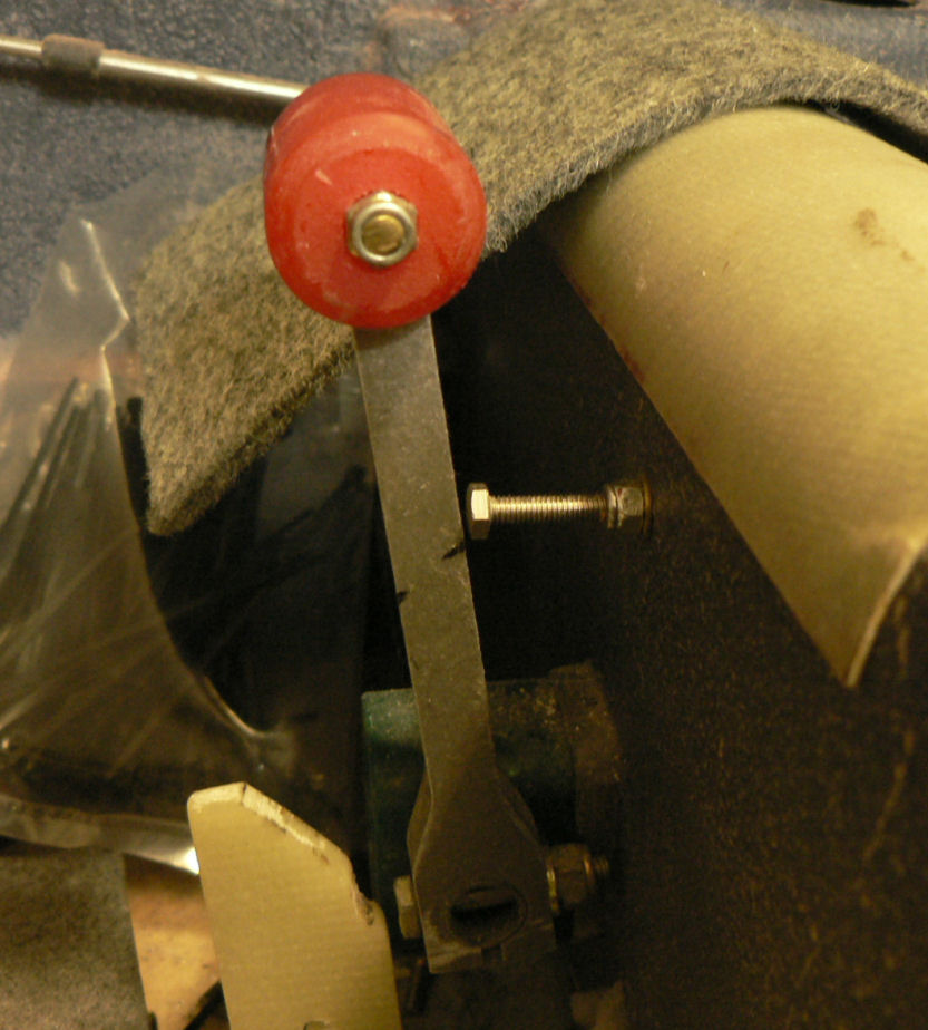
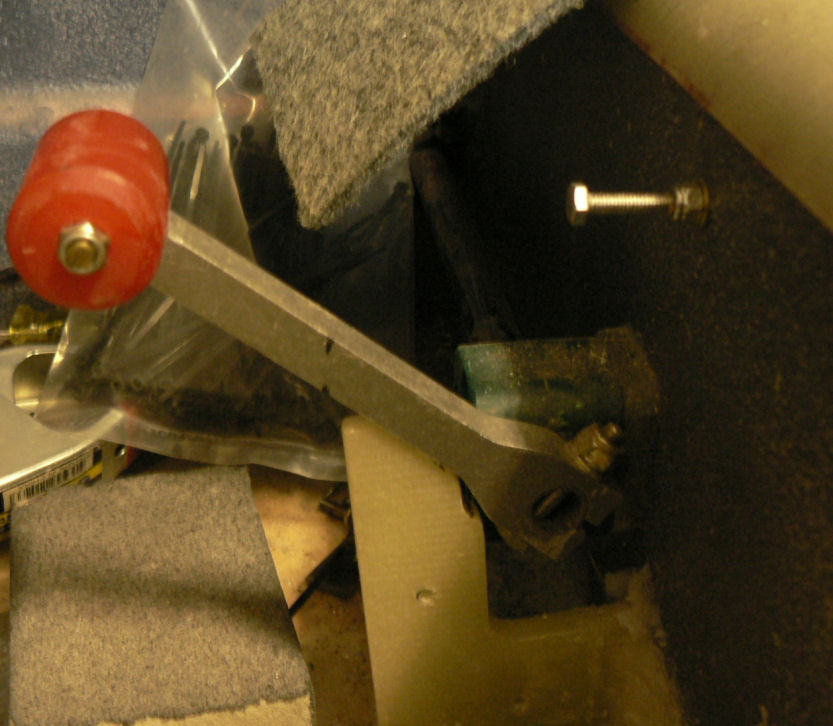
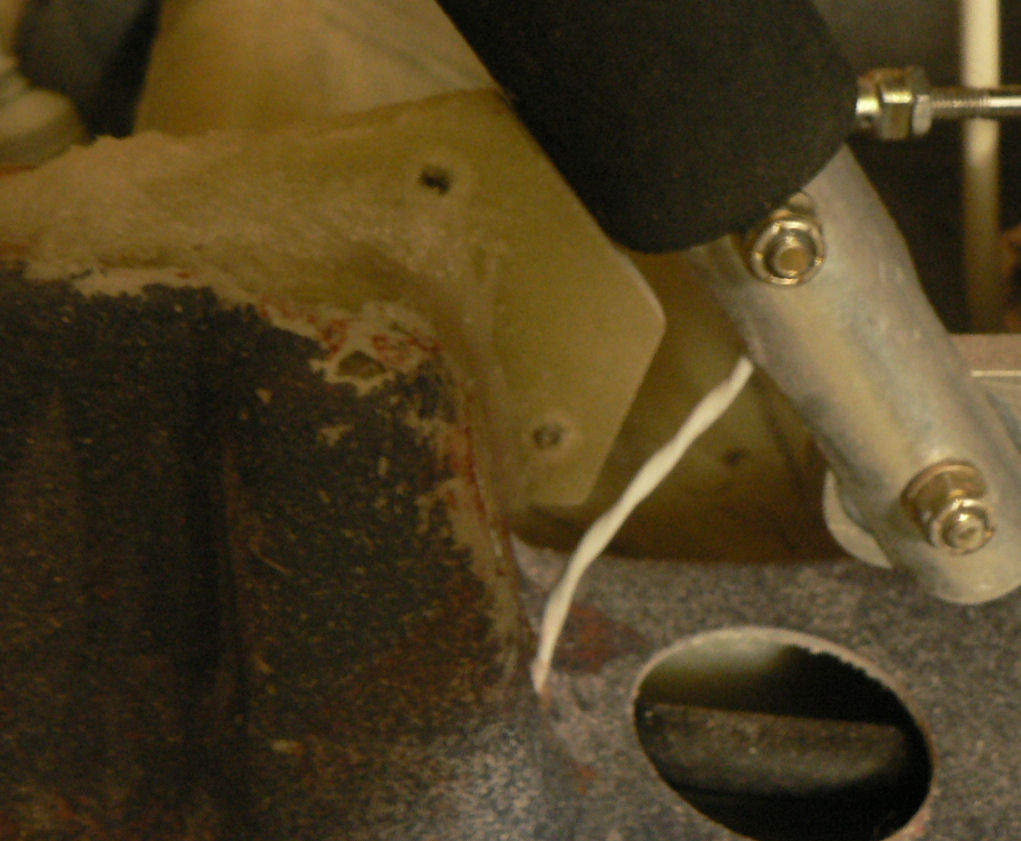
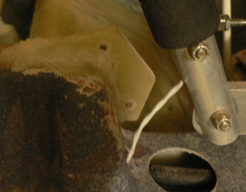
29-01-2008 Added some more lining to the luggage forward roof area which had not been completed previously. Easier now when I apply a coat of adhesive to the lining and the fibreglass. Wait till both surfaces are tacky before attempting to apply the lining with no wet liquid liquid adhesive showing otherwise it will fall off. Prepared both areas for application of flock by removing paint, sandpaper areas to be flocked clean with acetone apply epoxy to area of joins apply flock as a fillet to the joining materials. Epoxied & flocked the throttle limit to the floor below the throttle lever. [ATTACH]4811.vB[/ATTACH] [ATTACH]4812.vB[/ATTACH] Epoxied the stick forward limit to the centre console in front of the control stick. [ATTACH]4813.vB[/ATTACH] Record Times,temp,relative humidity till cured. Check position of stops periodically until initial curing has occurred.
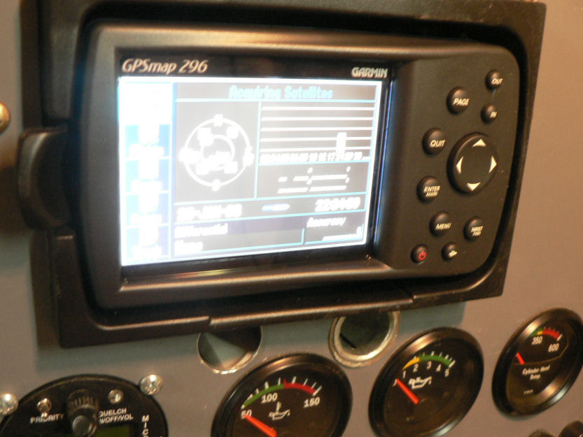
-
28-01-2008 Hi Chris at this stage no artificial horizon - would really like to start again with a new fibreglass panel (with a few sheets of spare panel material). Although I do like the idea of those Tru Trak combinations at around $US1000 plus at least an automatic wing leveller (plus a transponder so I could legally fly above 4,500 feet AMSL or 3,500 feet flying east as our thermals would mostly end up above that height even on "blue" days when they are not marked by cumulus clouds). Today I vacuumed out the luggage area of the J160 plus the tops of the seats and the waste from fitting the new fuel hoses and the wing tank fuel cocks. Modified the aileron limit bolts by attaching the umbrella bolts with pop rivets under the angular plate. "Loctited" a locknut to one end of each limit bolt and fitted it upside down on the bolt. [ATTACH]4803.vB[/ATTACH][ATTACH]4804.vB[/ATTACH][ATTACH]4805.vB[/ATTACH] Fitted the bolts so that they could have two lock nuts on each one - one against the angular plate and one against the locktited nut that will act as the limit position. It will be easy to adjust the bolt-nut height by hand and then lock in position with a single spanner Lowered the Garmin 296 caddy about 4 mm so that the built in antenna can be deployed vertically while the 296 is mounted in the caddy. The antenna can seem to work over a 90 degree range if unencumbered when not in the caddy. Temporarily mounted the instrument panel and no circuit breakers went off and no wires were too short. The radio and other live items continued to work. The aircraft was inside the garage with a single brick wall around three sides and a large closed wooden door behind it and it was close to a normal house wooden door facing outside and the GPS 296 was able to pick up a single satellite. So it will probably be fine with a horizon unencumbered by brick walls, trees and a tile roof. [ATTACH]4806.vB[/ATTACH][ATTACH]4807.vB[/ATTACH][ATTACH]4808.vB[/ATTACH][ATTACH]4809.vB[/ATTACH] Chris's solution would have been better and far easier to fit the angular caddy which he says can be surface mounted on the panel and improve the angle view if it is not mounted in front of the pilot. I have modified my caddy a bit to give a slight angle towards the pilot. I also have a tinted windscreen so that should help the readability of any lit glass instruments - hence the instrument lights in case it makes it too dark. But there are no lights on the flying instruments! PS See the fencing wire - it had many applications around the construct.