Ross
-
Posts
729 -
Joined
-
Last visited
Content Type
Profiles
Forums
Gallery
Downloads
Blogs
Events
Store
Aircraft
Resources
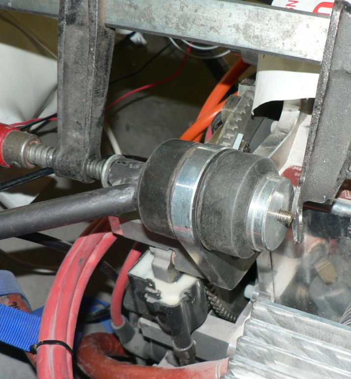
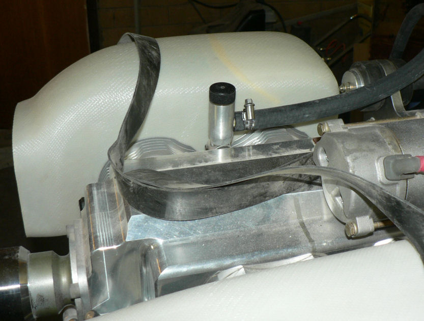
Tutorials
Articles
Classifieds
Movies
Books
Community Map
Quizzes
Videos Directory
Everything posted by Ross
-
Hi Jim I have sympathy with your dilemma over the description of the Jab aircaft. Most people talking of Jabs on the forum do not differentiate between the models and they vary from something like 470 Kg MTOW with a 1600 cc motor cruising at about 80 knots to 600 Kg MTOW with the 3300 cc 6 cyl motor cruising at 120 knots or thereabouts. Generally speaking they come in two versions for each model. The Certified factory built ones generally have C attached after the model name so a J160C is a factory built certified plane with the 4 cyl 2200 cc motor. The certified one can probably be registered as RAA or GA. The J160 is the kit built version of almost the same plane but there may be slight differences in some of the equipment but essentially the same a/c with the 4 cyl 2200 cc motor. The uncertified Kit can only be registered RAA . The kit version of the J160 came out early 2004 I think and I have kit #14 in the J160 model. Kit versions cannot be hired or used for training generally. Kit versions can be maintained by their builders who are granted L1 status as owner kit builders. The certified version of it, J160C came out later in 2005 which can be used for hire or instructional flights if maintained by a L2 or LAME. The model numbers have nothing to do with the engine size although sometimes part of the model number has some meaning like the number of seats, For details of most of the Jab models see their website for their specifications as well as drawings & options. http://www.jabiru.net.au/ Regards
-
Icam Commiserations for a frustrating time ahead for a while. I had a similar experience for the right eye earlier this year and will probably have to do the left one in 2008 or 2009. My optometrist did not diagnose my right eye cataract early so that at least one previous new set of glasses was a complete waste of money and a very frustrating time until I worked out that the problem must be a cataract . Then it took another almost six months before I could get another appointment, then a referral to the specialist in Wagga and then be scheduled for the lens implant day surgery operation and the new glasses test a month later at least and then wait for the glasses to come a fortnight later! A real test of patience! It seems that even the specialist will recommend delaying doing anything about it until it is well developed. A possible reason is that there are some failures of the operation but usually something like 90 to 95% success. My solution was to just wait for the month to get the new glasses before flying because the eye takes that long or longer to settle down. I found I could drive quite safely with no glasses to start with but it would be illegal! without an RTA eye test I presume. So wearing my current glasses at the time just made my eyesight worse! My experience was a bit frustrating as I ordered Poly Carbonate "glasses" as they are resistant to Acetone (building a J160) and less susceptible to scratching than previous glasses I have owned. I had to wait a bit longer, then as the optometrist staff sent the wrong prescription to do the lenses so they had to be done again. That was about March or April 2007 and I am due for another check up in Wagga early December. I suspect the left eye cataract has deteriorated some more and the right eye with the new lens implant has changed a bit. The right eye implant lens has a UV filter built in and a slight blue filter which gives a noticeable reduction in glare off the road & sky when driving into the sun from Wagga to Leeton. The eye surgeon recommended the permanent wearing of "Fitover" sunglasses (about $50) when outside the house which I find hard to do although I will usually wear them on hot sunny days but they tend to give you early dusks unless you remember to take them off! The polarising "Fitovers" seem to be a big improvement on most other cheap sunglasses that I have worn. I only clean them by rubbing with fingers under running water and then drying with a very fluffy rag to reduce the risk of scratching. Rubbing with a brand new handkerchief is not recommended. There are pilot versions of the "Fitover" glasses that I was not aware of at the time I bought them. Regards
-
The phone? After going to Sydney with a bad chest infection then back to Leeton then to Mildura for the weekend they put me in hospital when we returned to Leeton from Mildura-got out today still coughing but an imrovement. However I found out that my cousin's husband Eric Muntz is building a Jab230 in Albury and he is installing a Bluetooth interface in his A/C which he got or is getting some Wagga techo to install. I think it involves small screen display installed in the panel that displays the current state of the connection. What might Bluetooth do to a GPS reception and transponder? I do not have any more details at this stage as I was having difficulty holding a conversation with my continuous coughing once I started talking - quite a disadvantage in a large family get-together. I shall try and get some details by e-mail over the next couple of days. Regards
-
Hi Crew Has anyone experience of what make and model mobile phone will interface with the aircraft headphone system for use in the next G system that replaces the CDMA network. I have heard that some Next G phones have a "tick" implying suitability for marginal area operation. But they also need a suitable socket for ease of interfacing with the AC system. The phone needs to be able to be plugged into the AC headphone system without causing additional battery drain on the phone battery and only coming live with an incoming call or the dialling of an outgoing call.
-
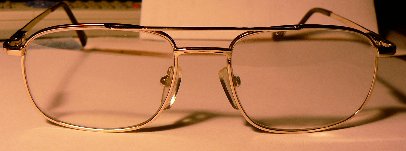
Hi Crew I have not been active on the J160 kit as I came back from Sydney with a lung infection that is slowing me down more than normal. But I thought to offer the information that I eventually found after getting a new pair of multi-focus glasses on 30 April 2007 after a cataract operation. I asked for safety glass because of the damage I was getting to my glasses from sanding and handling the epoxy and acetone used in the kit construction. However the optometrist suggested they would be too thick & heavy and still be subject to scratching etc. She suggested Poly Carbonate as being not affected by acetone and still having a good refractive index to give reasonably thin and therefore not as heavy as lenses made in glass. So below is a pic of those glasses after six months & $Aus327 for the prescription lenses not including the frames. They have very minor scratch marks on them which have not shown in the photo and I can barely see the few very shallow scratches using a set of reading glasses. [ATTACH]4207.vB[/ATTACH] It is certainly a big improvement on the damage that the original glasses were suffering.

-

CTAF(R) frequency change for Wagga Wagga
Ross replied to Captain's topic in AUS/NZ General Discussion
Hi Geoff I will check frequencies again when I get home. Regards -
Thanks Darren The nearest I am likely to get is this forum before we drive past for home on Thursday morning. Regards
-
Hi Geoff I just tried to ring geoff in Adelaide to discover that he was discharged yesterday which I think is earlier than anticipated. So if you read this Welcome home Geoff Regards
-
Roger That sounds good to me. I hope that you are having a better flying day than Sydney is at the moment. Totally overcast here with big black things hanging over the ranges. Regards
-
Thanks Disperse I don't think it's going to happen. The women have the next few days mapped out with our son coming over this afternoon. Anyway got both the daughters front verandah marked as a waypoint and "The Oaks Ap". I was trying out the new "Garmin 296" in the car (our first & second Garmin car power leads were no good) and it had about one hour of battery power left at the Yass service centre. So that was about 3.5 hours used with about an hour left and three hours of driving left. We have already had a brand new power lead replaced with similar results - it was very hard to insert in the socket on the Garmin and resulted in the lead coming apart on pulling it ou for the first time. I am still waiting on my second replacement. Regards
-
Hi Bruce Thanks for that. I must admit I did not try very hard thinking that there were lots of helpful people out there that knew where the best info was. Thanks again.
-
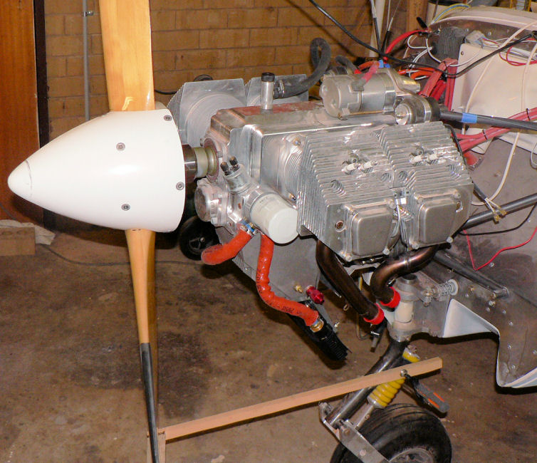
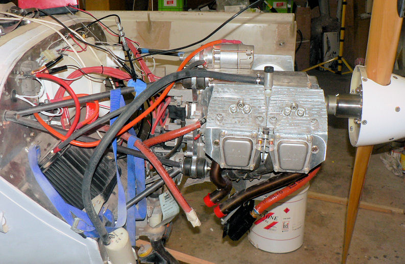
29-10-2007 Had to reinstall two of the cam locks as they were still too tight after dressing the filled areas with a small emery wheel on the mains powered Dremel. The battery powered Dremel is fairly inadequate for most of the jobs I wanted to do with it in this build. Installed sensor wiring for oil pressure & oil temperature gauges. Installed aircraft electrical power for oil pressure & oil temperature gauges. Spun the motor using the starter motor. With mains switch ON & 2 litres of oil in the engine, oil pressure ran up to about 350 kPascals (middle of the green) with cold motor & disconnected plug leads with spark plugs installed. There were no obvious external oil leaks with the oil cooler in the circuit. The Oil temp gauge just moved off the low stop once the mains switch was turned on. It got about halfway to the lowest reading on the gauge. Carport temp at the time was about 25 degrees C. Eventually found & replaced the exhaust covers which I should have removed before spinning the motor. To be continued in November.
-
Hi All The Microair M760 revision N that I have has a DB-25 connector in its wiring harness. Pin 24 Brown of the DB-25 is designated as AUX Audio signal (Music) input Mono. Pin 25 Gray of the DB-25 is designated as AUX Audio ground input Mono. Regards
-
Hi Mazda Thanks for your effort on that lengthy explanation. I shall have to see if I can translate it all into action. I was surprised to find no response to a Google search for "The Oaks" that referred to the airfield. Regards
-
Hi Yenn Years ago we lived on a farm 20 miles downstream from Narromine on the Macquarie River near Gin Gin. Gin Gin was a Macquarie river bridge crossing the river on the road from Trangie heading North and was another five to ten miles or so further downstream from where we lived. Regards
-
CTAF(R) frequency change for Wagga Wagga
Ross replied to Captain's topic in AUS/NZ General Discussion
Hi Captain Likewise a change at Griffith & Narrandera Regards -
Hi "The Oaks" Crew I am visiting Sydney this coming week, Concord specifically. Driving down tomorrow, Saturday. I hope to have a look at "The Oaks" on Sunday afternoon if my daughter will let me or possibly during the week. I need directions on how to get to "The Oaks" from the M5. I know where the M5 is! Regards
-
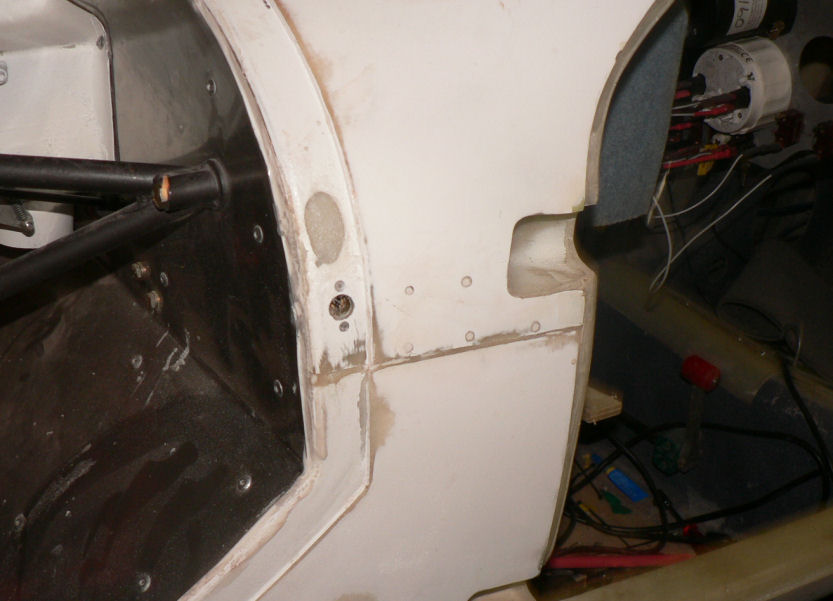
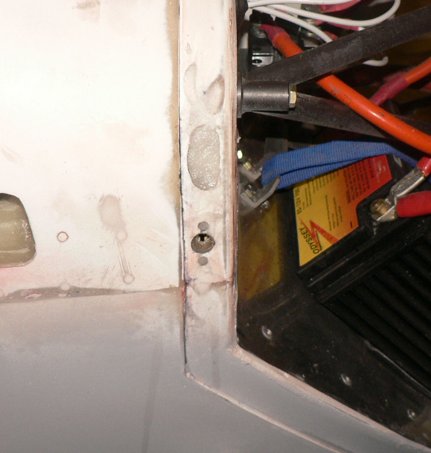
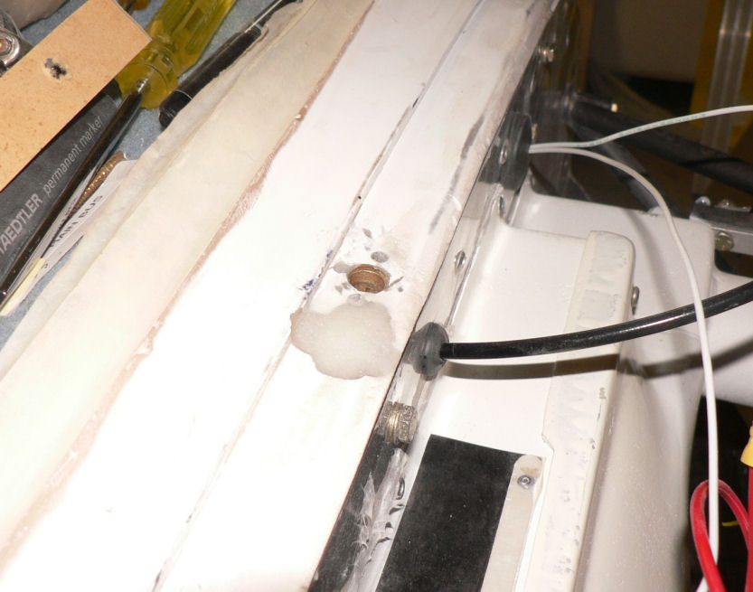
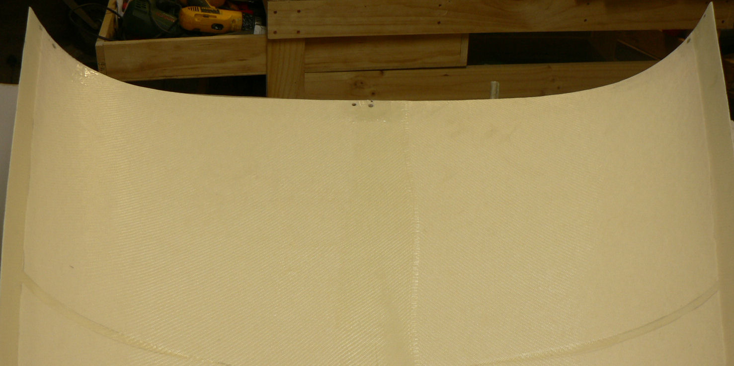
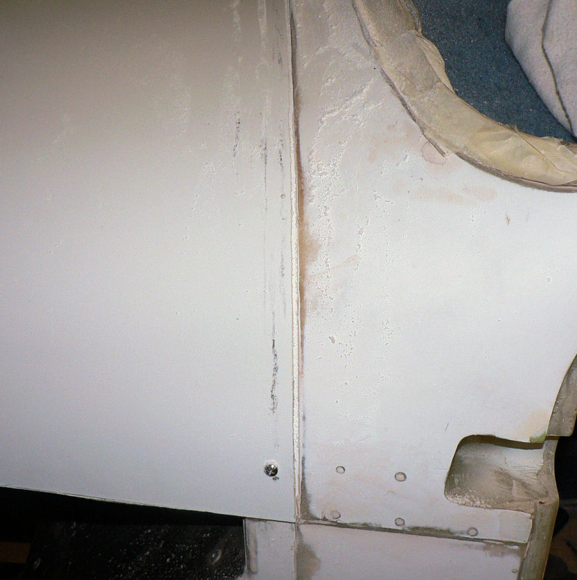
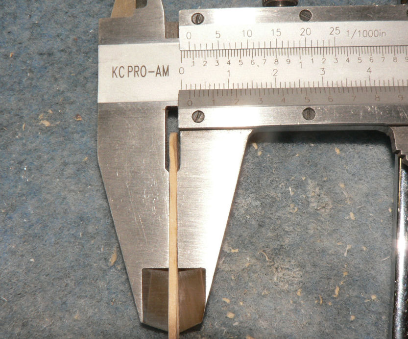
25-10-2007 The non magnetic (brass) feeler gauges arrived today @ $16-45. They actually phoned to say it had arrived! Continued to trim the top cowl until it fitted OK. Installed the cam locks as per the drawing on the top cowl - Not OK. They were in conflict with other parts of the aeroplane - I should have learnt by now. Removed cam locks. Reinstall cam locks for top cowl in different locations. Needed to relieve the installation location of the cam locks as the material was too thick to allow the camlocks to work by a couple of mm. Filled old cam lock holes with epoxy flock. Pics 1-3: New cam lock locations and filled holes Pic 4 : Duct retaining springs lock wired onto #1 & #2 cylinders. Battery Earth wire connection to engine. Pic 5: Glass over the extra holes in the top cowl - hope I have filled the right ones. [ATTACH]4123.vB[/ATTACH][ATTACH]4124.vB[/ATTACH][ATTACH]4125.vB[/ATTACH][ATTACH]4126.vB[/ATTACH][ATTACH]4127.vB[/ATTACH]
-
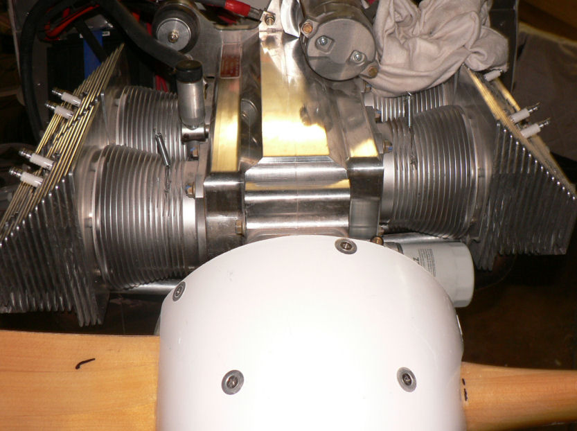
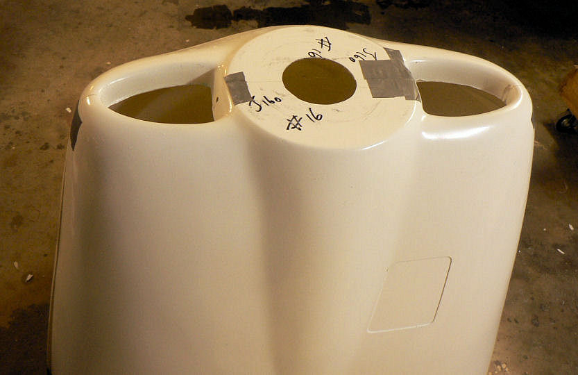
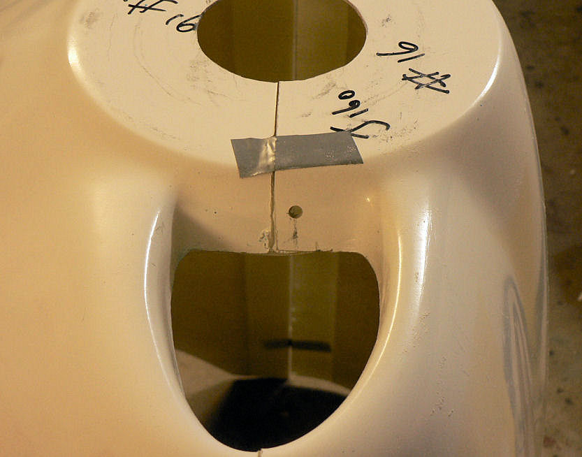
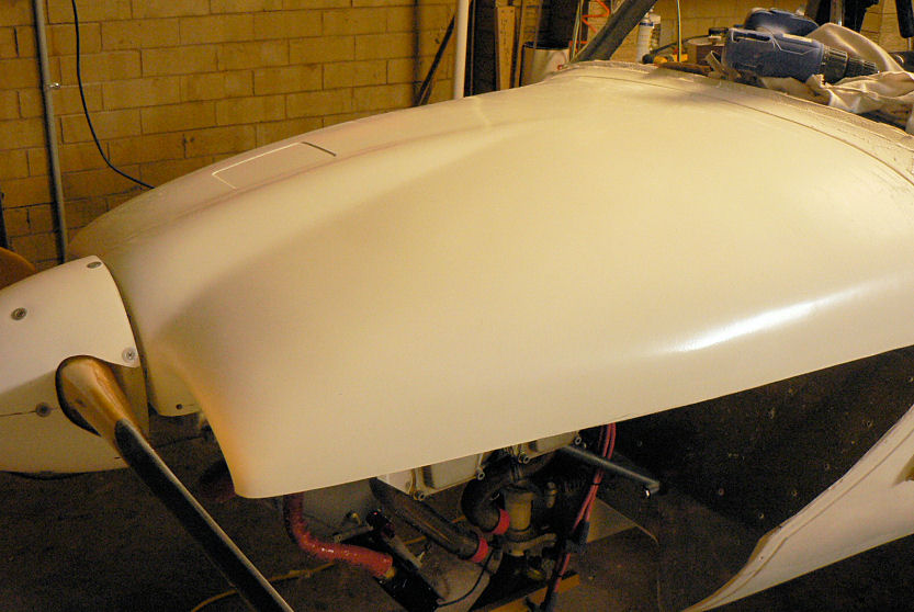
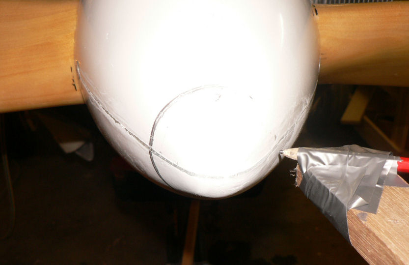
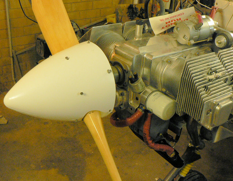
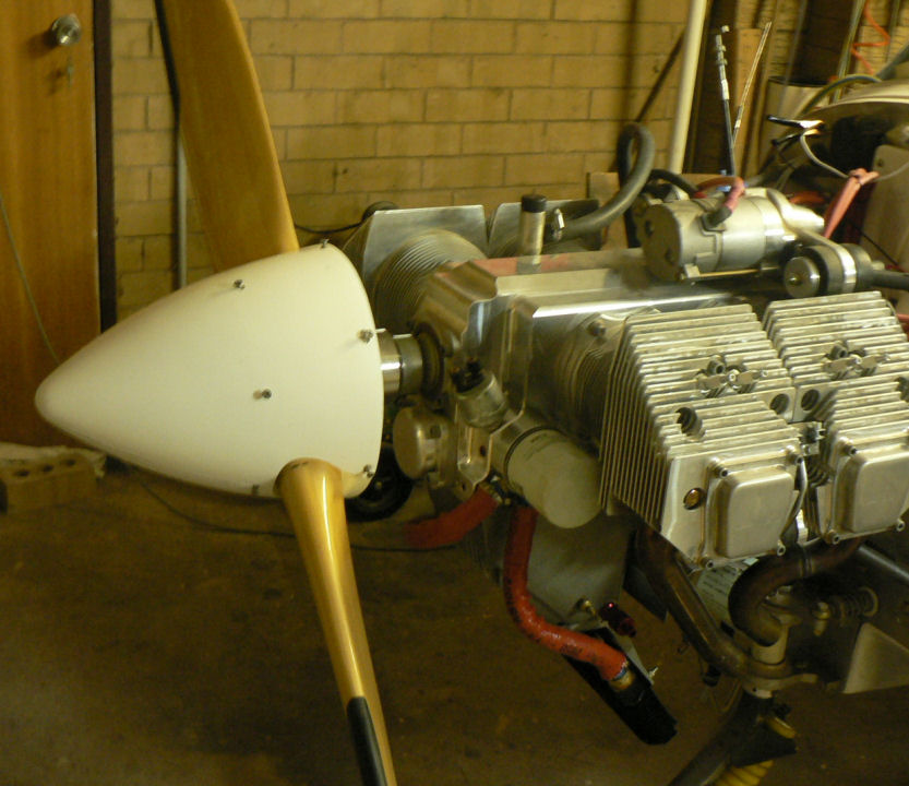
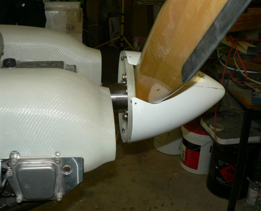
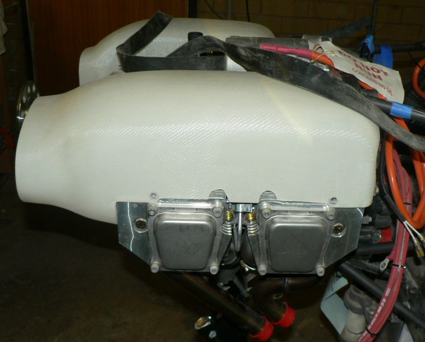
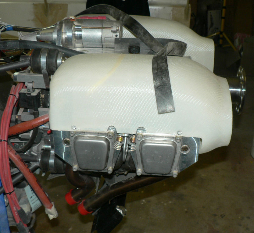
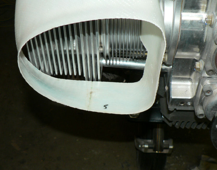
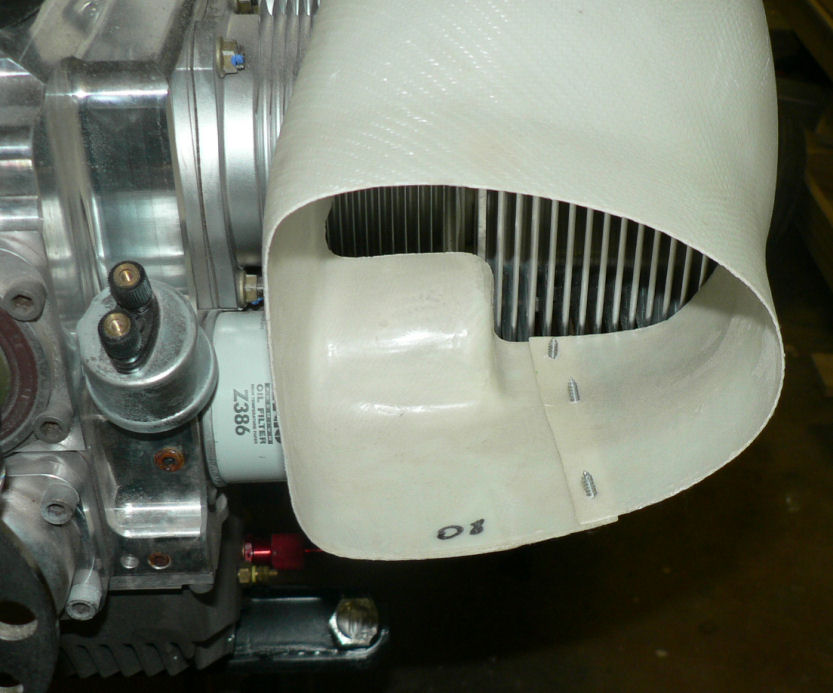
24-10-2007 Looked for a non magnetic set of feeler gauges in our local engineering supplies shop for the second time; still no stock; so I ordered a set. Today was a mixed bag and I did not remember to take all the pics to show it. Fitted small Aluminium brackets to the ram air ducts and lock wired springs to #1 & #2 cylinders to hold down the ram air ducts onto the cylinders. The drilling for bolting to the tappet covers and fitting of the ducts had been done previously. Had to remove the ducts to get enough room for a hand inside the duct as it requires a 1/8" steel washer on the rivet inside the fibreglass duct to secure the loaded rivet. I still need to reinforce the join in the ducts with glass and epoxy and also to mount & epoxy the air cooling tubes for the two coils. I need to match the length of the ram air ducts to suit the cowls once they are fitted and also to fit the flat rubber (neoprene?) material on the front of the "ram air ducts". I rang Jabiru to establish that a 90 mm diameter hole was required not a 90 mm circumference hole??? in the front of the mated cowls. Myles also said that the engine with full power would pull to the right. So this has to be allowed for in setting up the cowls. I asked him for the desired clearance from the back edge of the prop spinner to the front of the cowls. He said 6 mm or a bit less but up to 8 mm was OK. The cowls were taped together with duct tape - some cleaning up of mating surfaces is required. They were drilled with 2 x 1/4" holes to take the quick couplings at the front inside the air holes. The centre of the joined cowls was found and a 90 mm diameter circle marked out and cut out using a jig saw. I decided to start with the top cowl. The oil cooler will make the bottom one impossible to fit without modifying the old style cowl #14 kit. Sat the top cowl on its rear mounting position to find that it is too long by a few mm and will need to be turned a bit to the right and lifted at the front to centralise the spinner in the cowl face and allow for engine movement under full power. This means that the back edge of the cowl has to be trimmed a variable amount from each side towards the centre top rear of the cowl which would be the biggest trim. It will also need more off the right hand side than the left to lean it to the right - how much to allow for moving under power ?? Once I get that cowl looking to be a good fit I will work on mating the bottom cowl to it. All this is assuming the engine is mounted in the right place with the correct alignment and clearances. I have no way of knowing more about that until the engine is fired up to full power and ultimately until the test flight. At the stage of the last two pics the top cowl still needs to come up at the front by 10 mm or more requiring more material to be dressed off the rear end of the cowl. The cowl in the last two pic is attached by 2 temporary SS self tappers, one on each side at the bottom rear edges of the top cowl and the front is sitting on the prop boss in both pics. The cowl had been trimmed by about 4 mm along the rear edge before I anchored the bottom left corner. After more trimming emphasising the RHS the RHS bottom was anchored with a self tapper before the lat two pics were taken. It still needs a bit mor trimming to finish it off. [ATTACH]4118.vB[/ATTACH][ATTACH]4119.vB[/ATTACH][ATTACH]4120.vB[/ATTACH][ATTACH]4122.vB[/ATTACH] I am using a "Dremel" with a relatively wide wheel of coarse emery, maybe 10 mm wide tread, which is quite good for this job. I draw a pencil line along the edge as a limit for each pass and dress up any big bumps as I go before they get too big with each successive dressing of the edge. Will finish it off with a long hand held emery block.
-
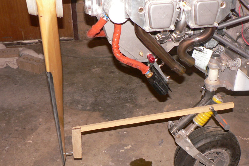
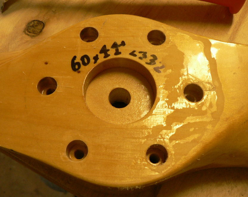
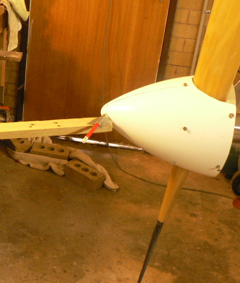
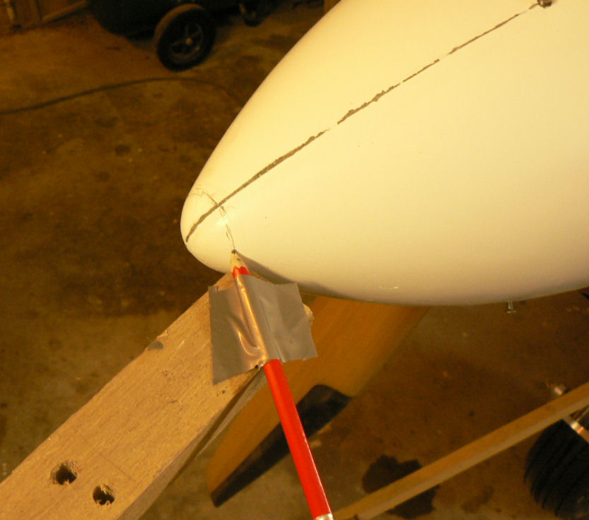
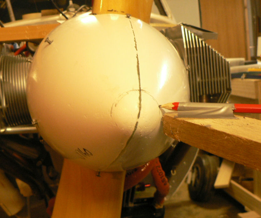
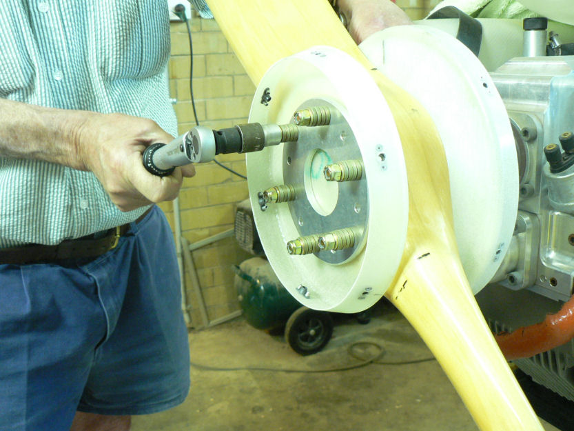
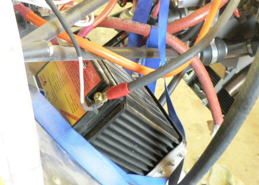
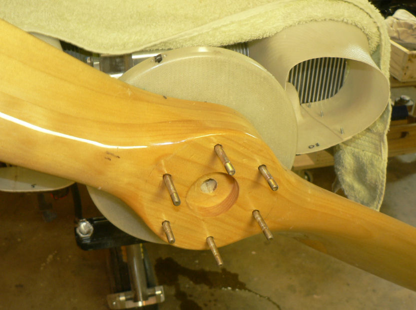
23-10-2007 Jamie at jabiru suggested to remove a flat washer, not a Bellville washer pair, from the prop bolts to gain enough length for the Nyloc nuts to be safe. Pics: 1 - 7 Removed a spark plug from each cylinder to reduce loads when checking the prop tracking. Set up a stick on the front UC leg to test the tracking of the prop when bolts tensioned to 6 ft lbs = 72 inch pounds. Prop was out by about 4 mm variation from one blade to the other - first suggestion in construction manual made little difference. It was to torque an extra 2 ft lbs for three bolts on the high side of the prop. So I tried this in two stages increasing the torque each time. No joy. The high side of the prop appeared a little rough so I did a lite scrape on it. Hooked it up again and checked the tracking of the prop still more than 2 mm difference. Removed the prop again and sanded it litely on the high side of the wooden prop boss to level up the bumps. [ATTACH]4103.vB[/ATTACH][ATTACH]4104.vB[/ATTACH][ATTACH]4105.vB[/ATTACH][ATTACH]4106.vB[/ATTACH] [ATTACH]4107.vB[/ATTACH][ATTACH]4108.vB[/ATTACH][ATTACH]4109.vB[/ATTACH] Refitted the prop tried the tracking at 72 inch lbs torque on all bolts and it was less than the 2 mm limit at about 1.75 mm - OK. Spinner Tracking: Pics 8 - 11 Set up a pencil mounted on a stick to track & mark the spinner. Spinner was pushed around to optimise the tracking and the screw holes relieved accordingly. Needs a little more to be done after smoothing up spinner & painting. [ATTACH]4110.vB[/ATTACH][ATTACH]4111.vB[/ATTACH][ATTACH]4112.vB[/ATTACH][ATTACH]4113.vB[/ATTACH] Pic 11: Earth lead from battery to earth post replaced cable. [ATTACH]4114.vB[/ATTACH] Pic 12: Spinner with SS screws and CSK washers fitted. [ATTACH]4115.vB[/ATTACH] Pic 13: Other side showing new earth strap fitted - need some black heat shrink tube on it. [ATTACH]4116.vB[/ATTACH] Replaced spark plugs & covers over exhausts and carburettor intake.
-
Hi Bigglesworth I bought a small 8 ohm speaker, $14 at Tandy shop from memory, plus necessary combination plug & socket adaptors so I can listen to the radio in the workshop w/o using the headphones. Regards
-
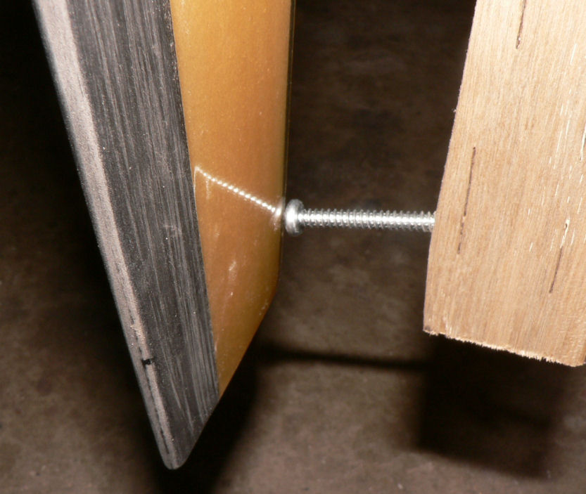
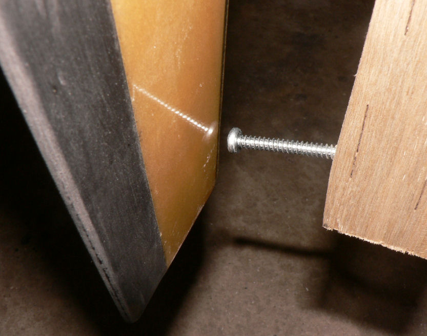
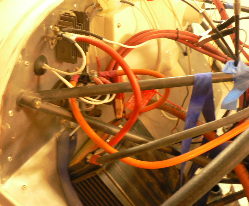
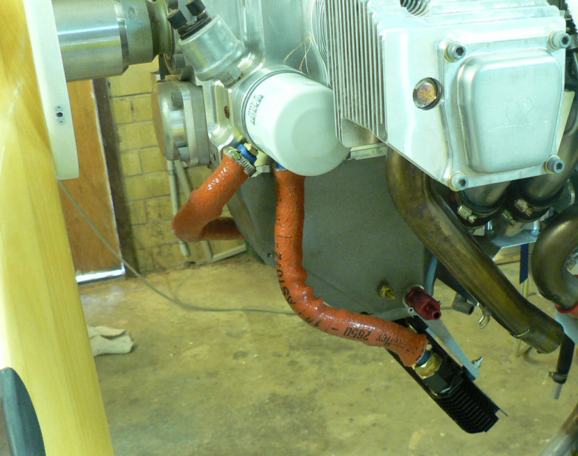
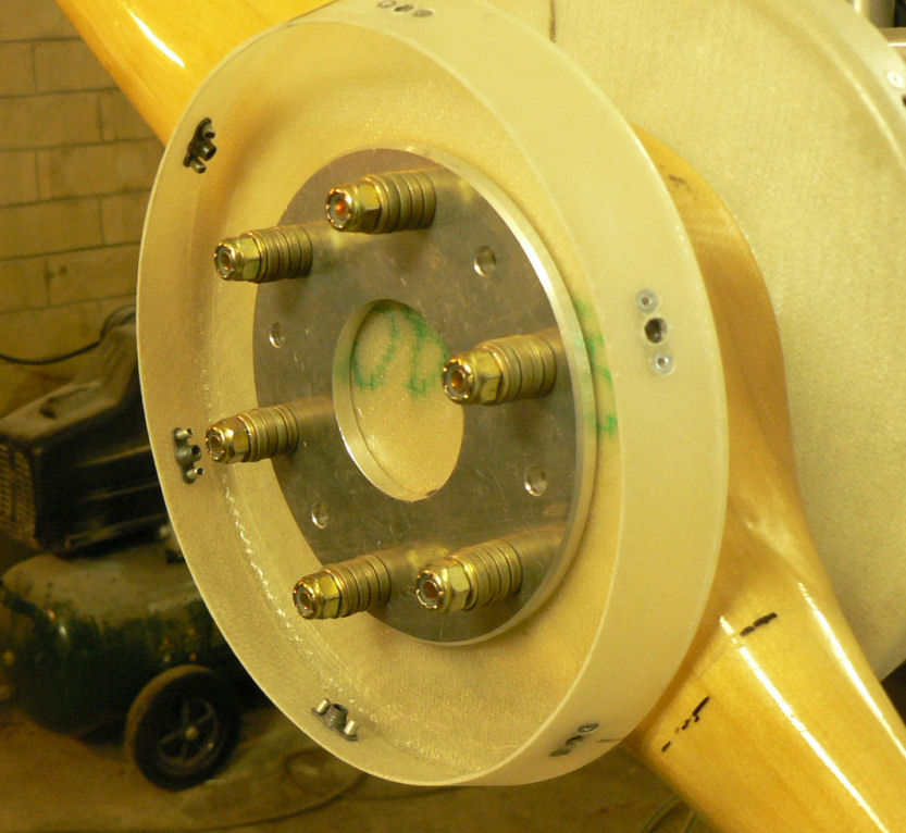
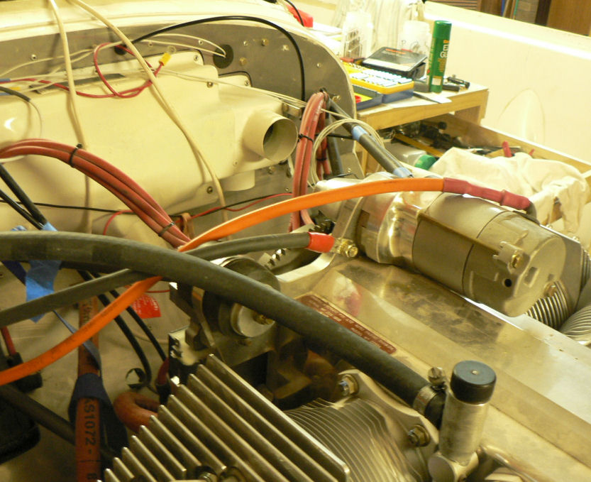
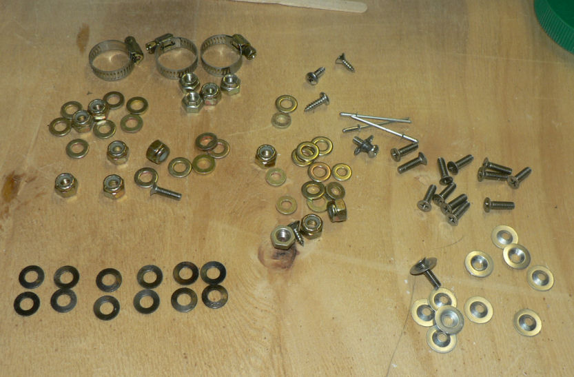
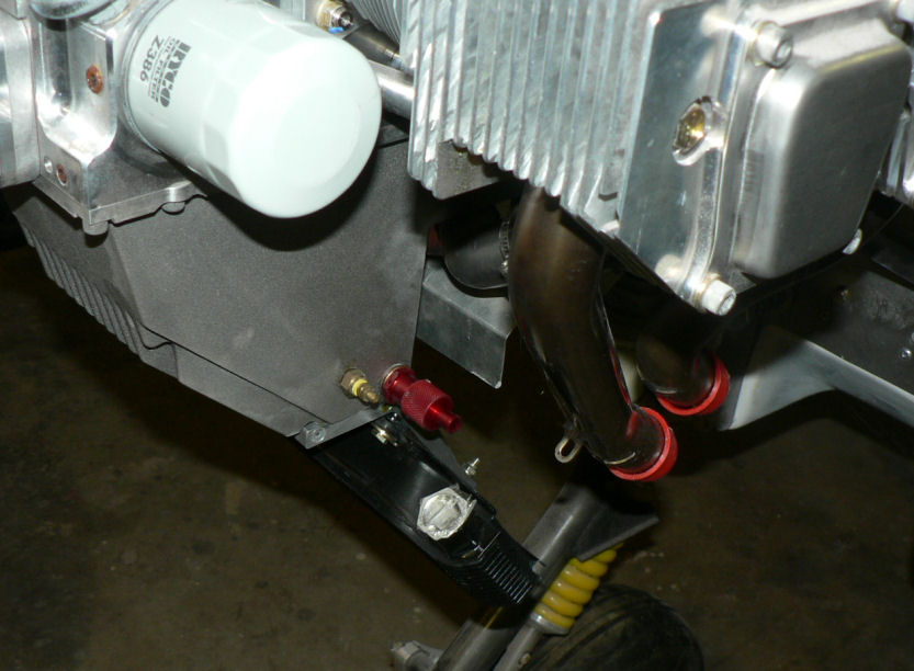
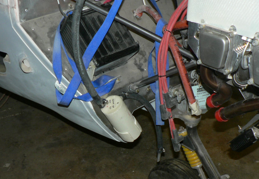
22-10-2007 Pic 1: Fitted oil cooler adapter at oil filter. It has been installed with O ring side facing the engine otherwise filter oil flow could be shut down. There is a small bypass hole built into my adapter. Fitted the oil cooler hoses to adapter and oil cooler with fire retardant cover & clamps. Jabiru (prop bolt kit) packet arrived in mail today with;- 7 x Nyloc nuts AN4 49 x Bellville washers 9 x Flat washers 6 x Bolts AN4-37A with I think it was X 010 on the head. Removed superseded prop bolts. Fitted new prop bolt bolts each bolt with 8 Bellville washers, 1 flat washer and a Nyloc nut. Pic 2: Nuts tensioned to 6 pounds feet or 72 inch pounds in about three stages in order of #1 #4 #2 #5 #3 #6 and repeated as necessary. Pic3: Bolts are too short by about 1 size unless a Bellville washer pair can be removed see third photo. Pic 4: Need to check tracking not done yet - but spinner prefitted. Pic 5: Engine earth strap made up and fitted from battery to engine Pic 6: Engine earth strap at battery end. Removed spark plug leads from spark plugs. Added 2 litres of Shell Aero Oil to engine Removed 1 spark plug from each cylinder Removed exhaust pipe and carburettor covers Turned engine over clockwise a number of times. Spun engine on starter motor for 20 seconds or so a couple of times. Pic 7: Replaced spark plugs, but not spark plug leads, exhaust pipe & carburettor covers and turned on battery charger. Wiring of hoses and plugs yet to be completed
-
Hi Yenn and others Apologies for NOT having answered your responses before. Firstly I am doing bold & size 3 lettering because I find it far easier on my eyes. I had a cataract removed from the right eye earlier in the year and it is now great but the left eye also has a developing cataract which will need action soon. The eye surgeon in Wagga booked me in this coming December for an examination when he did the right eye. From what I understand most modern say after about 1970 or a bit later aircraft will not stay in a spin if the pilot does not intervene. If the spin is initiated and not held in it becomes a spiral dive with a rapidly increasing airspeed which in a glider will be catastrophic in a very short time. In regards to the excessive ASI only in the IS28 (in my limited experience). The problem is that it rapidly recovers from an accidental spin into a spiral dive but the only view and very sudden change out of the windscreen is solid earth. It almost goes inverted - very scary - with a very rapid increase in airspeed - do not blink. Need to recover to a normal attitude immediately as you will probably exceed max manoevering speed before you can get the nose on the horizon! The Blanik on the other hand does a fairly flat spin by comparison and only needs opposite rudder plus an easing of the stick to recover from a spin and usually can recover without the speed becoming excessive. You are starting the recovery from a not very steep nose down attitude although it is falling in the spin (not flying) at 80 knots. They all need their noses pointing at the ground until the spin is stopped and it starts to fly again with both wings flying instead of one only. Then can you lift the nose and live again! Regards
-
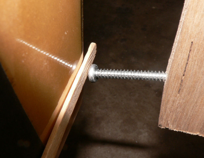
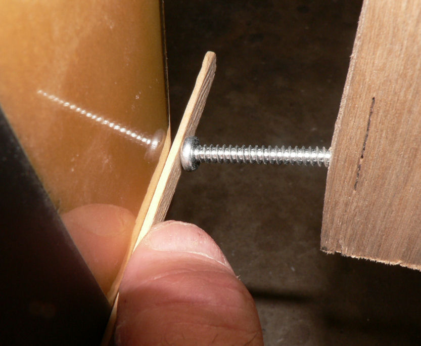
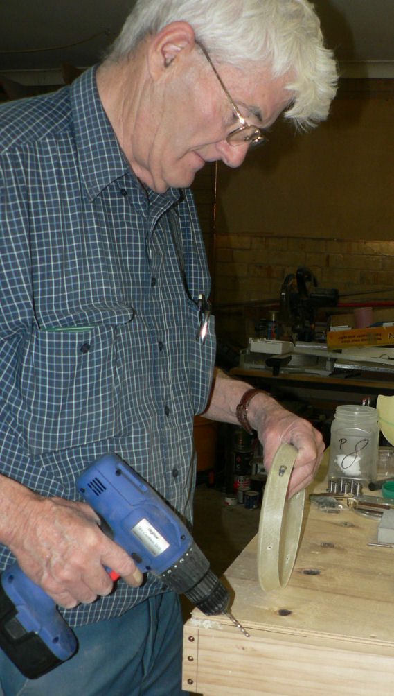
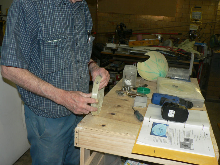
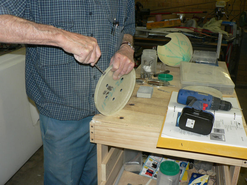
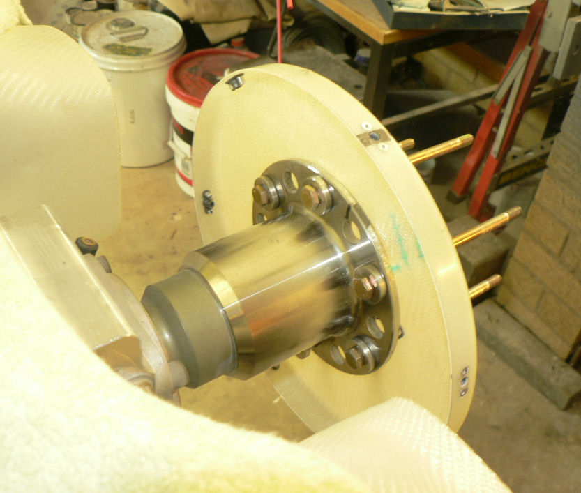
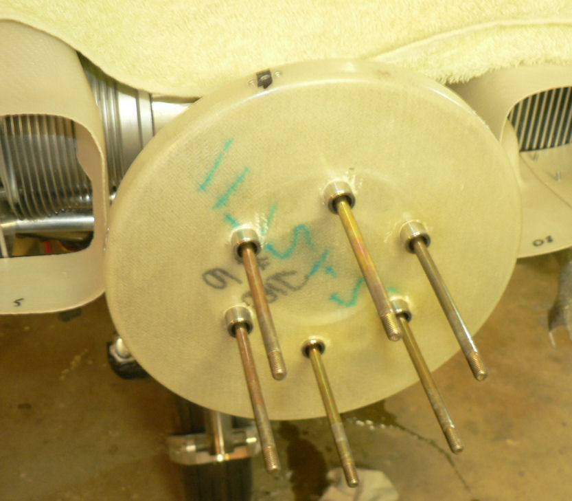
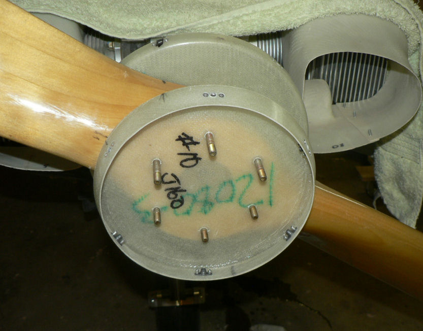
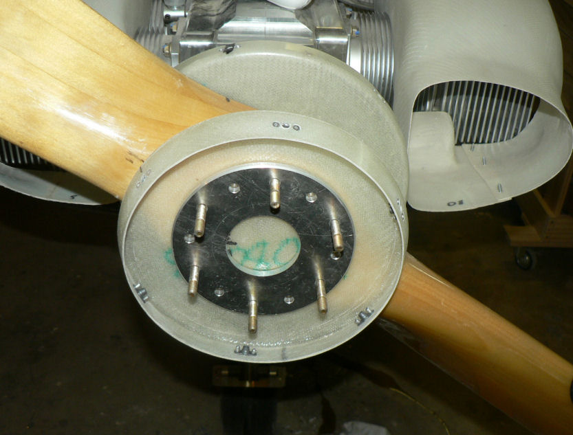
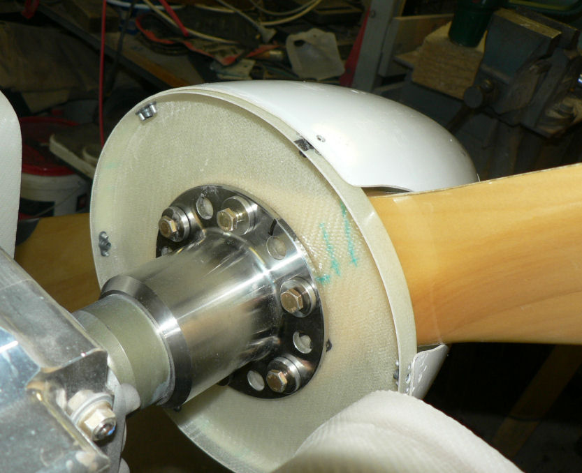
18-10-2007 This was more in the mode of an exploratory episode today not being able to complete the job because the prop connection is one of the things that has been changed so I do not have the new kit for it yet. Short description: enlarged the pilot holes in the 2 spinnner flanges out to 5/32"; used a retained nut with a screw in it as a jig for drilling all the rivet holes for the 12 retained nuts; Countersunk all the rivet holes so no rivets are proud of the flanges; Enlarged the 5/32" holes to 3/16" to give clearance for the SS CSK screws; Fitted all 12 retained nuts in the spinner flanges with 3/32" rivets; Fitted prop guides (bushes) after cleaning the holes in prop flange; the large spinner flange had to be heated before pushing over the prop guides - slight interference fit; Prop fitted - flywheel magnets at 6 o'clock & 12 o'clock with prop at 11 am; the spinnner flange and then the Aluminium backing plate were fitted with the bolts inserted from the engine side of the prop; It is apparent that I have not got the right bolts and not enough belleville washes - should be 48 bellevilles for the new arrangement! Tried fitting the spinner - it will have to be filed a bit to prevent it fouling the prop. Possibly I will have to experiment more with the alignment of the five pieces which the prop bolts go through plus the spinner. I will probably pack the prop bolts with a piece of wood so that I can continue work on the cowls and the spinner. Some of the contents of the prop card is in the last pic with the retained nuts installed, the prop guides installed and the bolts in w/o nuts, flat washers or bellville washers installed. Need personal photos in the log occasionally as evidence that I was here - check the fibreglass in my clothes.
-
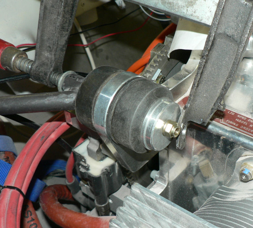
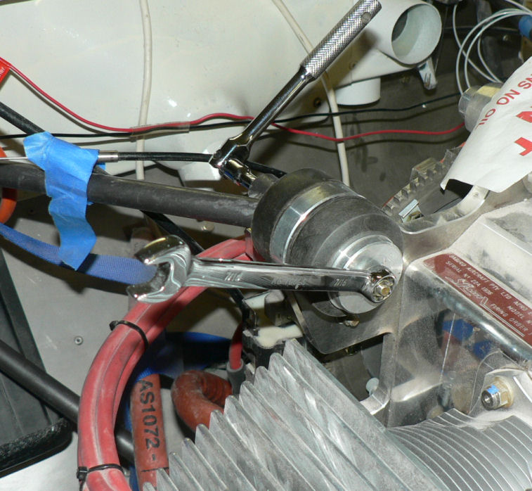
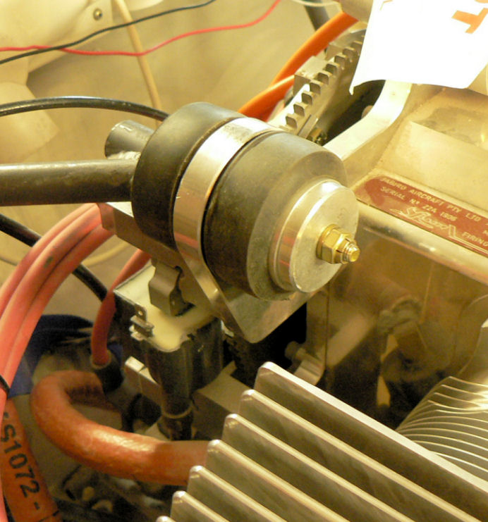
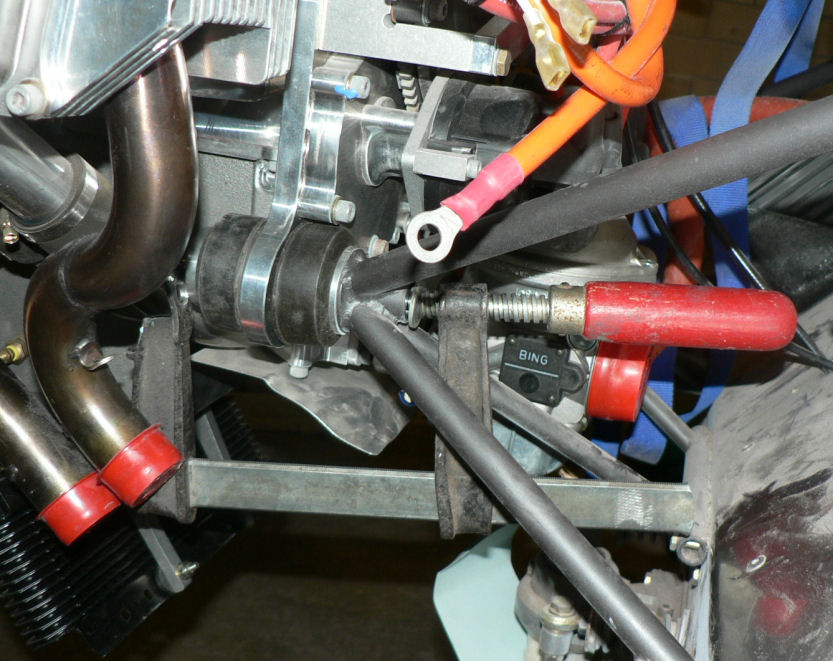
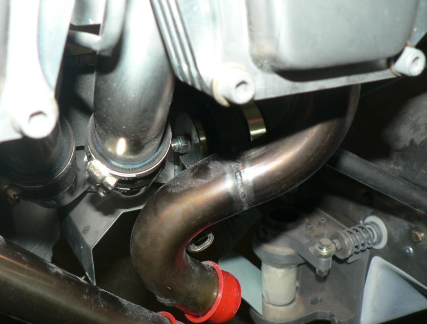
17-10-2007 Had another look at the engine mounting bolts and the construction book- decided I had the bolts in the wrong way and should have had heat proof nuts on them. Rectified that. From the pics you can see that the clamp I am using to compress the engine mount rubbers could be modified so that the socket spanner will fit through a hole at the non screw side of the clamp so that the clamp could be kept straight while pulling it up. I will have to braze or weld a slightly thicker piece of steel on that end with a hole in it big enough for the socket and washer to fit through. Attached the oil overflow reservoir and fitted the hoses - still need a clamp underneath to locate the overflow hose. Sat the air ducting on top of the engine cylinders - need to be reinforeced at the join with a couple of layers of glass. Wiil do that once it all looks ok. Need to set up the spinner backing plate, spinner flange and aluminium backing plate & propeller so that the spinner can be fitted and then the Cowls can be fitted to match the propeller boss.