Ross
-
Posts
729 -
Joined
-
Last visited
Content Type
Profiles
Forums
Gallery
Downloads
Blogs
Events
Store
Aircraft
Resources
Tutorials
Articles
Classifieds
Movies
Books
Community Map
Quizzes
Videos Directory
Everything posted by Ross
-
I vaguely remember a story written by a Canadian pilot who usually started her day and eventually her aircraft by placing a large oil burning space heater under the nose of her aircraft in the hanger until it was thoroughly warmed up. For that particular day, the flight described was very short and disastrous. If a heat source like a paint stripper or a fan heater were to be used, I would suggest it be underneath the engine where the air when cruising usually comes out. The fan heater or paint stripper could even be sitting on the floor as long as the rising hot air got into the engine compartment. I have also heard, second hand, of early 2.2 Jabiru motors with inadequate batteries or the smaller starter motors being pre-warmed by having a jug full of boiling water poured over their cylinder barrels of what you can see. Maybe you could take a large thermos flask of hot water for the motor for the morning starts. Jabiru have recommendations for different oil grade for colder weather as I would assume the other engine manufacturers also would do. Regards
-
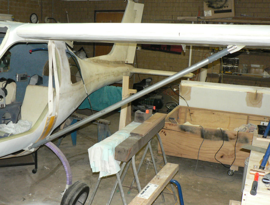
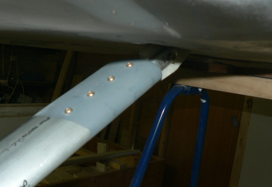
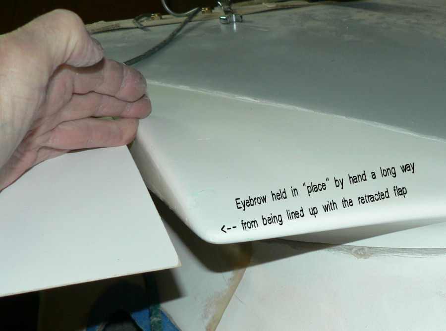
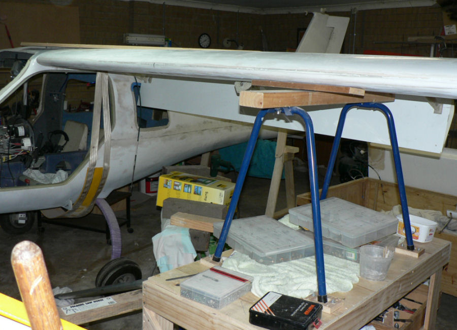
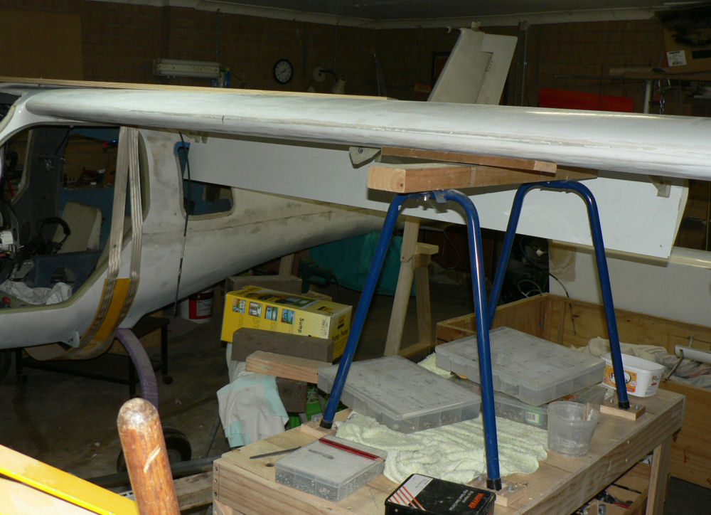
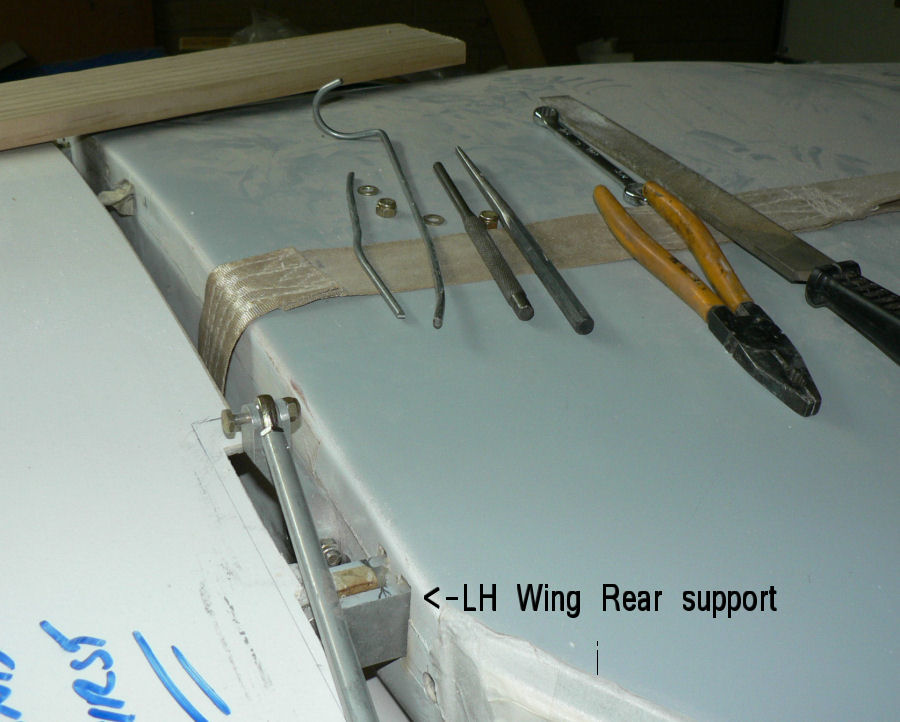
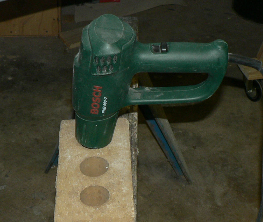
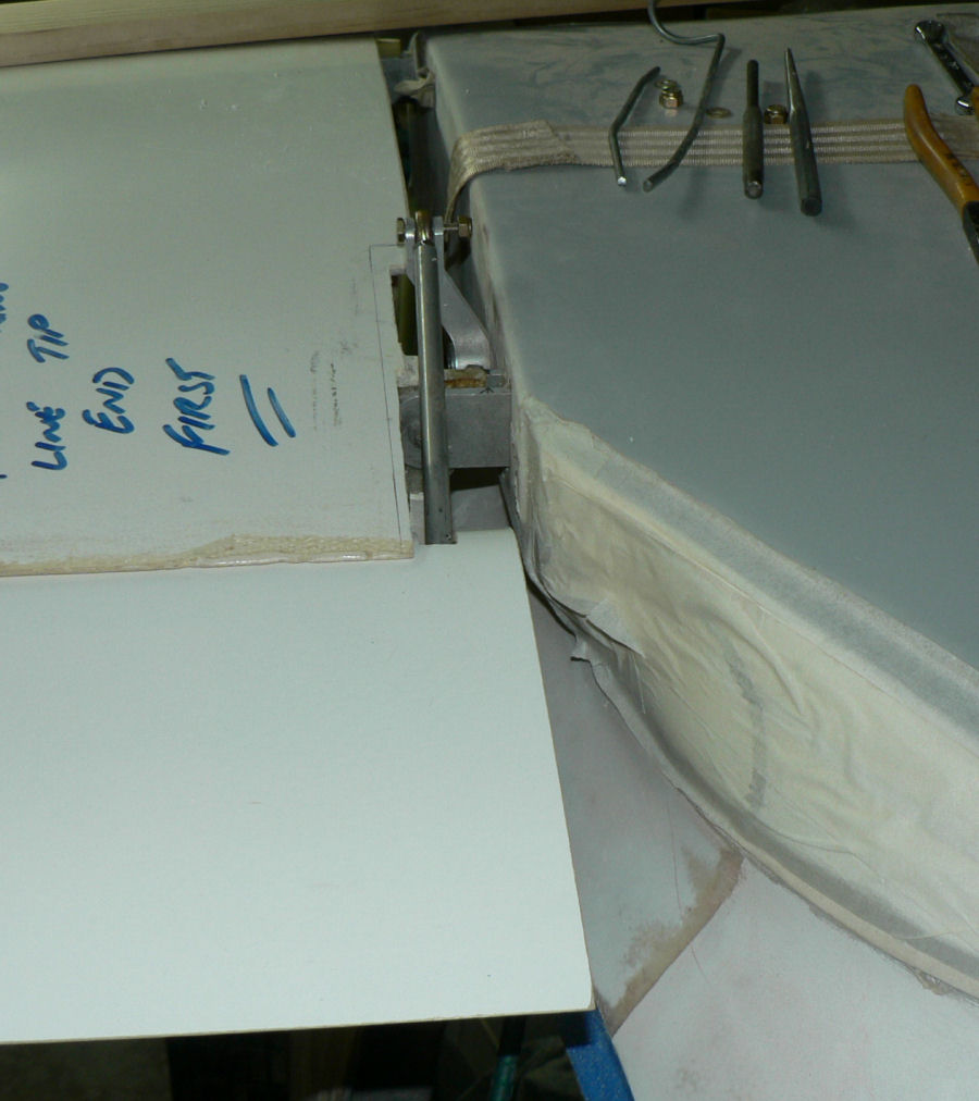
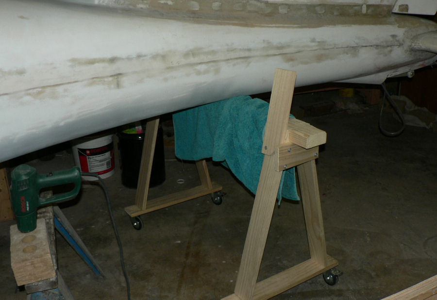
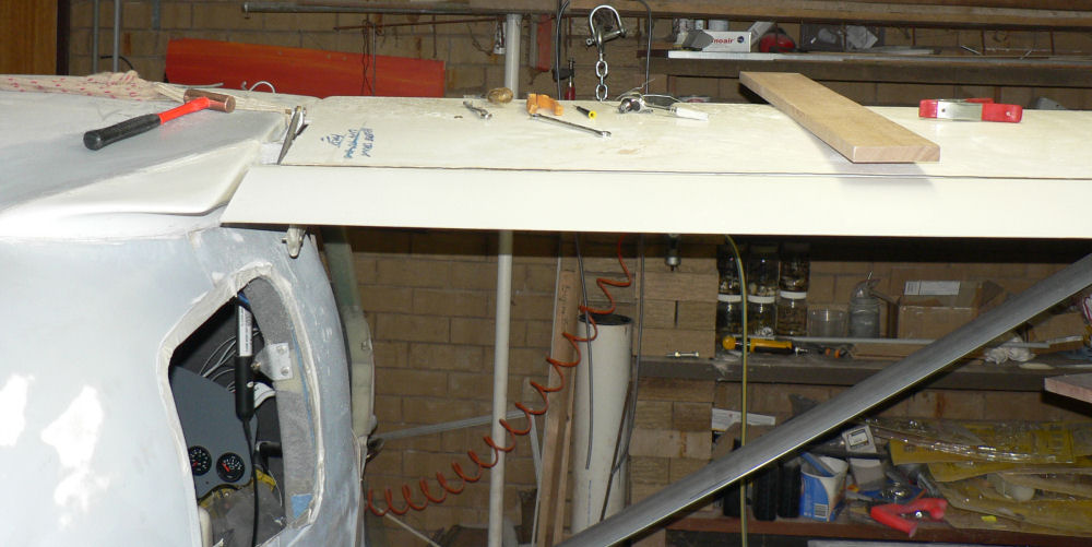
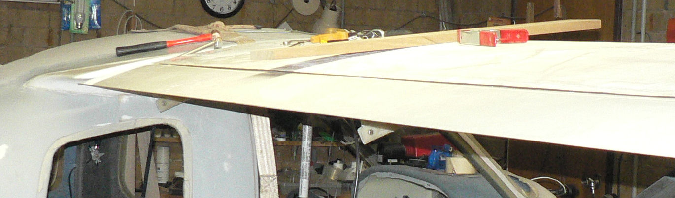
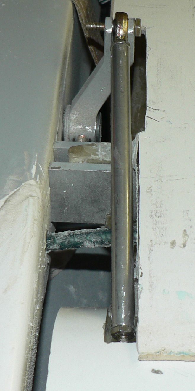
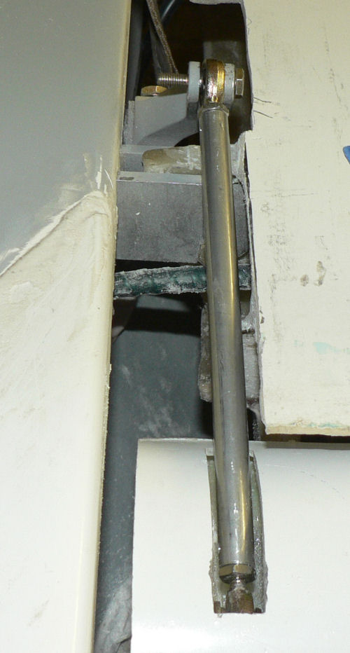
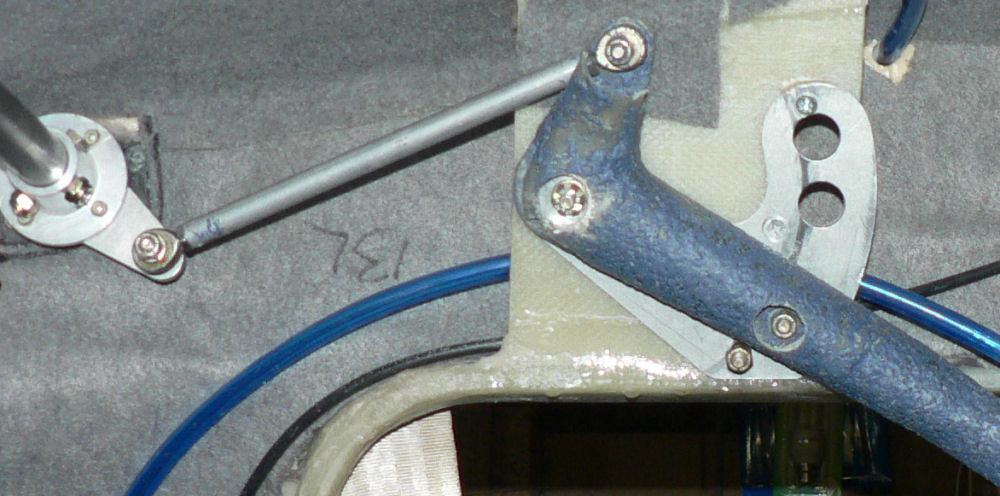
30-08-2007 Started off with the wing already attached to the a/c at the inner end of the wing and the outer end supported on a trestle on top of the moving bench. This made it easy to lever the wing up or down to match the strut holes. [ATTACH]3423.vB[/ATTACH][ATTACH]3422.vB[/ATTACH][ATTACH]3424.vB[/ATTACH] Mounted LH wing strut with strut end bolts put on top & nuts underneath. Had to rub down the NAS6605 19 0010 bolts to get them to match the fittings on the end of the strut and the SS lugs under the wing and on the underside of the cabin. Sanded some material off the lugs so that the strut ends would fit over the fibreglass lugs & SS bushes. Sanded a radius on the lug edges facing the strut to match the slot in the strut ends otherwise the strut would be deformed when bolted up at both ends. After getting the bolts to match the fittings then bolted up one end of the strut. Then heated that end SS bush and surrounding area and manipulated it so that the other end of the strut lined up with the other lug. Once it stayed lined up, then removed the bolt from the first lug. Fitted the second bolt to the other end of the strut and repeated the procedure above for the SS bush and lug at this end. Once the strut was lined up for the second time, refitted the first bolt. This can result in some binding of possibly both bolts again but at least they are in without breaking any thing. So then heated both SS bushes again to ensure that bolts were not binding when both ends of the strut were bolted up and attached to the wing & underside of the cabin respectively. So now at either end of the strut the bolt can be moved or removed relatively easily without any noticeable binding. This gave the heat gun a workout taking care not to apply enough heat to char or burn the fibreglass. The heat gun was used on a low setting and surprisingly only took a couple of minutes to make the material very pliable! A small piece of sheet metal was used to deflect most of the hot air from entering the wing via the space around the under wing lug. As you can see in the third photo, there is a problem with the alignment of the flap with the "eyebrow" which is not attached yet. The starboard eyebrow, attached to the fuselage before the wing & flap were mounted is similarly misaligned at this stage!

-
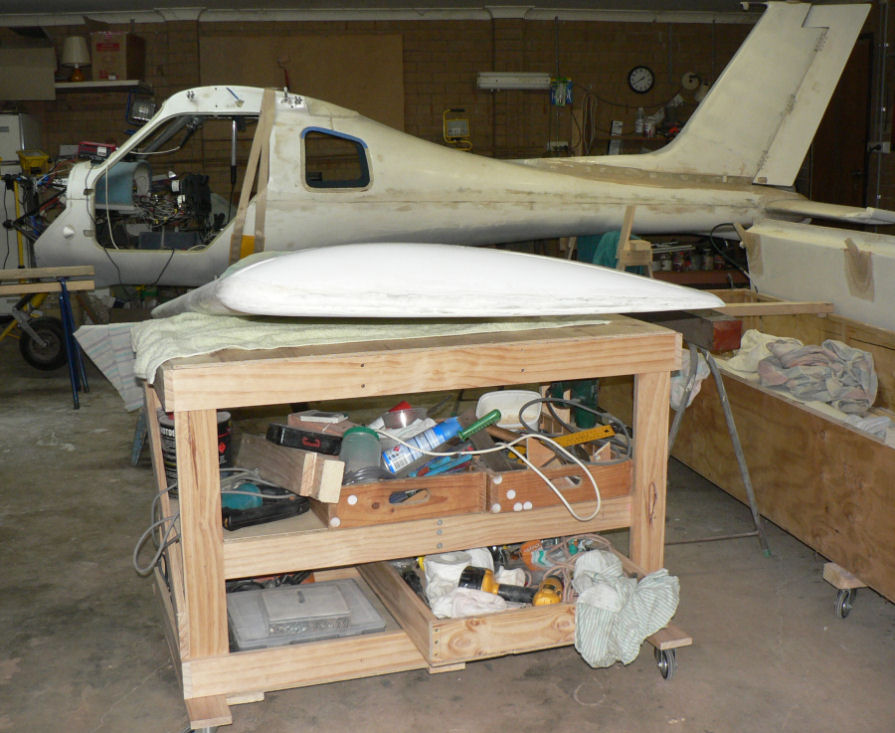
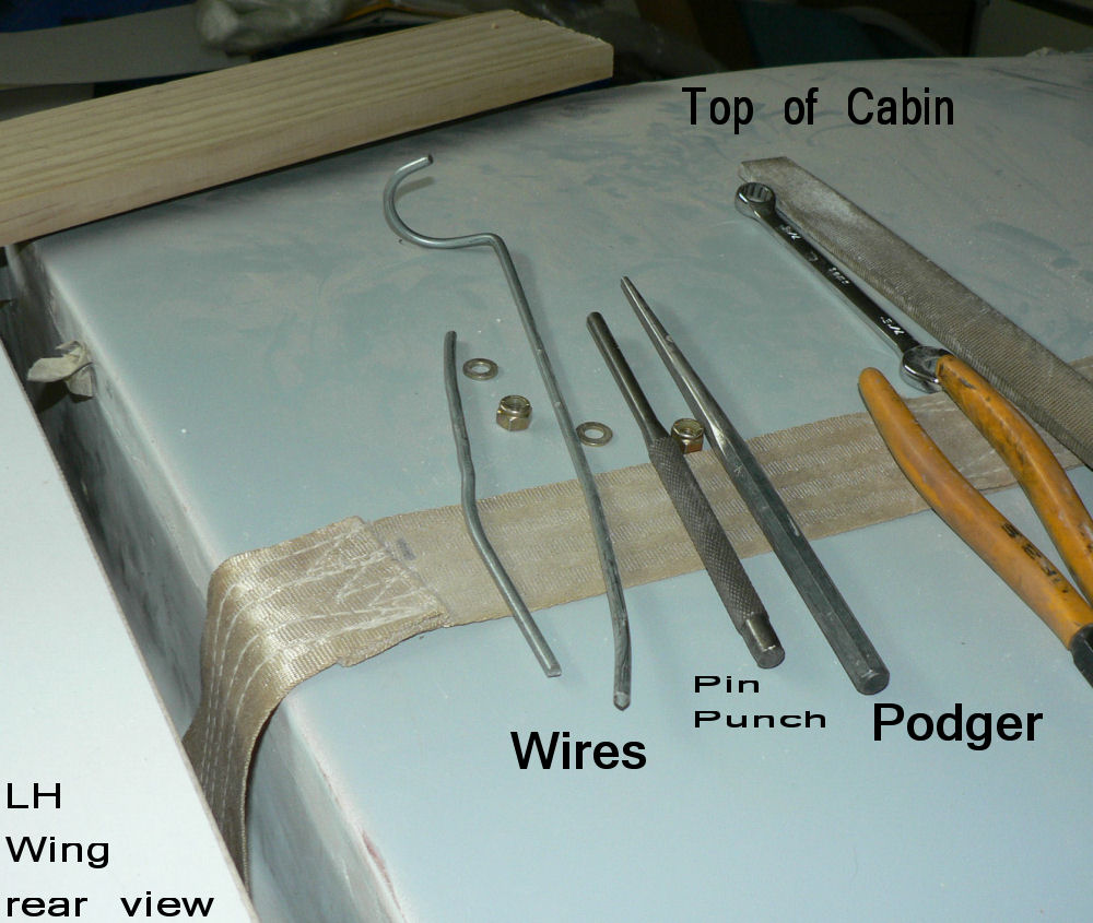
28-08-2007 Put shelves in castor wheel bench. Put most commonly used tools under the bench together with fasteners. Turned A/C around in garage ready for mounting Port wing. [ATTACH]3406.vB[/ATTACH] Trimmed the the top inboard end of the LH wing to make clearance for the flap actuating rod. Sat LH wing on moveable bench near the balance point and trestle etc on inboard end to raise it close to the height of the mounting points on the cabin. [ATTACH]3408.vB[/ATTACH][ATTACH]3407.vB[/ATTACH] The top inboard wing attachment bolts were tried in their positions and found to be too tight. So they were polished down to fit the lugs on the wings and the cabin. Used bent wires in the photo instead of bolts to make the initial connection between the wing lugs and the cabin lugs. Next replace one of the wires with the podger (tapered punch) to get a closer alignment. Then replace the other wire with an AN174-14A bolt and may have to loosen or remove the podger to allow the bolt to line up with the wing SS bush hole and the cabin lugs. As the alignment of the SS bush in the fibreglass lug on the wing was a bit off at this stage I stopped trying to attach the wing. I then heated this SS bush in the wing lug and continued the attachment. [ATTACH]3410.vB[/ATTACH][ATTACH]3411.vB[/ATTACH] Each bolt may have to be inserted in its heated SS bush with the other bolt not inserted. Once the bolt is inserted, the wing can be pulled around to line up the other bolt holes if neceassary and the podger inserted to hold the position until the bush and fibreglass cools down to hold the bush in alignment. Once the first bolt is in & the bush set in an aligned position remove the bolt and heat up the other bush and get its bolt inserted. Once the second bolt is in push the wing around to line up the other holes and then insert the first bolt again. Allow the second bolt & bush to cool down now that all is aligned for that top inboard wing connection. Both bolts were checked for ease of removal and insertion. If they were still too tight they could be improved by application of more heat to the SS bushes and the reassembling the connection. Fitted the flap and ensured there was clearance for the flap rod - unfortunately am short an AN3-14A to make the final connection to the flap. [ATTACH]3413.vB[/ATTACH][ATTACH]3409.vB[/ATTACH] A similar procedure will happen for the LH wing strut.
-
27-08-2007 Made up saw horse type support with castor wheels for moving the a/c when engine not mounted. [ATTACH]3412.vB[/ATTACH]
-
Hi Geoff Getting there! But the security guy is getting greyer around the gills! Regards
-
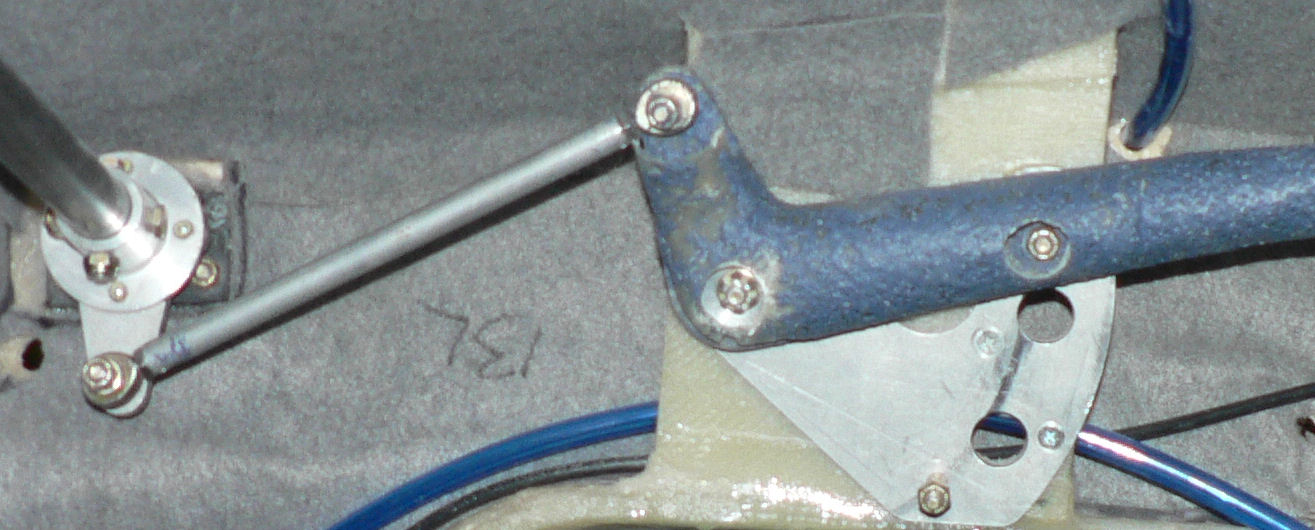
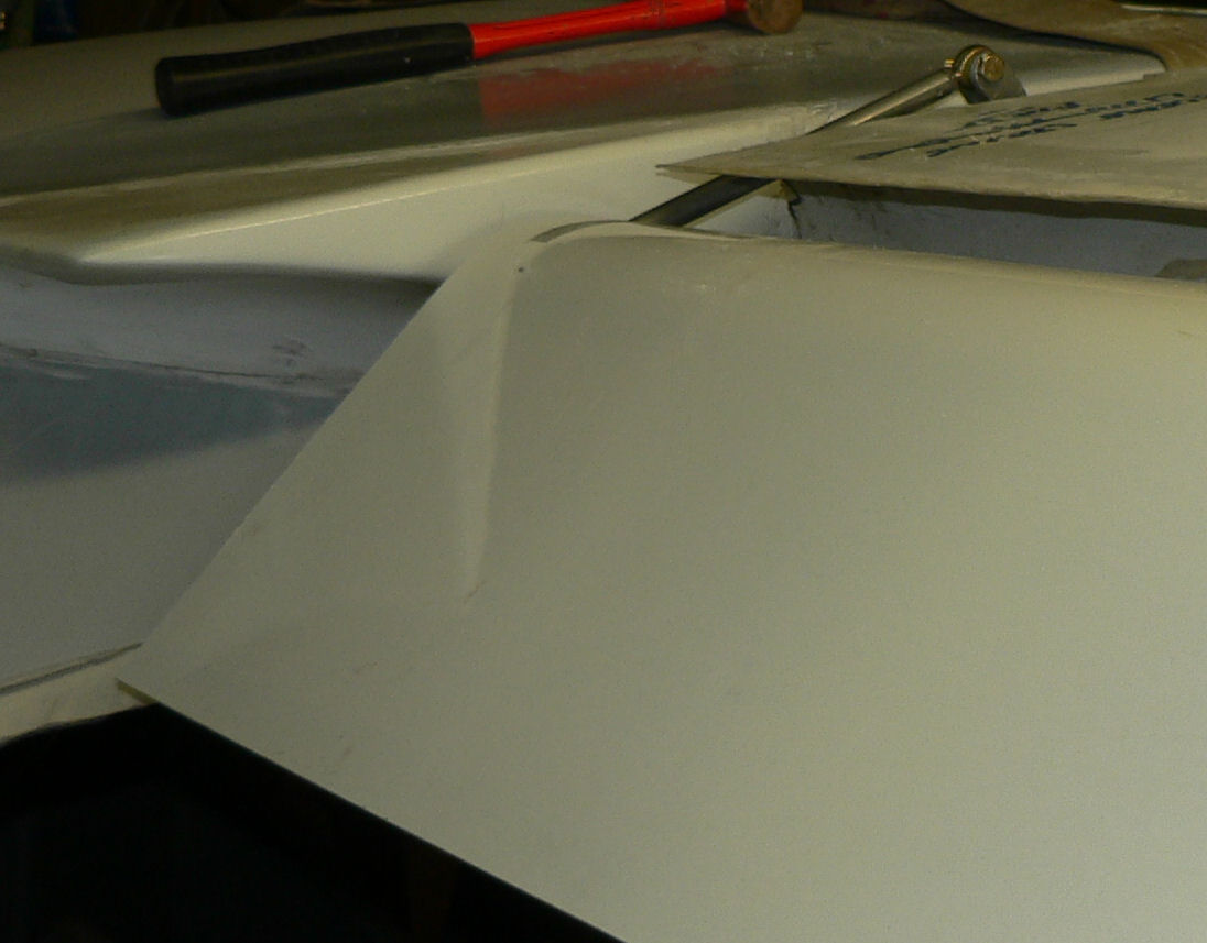
Wings continuued 24-08-2007 Fit flap to RH wing on A/C. Connect up flap lever system to flaps. Check flap rods for clearance on top of inboard end of wing and adjusted as necessary. Flap actuating rod between flap handle and flap cross over shaft shortened about 10 mm so that flap lever can be put in neutral position when the flap is connected. A flat edge under the wing from leading edge of wing to trailing edge of flap should have 4 mm gap near the junction of the flap & wing when the flap is in neutral position. In these photos it is close to that position in the "flap up photos". Photos around RH wing & flap in up & fully deployed positions. [ATTACH]3354.vB[/ATTACH][ATTACH]3355.vB[/ATTACH][ATTACH]3356.vB[/ATTACH][ATTACH]3357.vB[/ATTACH] Flap up photos [ATTACH]3360.vB[/ATTACH] [ATTACH]3358.vB[/ATTACH][ATTACH]3359.vB[/ATTACH] Flap down - deployed photos As pointed out by Geoff Waddleton I should not have fitted the eyebrows on the fuse abeam of the flap position until the flaps are fitted and set in their correct position. I have only done one so far & I kept it in line with the top of the wing but it is the flap that it should line up with so a bit of radical adjustment is needed here. 23-08-2007 Fit RH wing to AC 22-08-2007 Build castoring table to support wings during connection of wing to aircraft. 20-08-2007 Clean up microball fill on wings Check & mark position for stall warning on port wing and drill hole inboard end for air hose to stall warning horn very carefully as there is a danger of drilling into fuel tank. Check position of fuel tank before drilling. 10-08-2007, 11-08-2007 A couple more sessions done on filling rough areas of wing tips mainly with microballs.
-
Reinstalling Jab tyres Hi Crew Having heard of some Jab tubes being pinched by the split rims as they are being fitted (not on this forum) I applied a few of my fathers lessons to tyre fitting on my J160 kit. Applied some Johnsons baby powder in the tyre before inserting the tube so that it will not stick to the tyre (hope no water gets in there). After inserting the tube into the tyre before fitting and bolting up the rims, I put sufficient air in the tube to maintain a round shape so that it cannot be pinched by the rims when they are pulled together by the bolts. Now I will just have to do it all again if and when I get some 10 ply tyres to replace the 6"x6 plys. From what I have heard even certified Jabs would be well advised to check the alignment of their mains. Regards
-
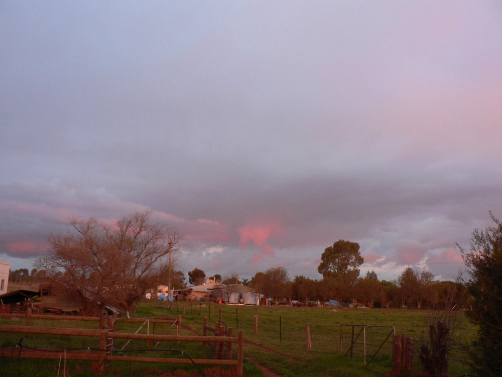
Hi Crew A strange weather day today with a strange mass of unstable air floating around from Narrandera to Leeton with only Narrandera and Yanco reporting any rain, 0.4 and 1.4 mm respectively, within 100 miles or more. Brobenah airstrip would have got a few more mm late in the morning. Photos taken on sunset with very light rain and a light rainbow on the east side over the Brobenah hills near the airstrip and a classic sunset on the west side. All photos taken in about a five minute time span. The fourth photo has some birds heading for the river at last light approx south west of our house - probably well over the middle of Leeton at that stage. [ATTACH]3321.vB[/ATTACH][ATTACH]3324.vB[/ATTACH][ATTACH]3325.vB[/ATTACH][ATTACH]3326.vB[/ATTACH][ATTACH]3322.vB[/ATTACH][ATTACH]3323.vB[/ATTACH] Regards
-
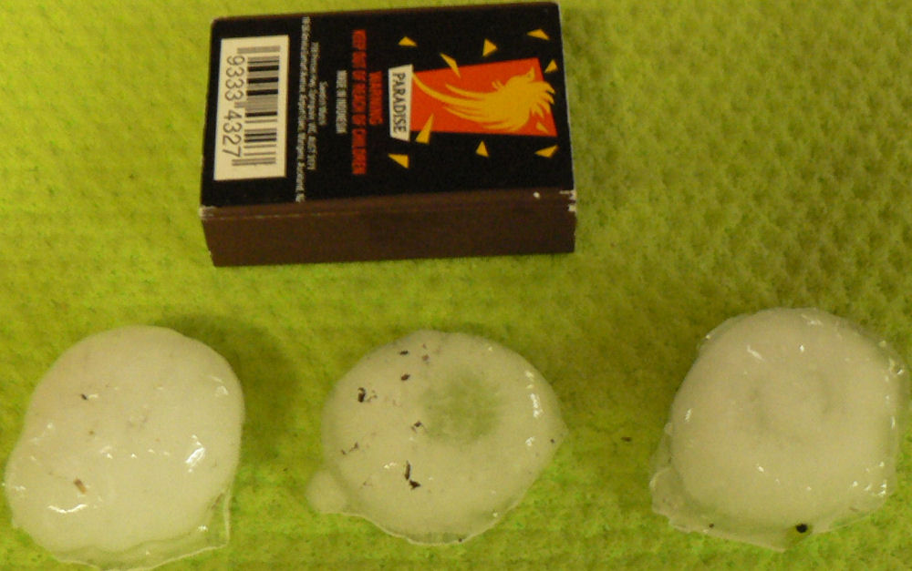
Hi Ben As you can see from the photo these were well over 3/4" and not a regular sphere shape. I think the thing that saved us was that they were distinctly doughnut shaped. I have never seen hail that shape before. That probably reduced their terminal velocity. They were certainly making a hell of a din on our concrete tiled roof, on our outside gauzed in area with a metal roof and also when they hit the car roof and windscreen. Regards
-
Hi All We had a bit of HARD weather arrived on Thursday night. It lasted on and off for about half an hour a looked a bit like a doughnut with the middle just filled in. It showed about 6 mm in the gauge even though Yanco only recorded 4 mm. The photo shows three pieces that had started to melt before I put them in the fridge so they had lost most of their distinctive doughnut shape by the time I photographed them today. [ATTACH]3313.vB[/ATTACH] I thought our car would be damaged but it appears to be none the worse - we chucked a sheet over the roof of the car part way through the storm. The Jab is in the garage. Regards
-
I have no more to add for the detail re the M760 upgrades. In Microair's reply this morning to my last email, they did not answer any of my questions. Were they, the questions, too dumb - most of the queries on capability can be answered by reading the User Manual for the latest version but not any detail about the integration updating older gear. The PDF combined Installation and User Manual can be downloaded from the Microair website as a PDF file and printed out at your leisure. It is 28 pages long at this time. Regards
-
Hi brentc As you can see I have just re-entered my AVTAR which is still earthbound indicating that my J160 is still very much in the garage. The solution to my problem as my younger brother told me at the time near kit purchase was not to buy anything for the kit that I did not need at the time - the trouble with introductory pricing. I now have half a dozen reasons to regret that decision! You make a very compelling argument to have a second radio not dependent on the aircraft radio system and also the ability to vary the volume of either/both and not have traffic for the primary frequency cut off the secondary radio message. My experience is limited to one radio monitoring a single frequency in an area with relatively light radio traffic with maybe a maximum of six airborne around the airfield at once and that would be unusual. I certainly noticed the problem of changing non stored frequencies on a trip from Griffith to Albury and especially in RAA height bands which are always going to be less than the top of the CTAF above any airstrips you go near. An RAA aircraft is highly likely to be in a height band where other A/C are likely to be descending to land on a nearby airfield so a need to monitor the area frequency and the nearest CTAF or even maybe more than one CTAF?? Anyway I suppose I got off the subject - I was really only trying to sort out the options for upgrading that were available from Microair and what they would cost (being a major point as far as I am concerned)!
-
M760 Transceiver - Available UPGRADES After spending most of the day on this I suggest that anyone wanting more information on the subject ask Microair to email them a PDF file of the "M760 TRANSCEIVER - AVAILABLE UPGRADES". Then ask them to explain it in detail and mention what equipment you have already installed. If I understand it correctly the latest brand new $1320 M760 Rev P Transceiver is available provided that a working (as determined by Microair) older model M760 transceiver with eligible serial number and Rev numbers is available for exchange for a net price of $880 Australian dollars including GST - freight is not mentioned so far. These prices today are list prices not quotes. It is not clear to me from the PDF "M760 - Available Upgrades" file what in addition I am up for in $$ for the Jabiru where I already own an older M760 Rev N serial number 760-008089 transceiver plus a PM501 intercom and wiring harness. It is starting to be an expensive radio but the ability to monitor two frequencies at once, plus store 99 labelled frequencies probably makes it substantially cheaper than buying an additional radio and intercom and integrating it with an existing radio. The new Rev P also addresses a number of stability, interference, quality and tuning issues of the older Rev N model according to their handout and includes a built in intercom if I understand the user manual correctly - check this as I am not sure of that last item.
-
Rev P upgrade for the Microair M760 Rev N Transceiver Hi Peter I contacted Microair on 8-08-2007. They sent me a quote for two types of upgrades to the old Rev N of the M760 Microair Radio without a full explanation of the implications of either upgrade or the differences between them. Although some idea can be obtained by going to their web site and looking at the PDF files available there which are for the latest version of the radio, the Rev P version. One of those http://www.microair.com.au/admin/uploads/documents/p45radio.jpg is the data sheet and for the Microair M760 Rev P Transceiver another is http://www.microair.com.au/admin/uploads/documents/M760PInstallUserManual01R5.pdf is the Install and User manual for the latest version of the Microair M760 Rev P Transceiver. the third one is a wiring diagram for the Rev P http://www.microair.com.au/admin/uploads/documents/760RevPwiringdiagramstandardinstallation1.pdf They gave quotes for two upgrade options and I have used their words below verbatim! Option 1 M760 rev N upgrades FM/Heat/ANL/Mic & 108 tuning $220 Freight Domestic $15 Option 2 M760 Rev N upgrades to Rev P which includes above upgrades $660 Freight Domestic $15 Add GST to each quote above. According to the user manual above, which is very comprehensive, the Rev P model addresses a number of limitations of the older Rev N model which make the later Rev P very attractive by comparison. A few of the new features that I noted (there are many more): Ability to store 99 frequencies compared to 25. Ability to show and store Alpha numeric chars for each frequency stored which display as they receive transmissions (this would be a big help when checking and updating stored frequencies); Ability to monitor two frequencies microseconds apart; (Could monitor area frequency and CTAF practically simultaneously) Ability to monitor ATIS weather channel w/o risk of accidently transmitting on that frequency. Can set an option so that you cannot transmit over the top of an incoming signal on the same frequency; Displays a flashing light if a transmission lasts longer than either 30 or 45 seconds (don't remember which) to pick up stuck PTT buttons. I shall have to contact them to differentiate between Option 1 and Option 2. Regards
-
Greetings to the Kit Fox IV driver when he gets around to putting his name up here. Regards
-
Hi Ian I am going to be away from my computer for a week or so and I will possibly miss the big 1,000 member target event that is likely to occur in the next week or two. :confused: If so congratulations for achieving it when it does arrive. ;) I hope that it is starting to pay you some rewards for all your effort and the innovative ideas that you are introducing to make the site more diversified and interesting to a greater cross-section of people and I thank you for your moderating influence on the site. Regards
-
This one is from Canada and is labelled Painted ceiling in a smoking area
-
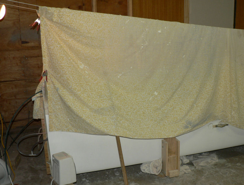
16-07-2007 I have an excuse visitors for the last two days. Were going to have a fly at Narrandera on Sunday afternoon but Wally had an early nav ex planned for a student and the fog did not lift till about 12:00 so that moved my 15:00 time slot to never never land!:confused: Doing more cleaning up on RH & LH wing. On the RH wing the trailing edge on the RH wing in the flap area had not filled completely between the two layers of fibreglass. So I sanded off the bottom layer to make the edge more tapered and then filled it with epoxied microballs which is very easy to dress with any tool. Draw strings reborn[ATTACH]2598[/ATTACH] Nice & warm under the sheet [ATTACH]2599[/ATTACH] Garage temp this morning was 8.6 degrees C. Max outside Sunday 8 degrees, min 3 degrees
-
Hi Ralph My J160 kit#14 is yet to fly but it has engine number 22A 1906 so it is in the middle of all the oil cooler and oil pump changes that were made or recommended by Jabiru. It does not have hydraulic tappets which came out a little later on with its own set of modifications then there are the engine, carburettor and jet changes that were also made let alone the changes to the fuselage mostly minor (that I know of) in the cabin and control arrangement. So as you point out when talking of these engines it is very important to nominate the engine number and whether the mods are all installed. Regards
-
My copy of "Ultralight Basic Aeronautical Knowledge" by Des Rycroft has some information on "Flight Rules & Procedures" on pages 71 through to 78. One of the points amongst others is on "Entering the circuit Circuit entry is by flying at least three legs, i.e. all or part of downwind, base and final. Entry height is usually 1500 feet AGL and circuit height usually 1000 feet AGL ......" Are we still bound by these "Ultralight" rules although I know they have been modified to some extent with a least three circuit heights now in force plus the different climb out height before turning cross wind and the local requirements for fly friendly at various strips as listed in ERSA? Regards
-
11->12-07-2007 Work continues on RH & LH wing leading edges with some scraping, sanding & minor filling to match the updated template with the emphasis on the radius of the leading edges. Some minor filling using micro-balls was done on both wings. Two of the retained nuts that secure the aileron hinges were moved to make them more effective. The heat gun was used to soften the epoxy around the retained nuts making their removal fairly simple once the rivets were drilled out. The clearance between the aileron plate on the RH wing and the aileron was set to the correct clearance. I also found the heat gun effective in improving the alignment of riveted and epoxied hinges in assemblies like wing mounted ailerons. It is achieved by heating them to soften the epoxy and allowing it to relieve stresses by achieving a better alignment of the hinges while soft and retaining that alignment once it cools. Freeing up of tight hinges is a matter of maybe two or three minutes work by using the hot air gun. Take care not to burn the epoxy or fibreglass . It does not indicate its softness by a colour change. So it is quite soft long before the epoxy starts to char or go brown then black. I am yet to return to the elevator hinges which are probably acceptable being quite easy to move and do not stick in any position. Their movement could be a little more free by application of some heat to the hinges. More clean up is needed on both wings to clean up the filling and modification done over the last two days. None of the epoxy work is being helped by minimum temps overnight of 0 degrees C outside, about 10 degrees C in the garage and maximums of about 11 degrees C outside and lower predicted tomorrow. I think I will have to take advantage of the big high pressure system that will be sitting over this area on Sunday afternoon and relieve some pressure by applying some aerial therapy for an hour or so out of Narrandera.
-
Some years ago at Brobenah Airfield (Leeton) during a Gliding comp I saw a large cardboard box take off vertically and disappear vertically into the blue sky. Regards
-
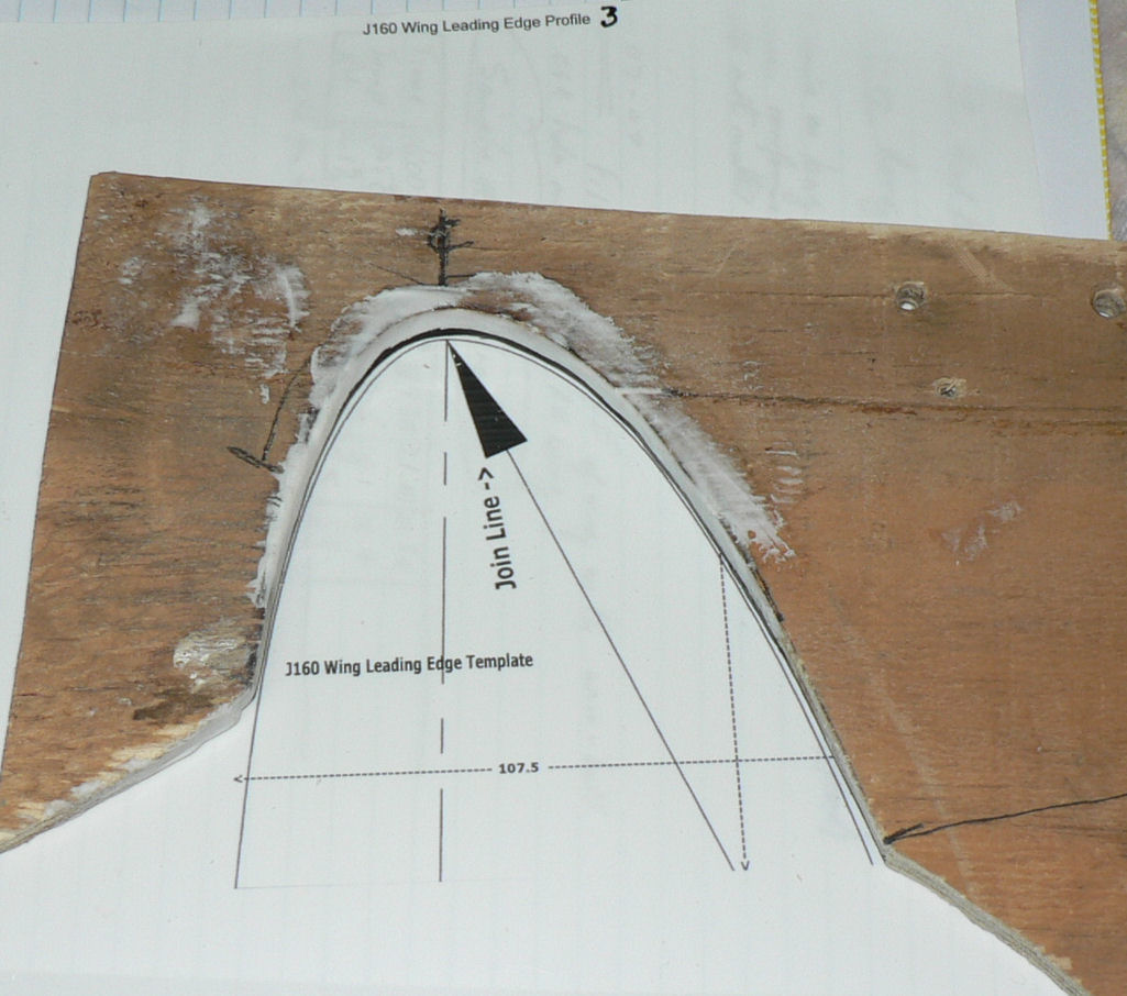
9-07-2007 Applied thin layer of epoxied micro-balls to leading edge of LH wing for whole length. Near the wing tip end for about 150 mm length is very flat instead of having the nice curve as per the template. It is now cured enough to check and it will need at least another layer tomorrow (later today) at that point probably about three or four mm over a short length. I also filled in the csk holes on the RH wing aileron plate using epoxied micro-balls. Have also applied some epoxied micro-balls to the wing template before filing it to match the drawing derived from the Jabiru PDF file. Photo shows the template during filing to match the drawing. Very hard to photograph so I drew on the bottom edge of the template with a black marker pen. It looks better from vertically above it - the important perspective but I cannot get a representative photo from above. [ATTACH]2575[/ATTACH]
-
9-07-2007 See results of Phone call to Rod Stiff, managing director of Jabiru, added to saturday's post below. Regards
-
Hi Mazda Mine came from RAA a couple of months after I applied for it in 2006 without any handy cover or folder or lanyard. I eventually found a foldable "pension card holder" this year in my local paper shop that can allow it to be displayed by clipping it over a pocket with the smallest spring loaded paper clip that I could find there but the picture is then displayed in landscape mode rather than standing up in portrait style. [ATTACH]2564[/ATTACH] I am not impressed with a card on a lanyard around my neck that could get entangled in items during an extreme situation and result in strangulation or drowning or getting trapped in a fire. Regards