Ross
-
Posts
729 -
Joined
-
Last visited
Content Type
Profiles
Forums
Gallery
Downloads
Blogs
Events
Store
Aircraft
Resources
Tutorials
Articles
Classifieds
Movies
Books
Community Map
Quizzes
Videos Directory
Everything posted by Ross
-
Hi Darren It occurs to me that it could also indicate that an engine has lost some performance and that a normal idle setting is not enough throttle (power) to keep the motor turning over, not necessarily so in your case but a possibility or a bit of both. I think Jabs are supposed to be set to idle at about 800 RPM but some people set them a bit higher to get smoother engine running which could make the choke not effective and could hide the engine stall that would or possibly occur as the engine performance drops off due to normal or otherwise wear and tear. Regards
-
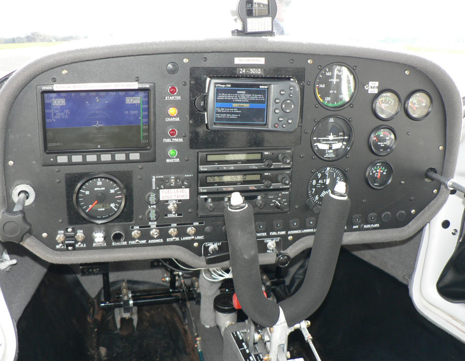
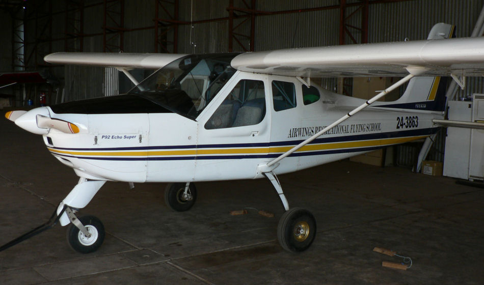
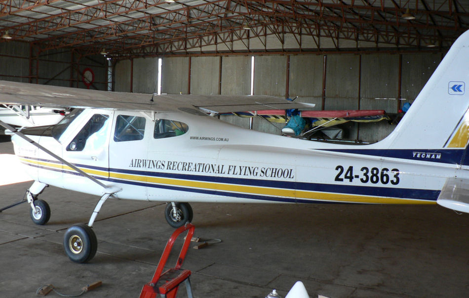
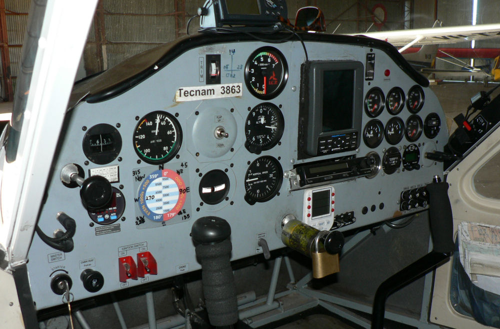
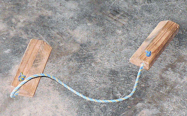
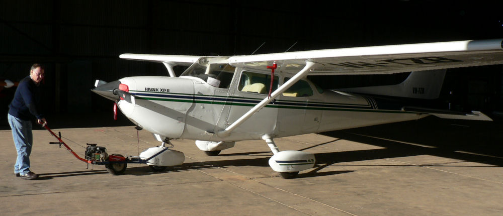
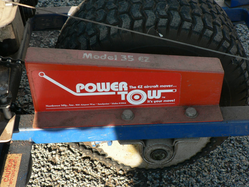
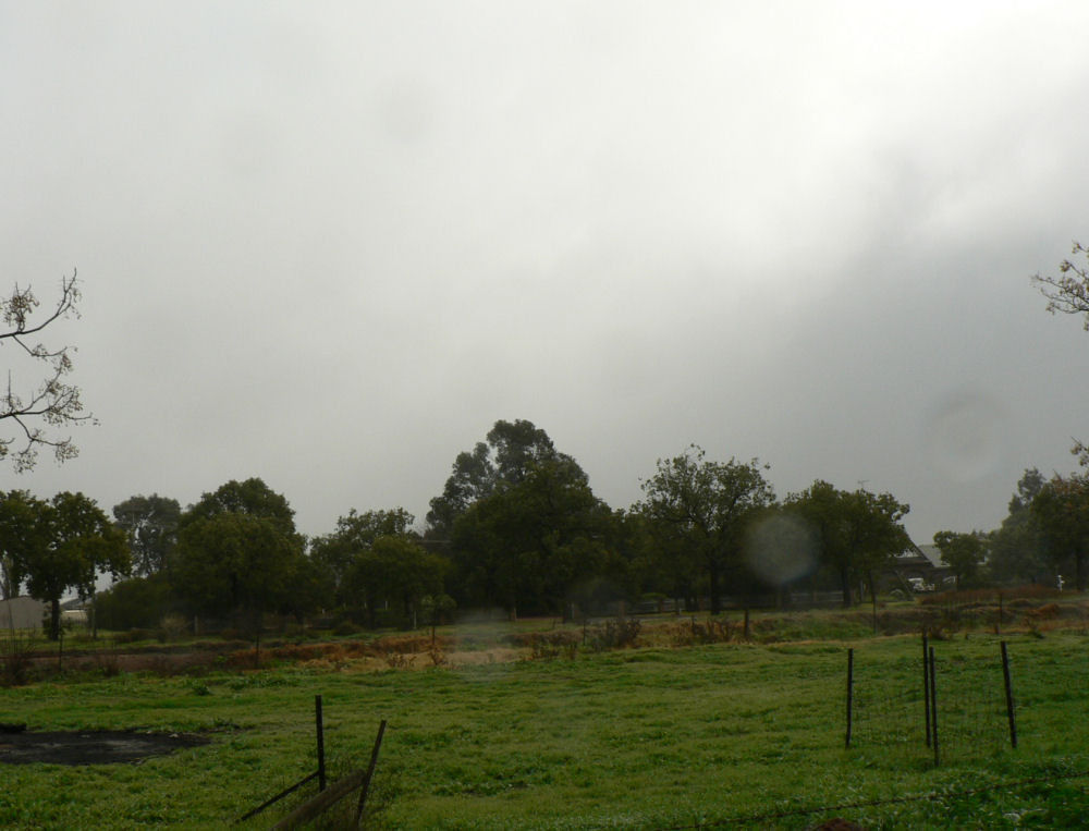
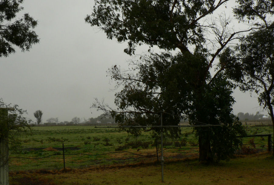
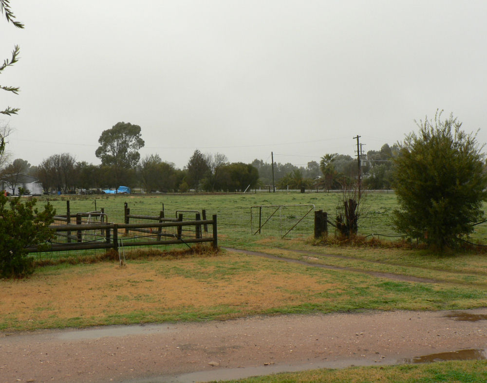
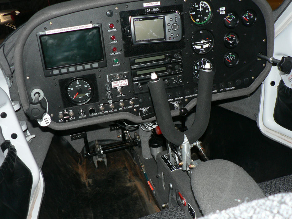
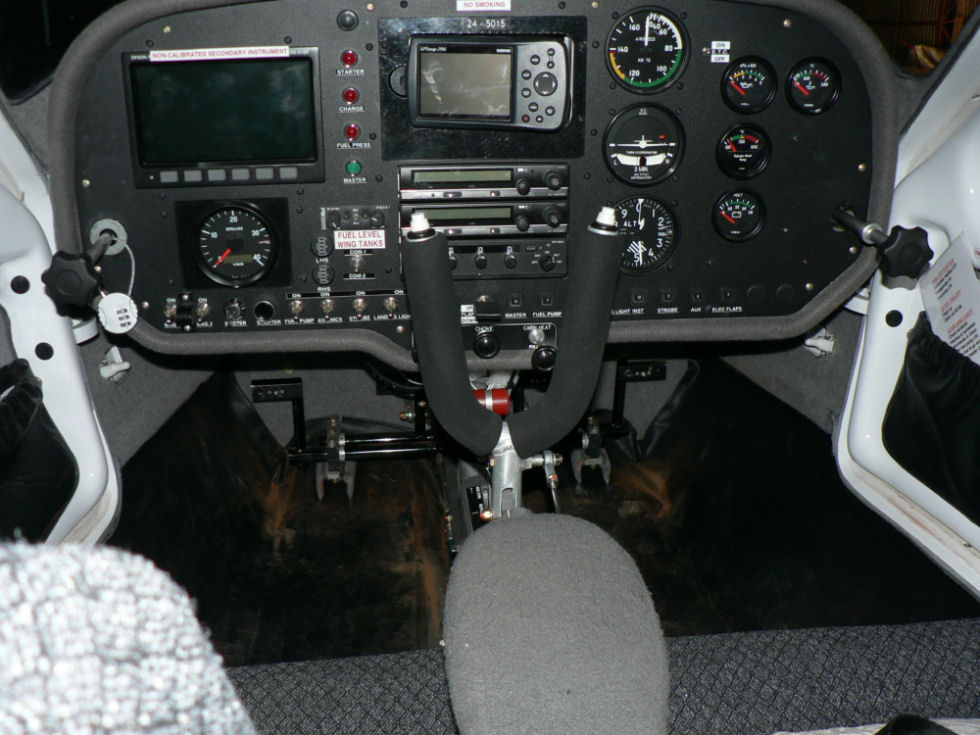
8-07-2007 Today at Leeton the rain gauge had about 4 mm in it from last night and the cloud base at Leeton was at about 600 AGL at 11:00. I gave Wally at Narrandera a ring and decided to go to YNAR. As I drove in the gate at Narrandera AD Wally was about 10 m in front of me. We sat for a while in the MAC Club house with the cloud base still pretty low maybe 800 feet AGL but showing signs of improvement. Steve? arrived with the barbecue meat (every 2nd Sunday of the month) plus Roger, one of his syndicate Jab 230 mates, and they had a fly in their AC. A few others turned up as well as the CTSW from Wagga. Wally took me up again in the J230C for my second flight in it and got out after half an hour or so and left me to it. I did two more circuits solo and as the windsock was starting to get that iron bar look across the strip decided discretion was the better part of valour and returned to the terminal area. The gravel cross strip was too wet from the rain over the last few days and the REX RPT was soon due. The cloud base was about 2,000 ft AMSL during my flights (lots of carby heat). I took a few photos of Wally's Jab 230C with power on the panel plus a couple of shots of his Tecnam P92 & panel plus another AC in the hanger and the neat tool for dragging it around. I think they paid $US700 for it a few years ago. The J230C engine choke control and electric flap control are both hidden behind the PIC's forky stick. J230C Panel[ATTACH]2556[/ATTACH][ATTACH]2557[/ATTACH][ATTACH]2558[/ATTACH]Tecnam Panel[ATTACH]2559[/ATTACH] Tecnam Chocks [ATTACH]2560[/ATTACH]Handy Gear [ATTACH]2561[/ATTACH][ATTACH]2562[/ATTACH][ATTACH]2563[/ATTACH] The handy gear has forward & reverse gear plus engage disengage the hookup all from the T handle. It has a petrol (according to the owner ULP or AVgas?) powered rope start Briggs & Stratton motor.

-
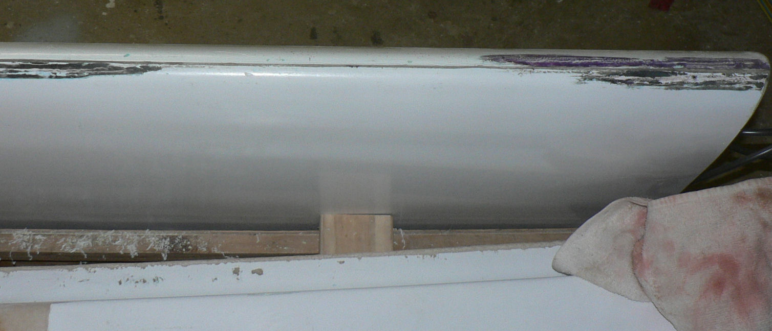
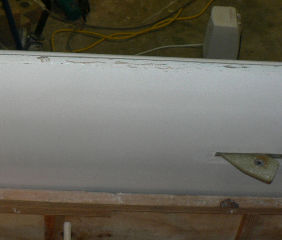
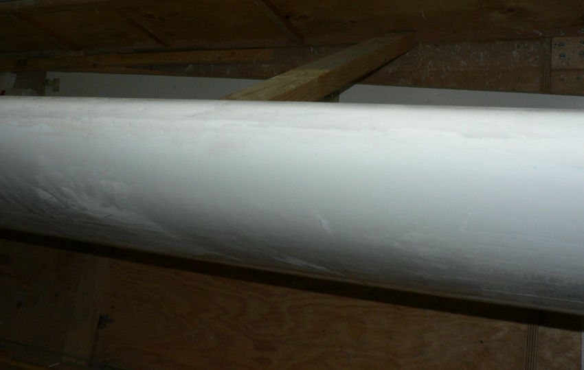
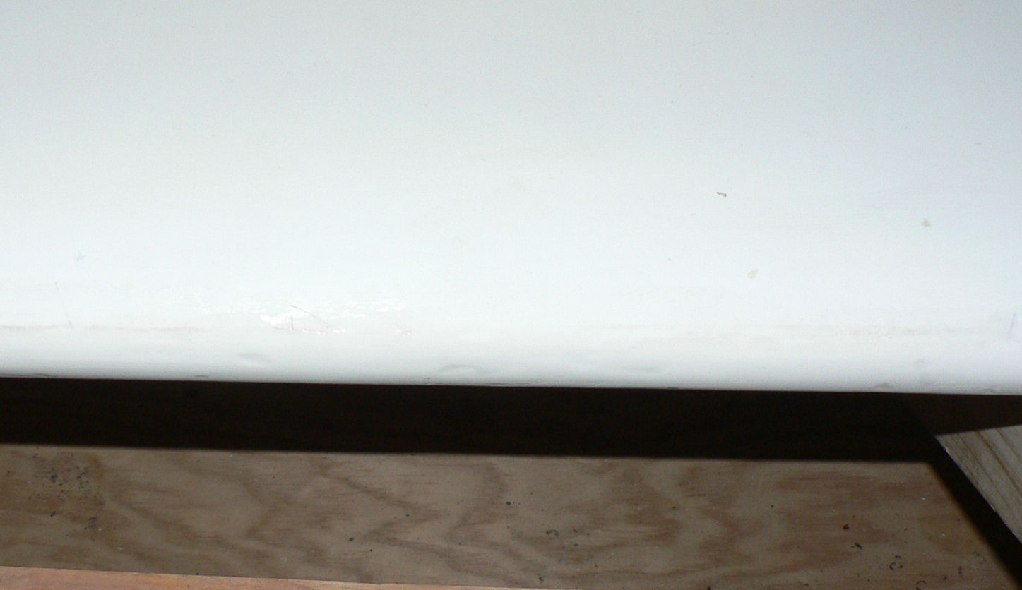
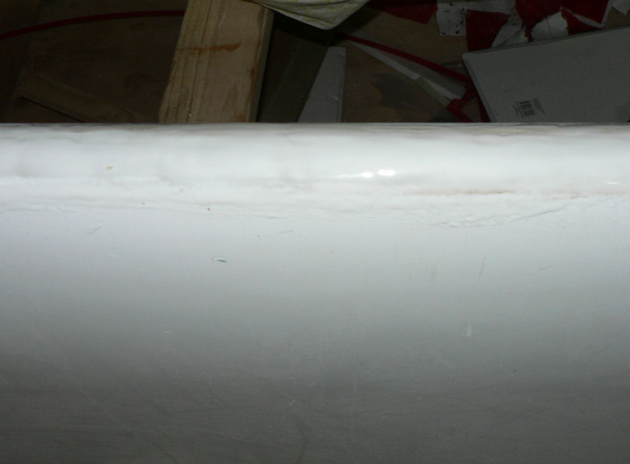
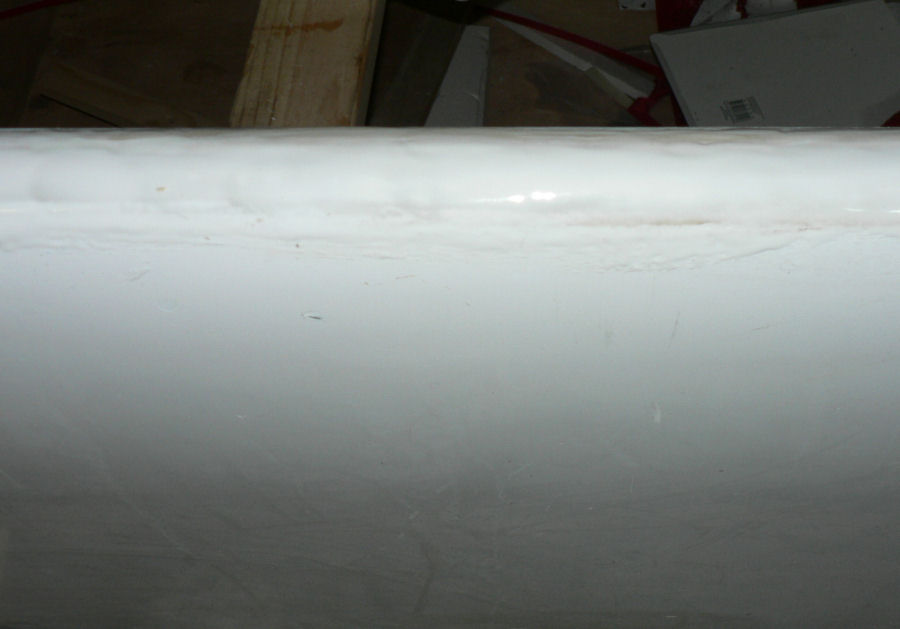
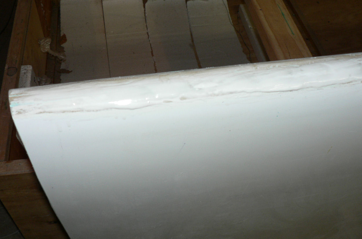
07-07-07 Scraped the leading edge of the LH wing to match the top of the leading edge template and also scraped the wing tip. Orbital sand the LE of LH wing. Hand sand the LE of LH wing. Cleaned up some spilt epoxy in flap channel recess on RH wing residue from flap hinge attachment points. Drilled some countersinks in pre-drilled holes in aileron attachment plate RH wing for later filling with epoxy micro-ball mix. It looks reasonable from the top side of the wing. [ATTACH]2552[/ATTACH][ATTACH]2553[/ATTACH] But the bottom of the profile has a gap of about 2.5 mm over most of the length of the LH wing at the end of the template.:confused: 9-07-2007 I rang Rod Stiff, managing director at Jabiru, this morning a few minutes ago re the profile of the wing. He said that as long as the shape of the curve at the join in the leading edge was as per the template the rest of it basically was less important because they were all made in the same moulds and that whatever that shape was that it was the same for both wings and along the wing. It is also a very forgiving wing design and most dimensions are not critical. I read that as saying that my wings are fine once I smooth up the rough bits - a fairly minor job! I shall have to check the RH wing with the new template as well. So the LH wing section is thinner than the template by about 2.5 mm at 103 mm from the leading edge. [ATTACH]2549[/ATTACH]West[ATTACH]2550[/ATTACH]North[ATTACH]2551[/ATTACH]East This morning 7-07-2007 weather in Leeton about 8 mm rain overnight another 3.5 during the day.
-
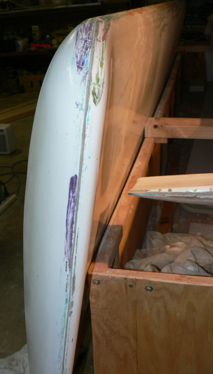
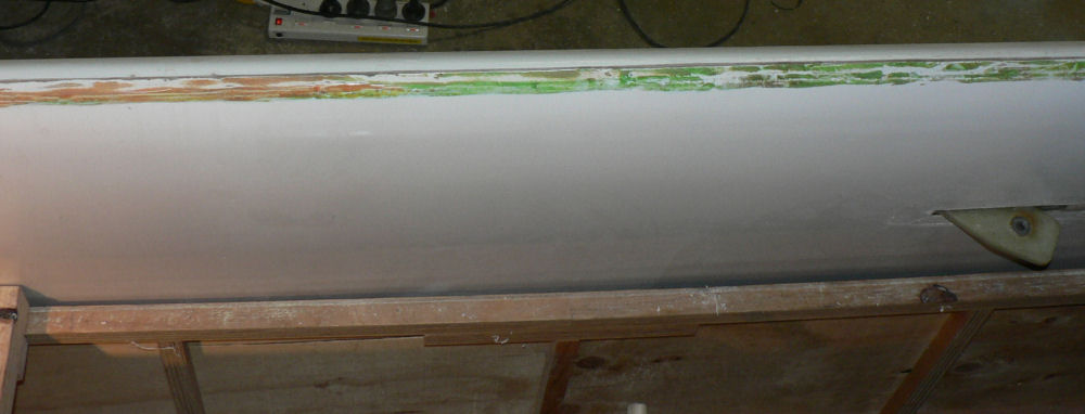
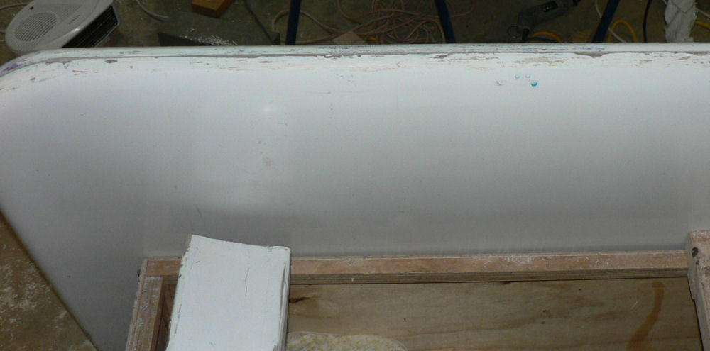
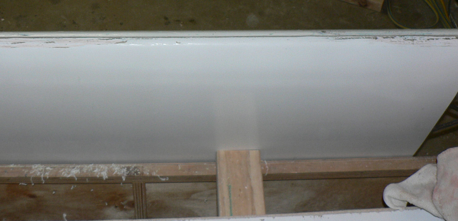
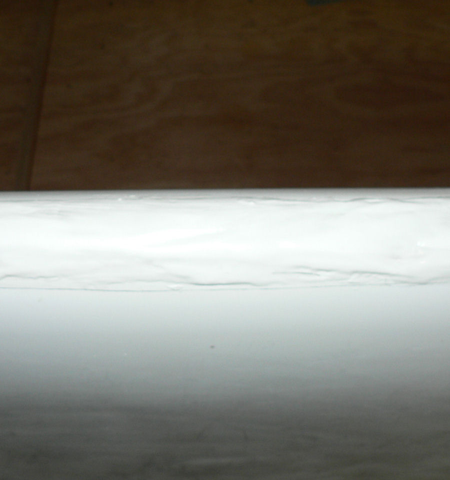
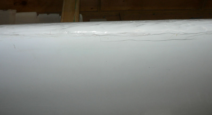
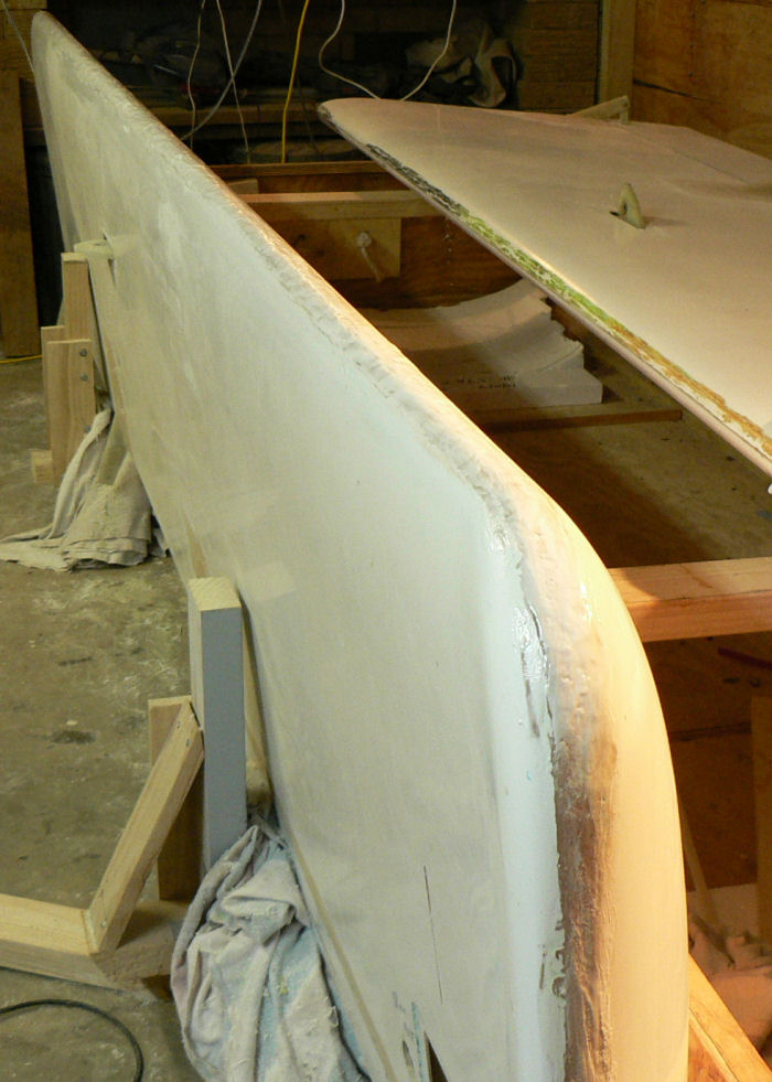
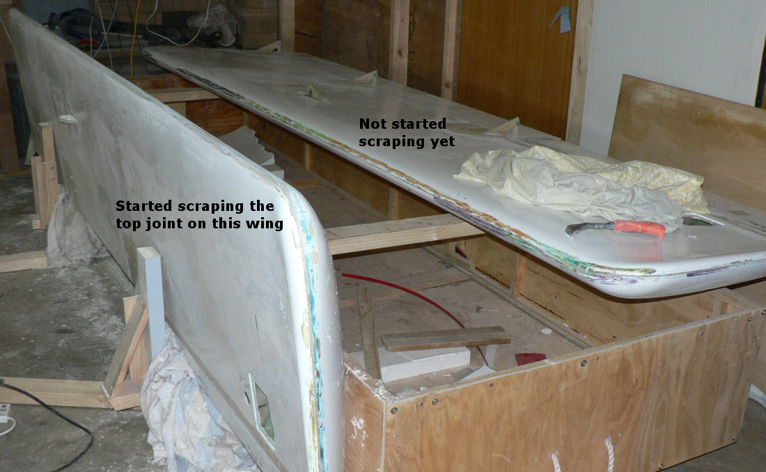
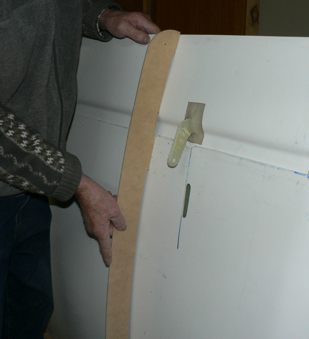
6-07-2007 Stood up LH wing and checking out the leading edge with the almost refined template. The wing is generally thinner than the template by some two to three mm. I can probably dress a bit more of the epoxy bead off the leading edge join which will help but the section varies from one end to the other making adjusting it more difficult. So far have scraped off the wax and polyester filler and then rubbed it down with acetone to remove any residual filler or wax and grease. Will repeat that exercise tomorrow. [ATTACH]2537[/ATTACH][ATTACH]2538[/ATTACH][ATTACH]2539[/ATTACH][ATTACH]2540[/ATTACH] Condition of wing tip much better than RH wing tip. [ATTACH]2541[/ATTACH][ATTACH]2542[/ATTACH][ATTACH]2543[/ATTACH] After initial scrape of edge and rubbing with acetone
-
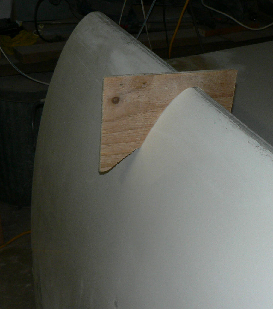
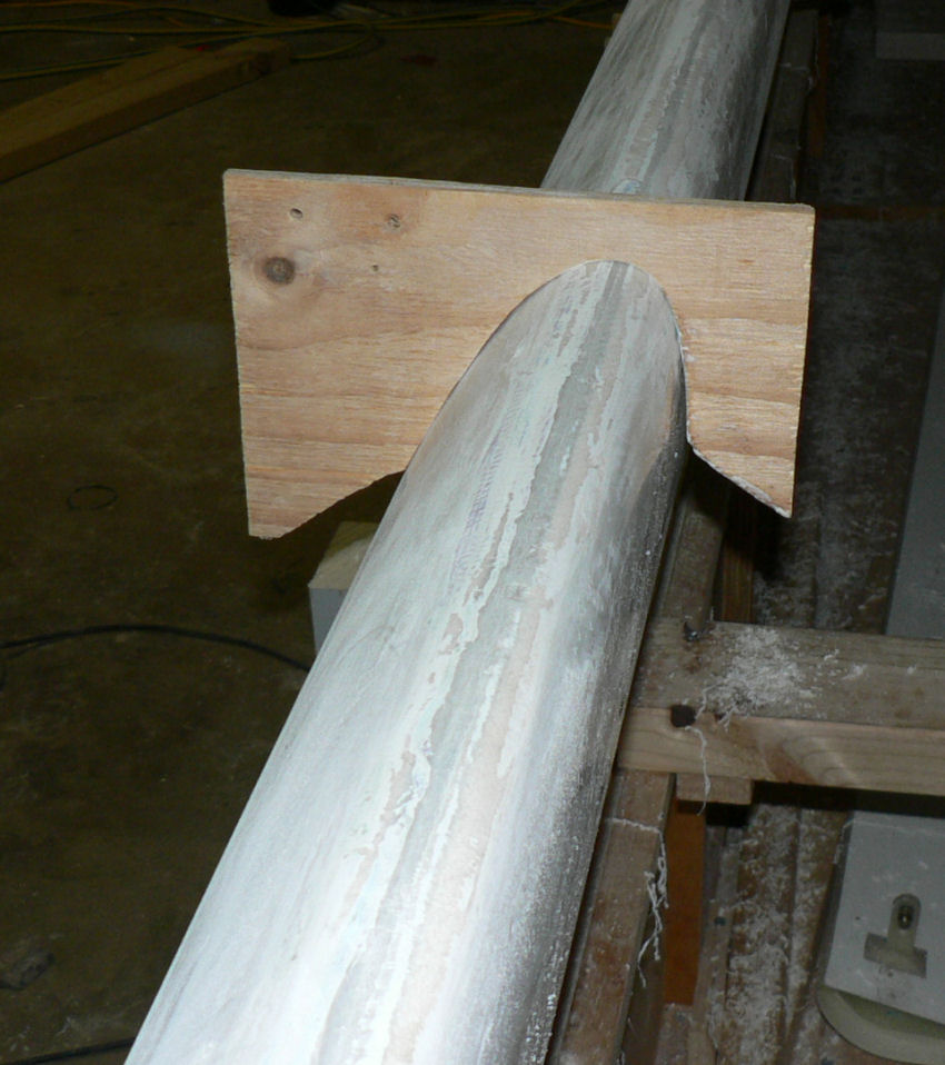
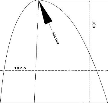
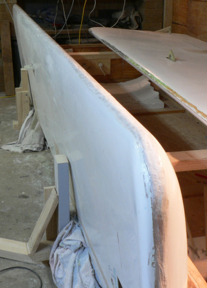
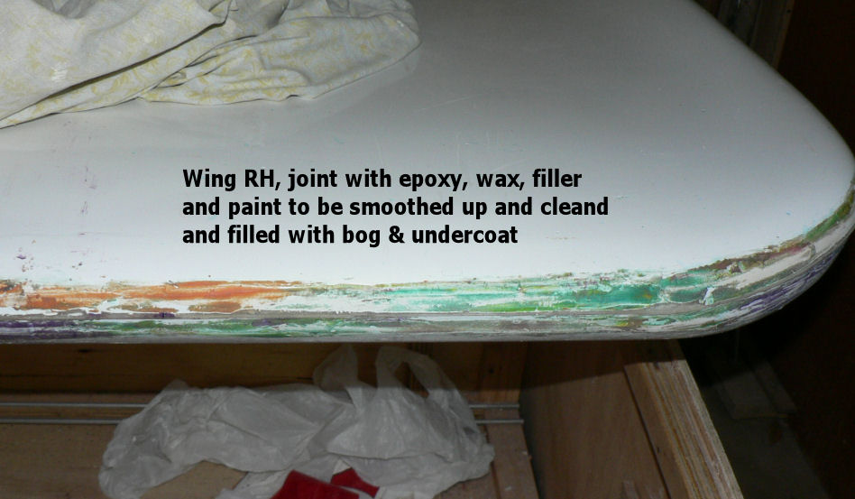
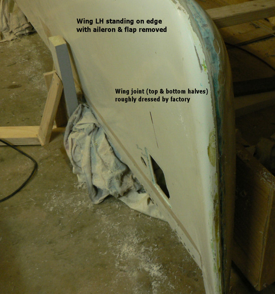
Hi Geoff & Brentc If I had access to somebody that knew what they were doing I probably would have done the same as you Brentc. It's a steep learning curve for first timers. I was aware of the care that glider pilots took of "profiling" their wings from my previous life although I had no experience of it so I needed that drawing! I was not very impressed with mine either as there seemed to be a bit of abrasion due to movement while being freighted I presume but not nearly as bad as yours was Geoff. It must have been pretty disappointing. On mine the foam packing dividers protecting the wings had moved substantially. Mine came from Brisbane as road freight on a semi-trailer with a Leeton carrier having been already sent to a Brisbane depot by Jabiru. My wings apparently had a bead of epoxy projecting from the leading edge which had been dressed off with an angle grinder by the factory. But the join is actually stepped instead of being lined up and according to the drawing this is right near the middle of the leading edge (or some kind of tangent to it) at the point where the air going over and under the wing splits! I have just set up the LH wing to discover that it is pretty good I think and in better condition than the RH wing was. There seems to hardly any chipped gel coat aside from the ground off epoxy joining bead area. There is a negligible step at the leading edge join making profiling the leading edge much easier. I will see much better once I clean up the wax. Therefore I needed to know what the shape of the leading edge was supposed to be. So I am filling it with epoxy micro-balls and trying to dress it back to the "right shape". [ATTACH]2534[/ATTACH] The 107.5 mm dimension refers to the width of the bottom of the section - not where it is on the drawing. This is the JPG drawing that I ended up deriving from the Jabiru PDF file for the leading edge. Because of the cropping that was necessary I did not have to reduce the file size to upload it to the forum.
-
5-07-2007 This afternoon Jabiru sent a PDF file drawing of the first 103 mm of the leading edge of the wing. After some hours of experimentation I opened the PDF file with the "Paint Shop Pro X" picture program and saved it as a JPG file. Cropped the file drawing back to the dimensions of a rectangle that the drawing's maximum dimensions would fit which was nominally 107.5 mm thick by 103 mm back to the leading edge. Then dimensioned the drawing with the dimensions inside that box instead of outside as was the original. Set up a "print layout" with a horizontal grid spacing of 53.75 mm. Dragged the drawing onto that grid and stretched it until the thickness section of 107.5 mm fitted across two of those grids 2 x 53.75 = 107.5 mm. Saved the template and printed it on glossy paper. The result so far agrees with the supplied dimensions within about 1.5 mm. Now I am going to bed after I compare the drawing with the template that I have already made! It is very close and will only require about a 2 mm fill on the template I have made for about 50 mm length on part of the underside profile. Later on 5-07-2007 Scraped the micro-ball filler and then used the orbital sander on it then the hand sander which is longer to provide a smoother finish. A couple of photos here taken on 6th July but named as 5th July. [ATTACH]2535[/ATTACH][ATTACH]2536[/ATTACH]
-
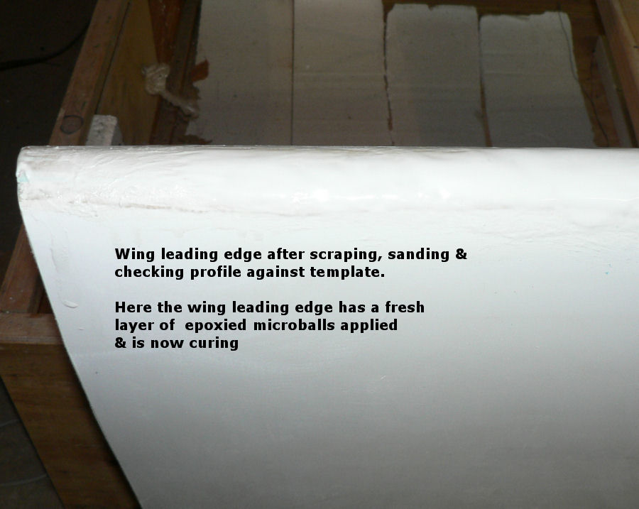
4-07-2007 The RH wing leading edge was scraped then sanded and the profile checked against the newly made template that I dreamed up & cut out. See photo below. There were quite a number of low spots so another batch of epoxy microball filler was made up fairly liquid and applied with a paint brush (better than the stiffer gglue brush) over the leading edge length of the wing. It it is now curing before dressing up with scraper & sander and checking against the template. The other wing will be easier and quicker with this experience & template. [ATTACH]2519[/ATTACH][ATTACH]2520[/ATTACH][ATTACH]2521[/ATTACH][ATTACH]2522[/ATTACH][ATTACH]2523[/ATTACH]
-
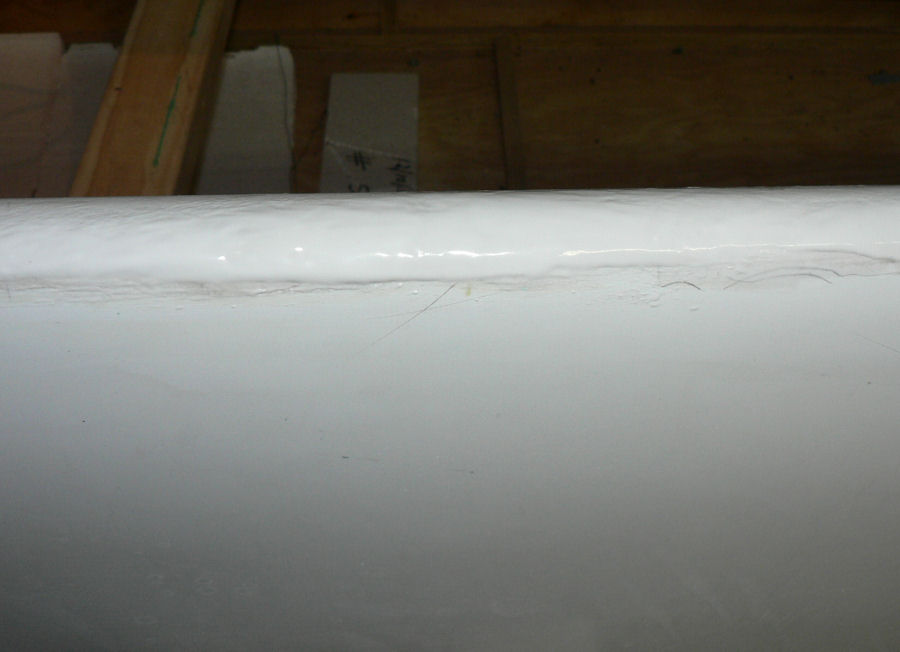
3-07-2007 No word from Jamie yet re the profile. Made up a batch of epoxy supplied by Jabiru. As usual mix 1 part by weight of epoxy hardener with 3 parts by weight of epoxy resin. Mix it until the colour changes slightly. Temp in the garage with heaters going is over 20 degrees Centigrade. Applied a thin coat of the epoxy to the leading edge to prime it. Mix in micro-balls with the remainder of the mixed epoxy until it is still pliable and sticky. I actually used a fairly stiff narrow glue brush about 2 cm wide to apply the microball mix along the leading edge. It may need more after scraping and sanding or complete the filling using the bog paint with the spray gun. The micro-ball epoxy sets harder than other fillers and does not continue to shrink after the initial cure. It is far lighter than using a flock epoxy mix and is far easier to scrape, sand and work. The micro balls are so light that if you put your fingers in a bag of the micro-balls before they are mixed with the epoxy it is difficult to feel them. So be very careful while mixing as they float in the air like an extremely fine dust. I put extra photos in because the camera seemed to have trouble auto focussing on the wing section. [ATTACH]2511[/ATTACH][ATTACH]2512[/ATTACH][ATTACH]2513[/ATTACH][ATTACH]2514[/ATTACH][ATTACH]2515[/ATTACH][ATTACH]2516[/ATTACH]
-
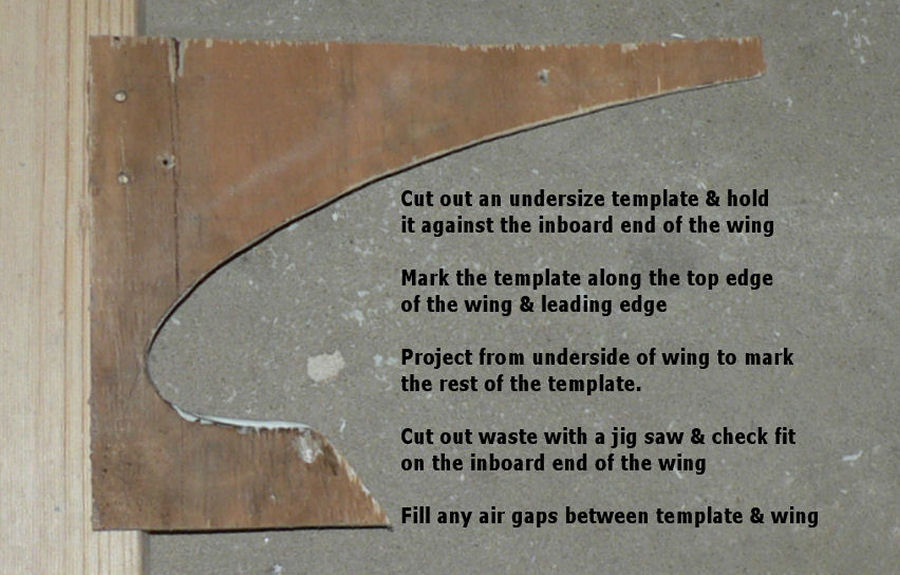
2-07-2007 Finally rang Jamie at Jabiru at 12:15 today who said they did not have an available wing leading edge template but could send an Autocad file of the wing profile. I did not have a current Autocad program to handle it so he is trying another strategy. Meanwhile I have discovered from Jamie that the wing profile & therefore the leading edge, as well, is uniform for the whole length of the wing. So I have started to make a plywood template to fit the leading edge wing profile very close to the inboard end of the wing. This is the most uniform part of my RH wing and actually looks like a wing leading edge. It also looks very like the not to scale sketch in the construction manual for the installation of the stall warning sensor. Making the leading edge template is obviously the first thing I should have done. A local LAME's response to finding out that I was putting a kit together was to "make sure that whatever you do on one side of the aircraft you do on the other". Luckily we don't have to cope with passengers doing laps up and down the aisles.
-
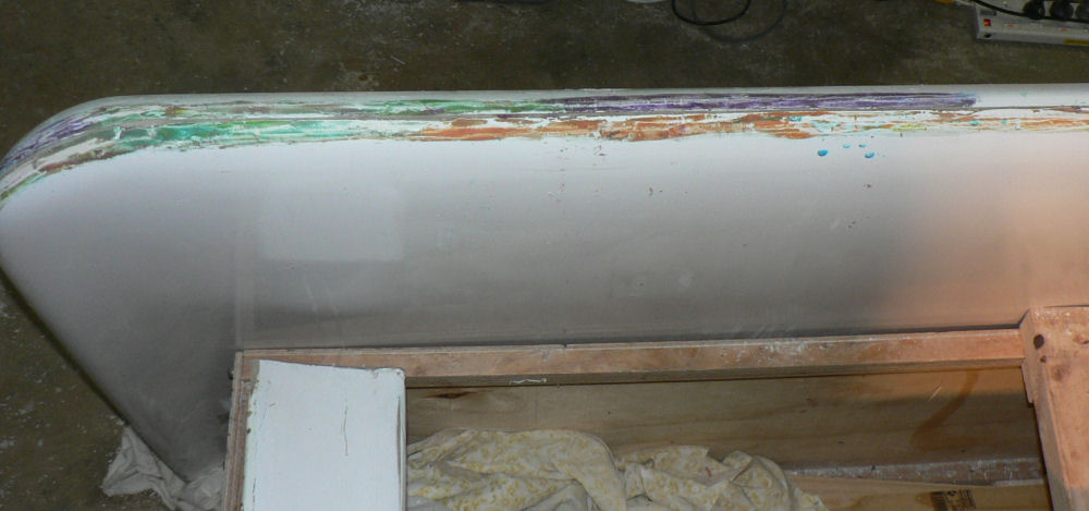
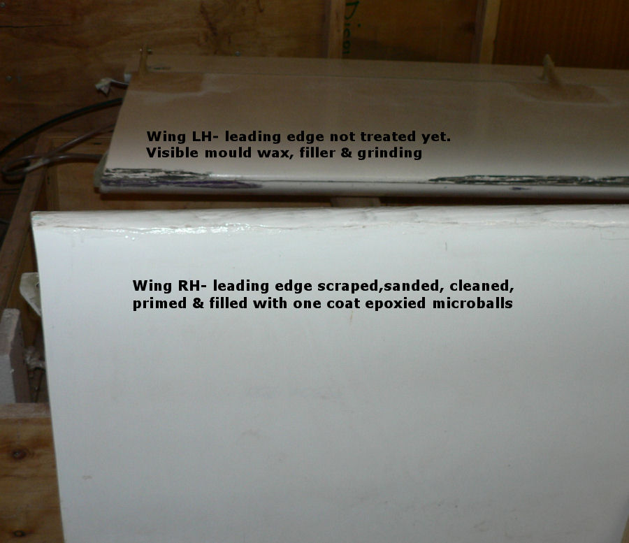
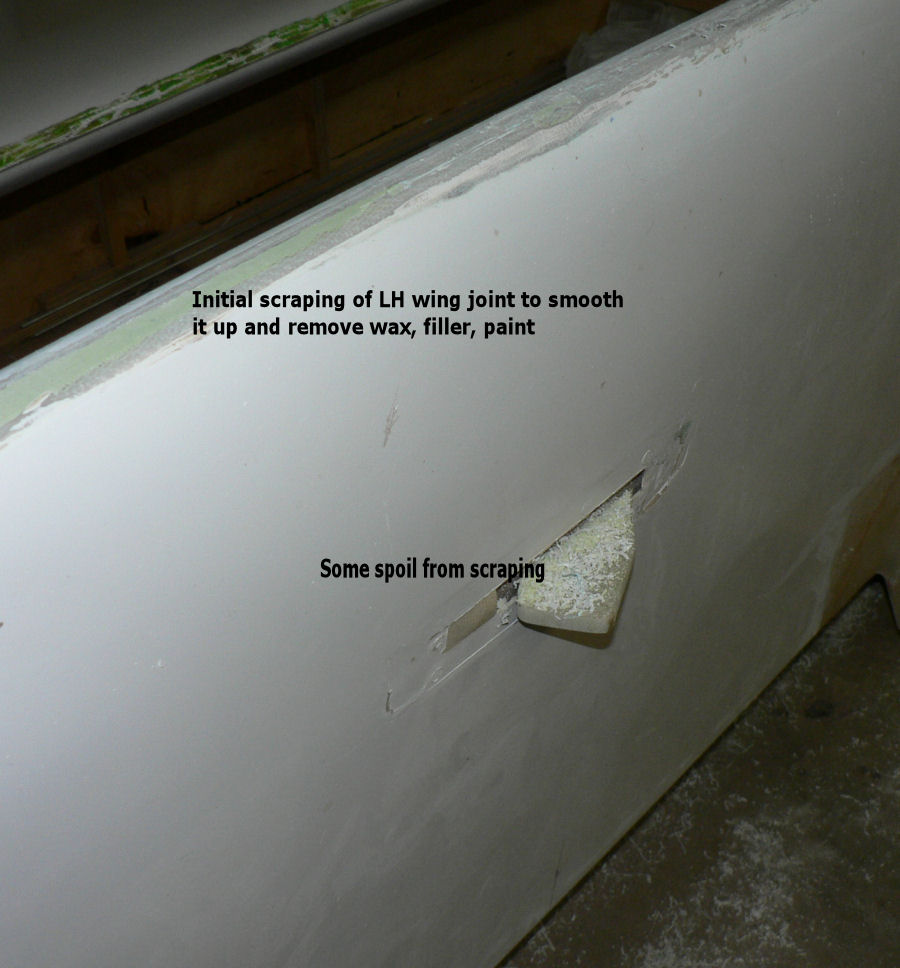
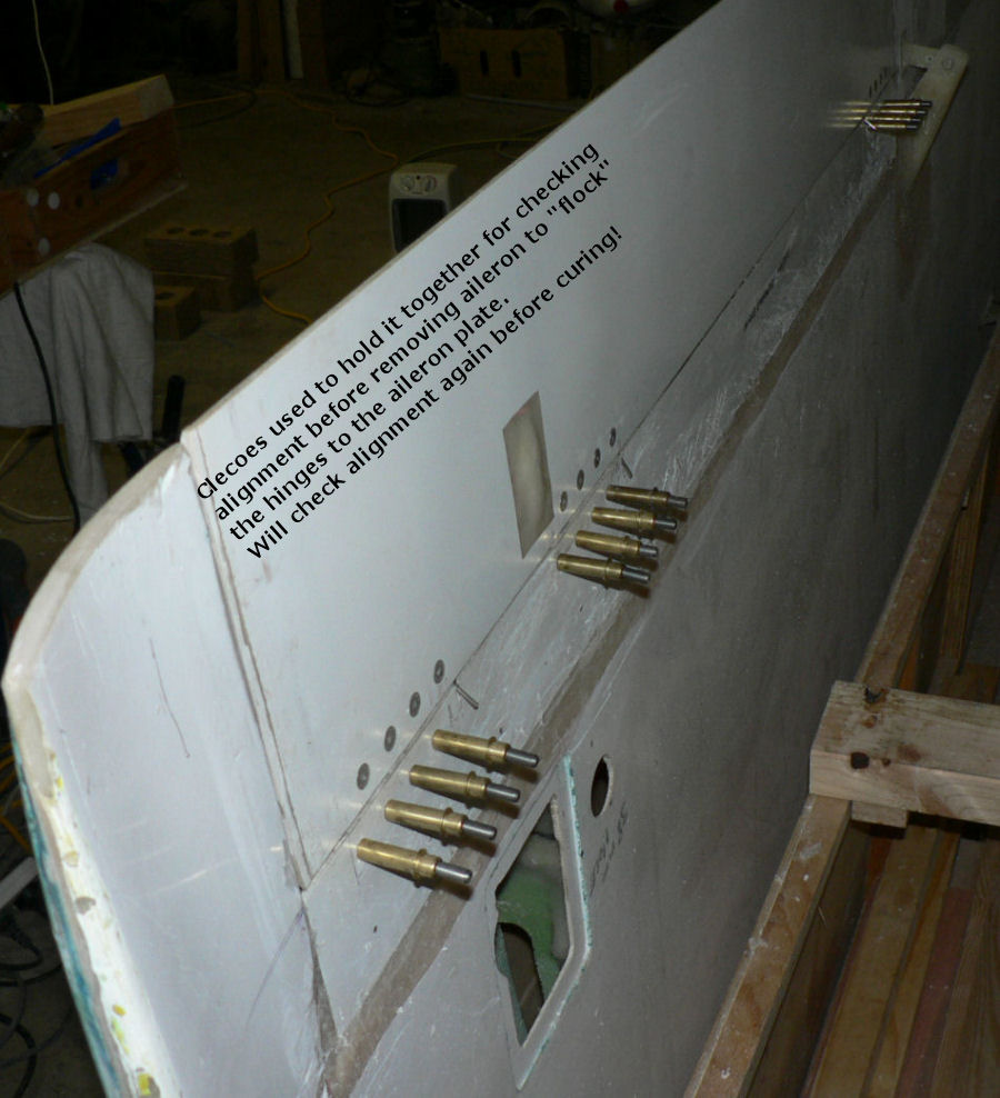
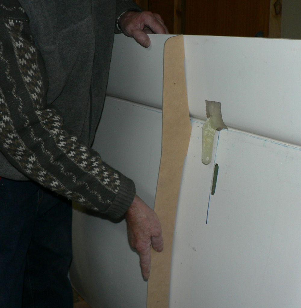
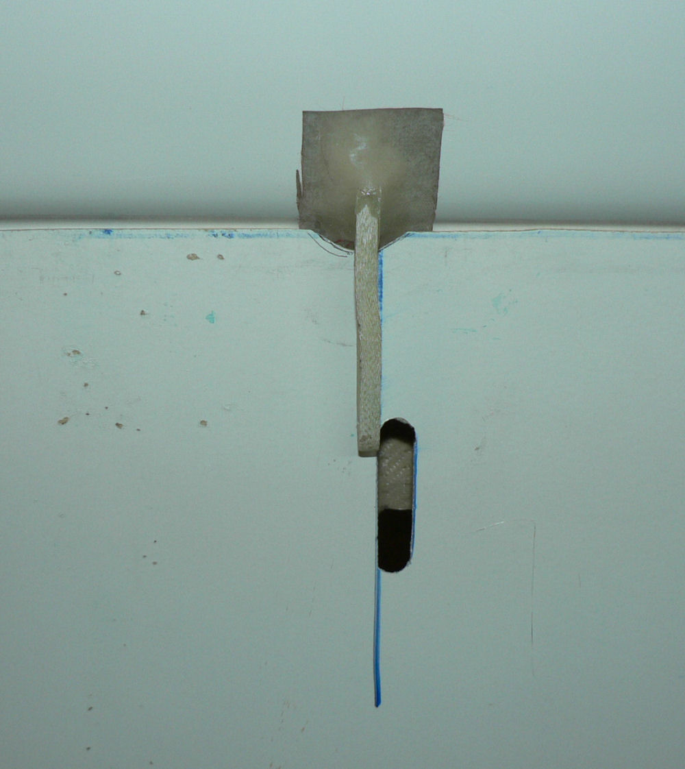
29-07-2007 Because of the AC position in the garage it is not convenient to try the LH wing on the AC at this stage. I thought about doing the Stall warning fitting in the leading edge of the LH wing at 1.215 m outboard from the wing root but the leading edge joint is fairly irregular so it needs tidying up before first. So removed the flap and aileron from the LH wing and stood the wing on its trailing edge with some padding to protect that edge. Used a scraper to clean up the top edge of the LH wing as the material to be removed varies from cured composite fibreglass, epoxy, wax, paint and some kind of filler. Will also do the wing tip edge which is pretty rough. After dressing up with the scraper it will be washed/rubbed down with wax remover and acetone followed by sanding and filling. Rang Jabiru to see if I could get a template for the wing leading edge. They will let me know on Monday July 2. [ATTACH]2444[/ATTACH][ATTACH]2445[/ATTACH][ATTACH]2446[/ATTACH][ATTACH]2447[/ATTACH][ATTACH]2448[/ATTACH]
-
Hi Disperse If I had invested the money that I put out for my kit almost three years ago I could now have bought a factory built version of the same aircraft for cash and have plenty left over. ;) (but I would not have the experience of building and my wife would probably have a three year old car instead of a nine year old one. That car is now far cheaper to own than a new one). If I had borrowed the money that I put out for my kit plus extras (I stopped counting around $60,000) I would probably be paying it off for five years or more as I would be spending a lot of my cash flow on flying expenses! I would get in more flying a definite plus! As it is I am spending it on occasional hiring of commercial mainly training aircraft and am still up for mods that have come out after I bought my kit. With a bit of luck and perseverance I should get to the ;);) stage by Christmas (2007 I hope). I think a syndicate might be a great way to go whether building from a kit or buying a factory built. But the syndicate needs good rules and protection against inexperienced flyers and must be insured. There may be varying amounts of flying that are done by the members and there needs to be a fair way of allocating costs in that situation between fixed overheads and variable costs. Enough waffle - Best of luck for your decision. Regards
-
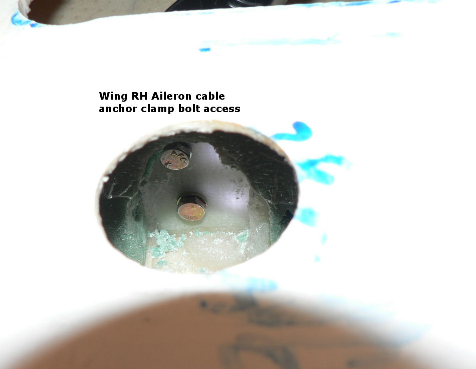
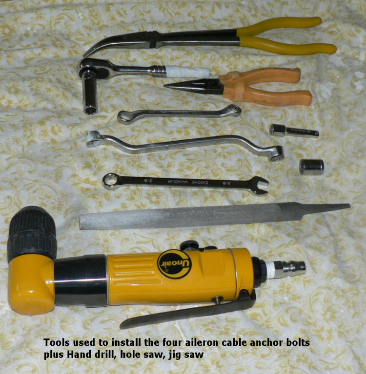
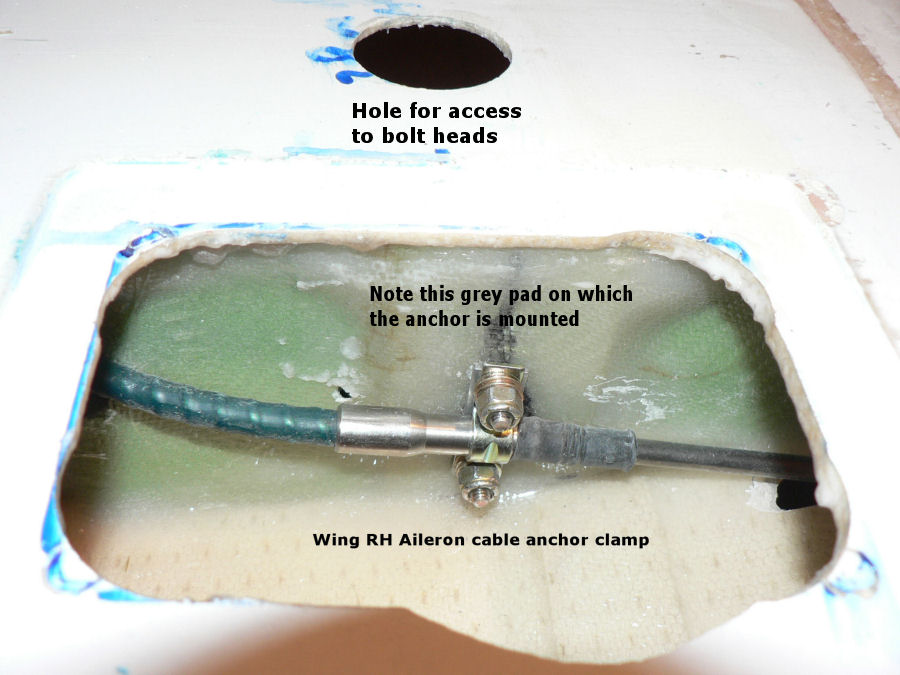
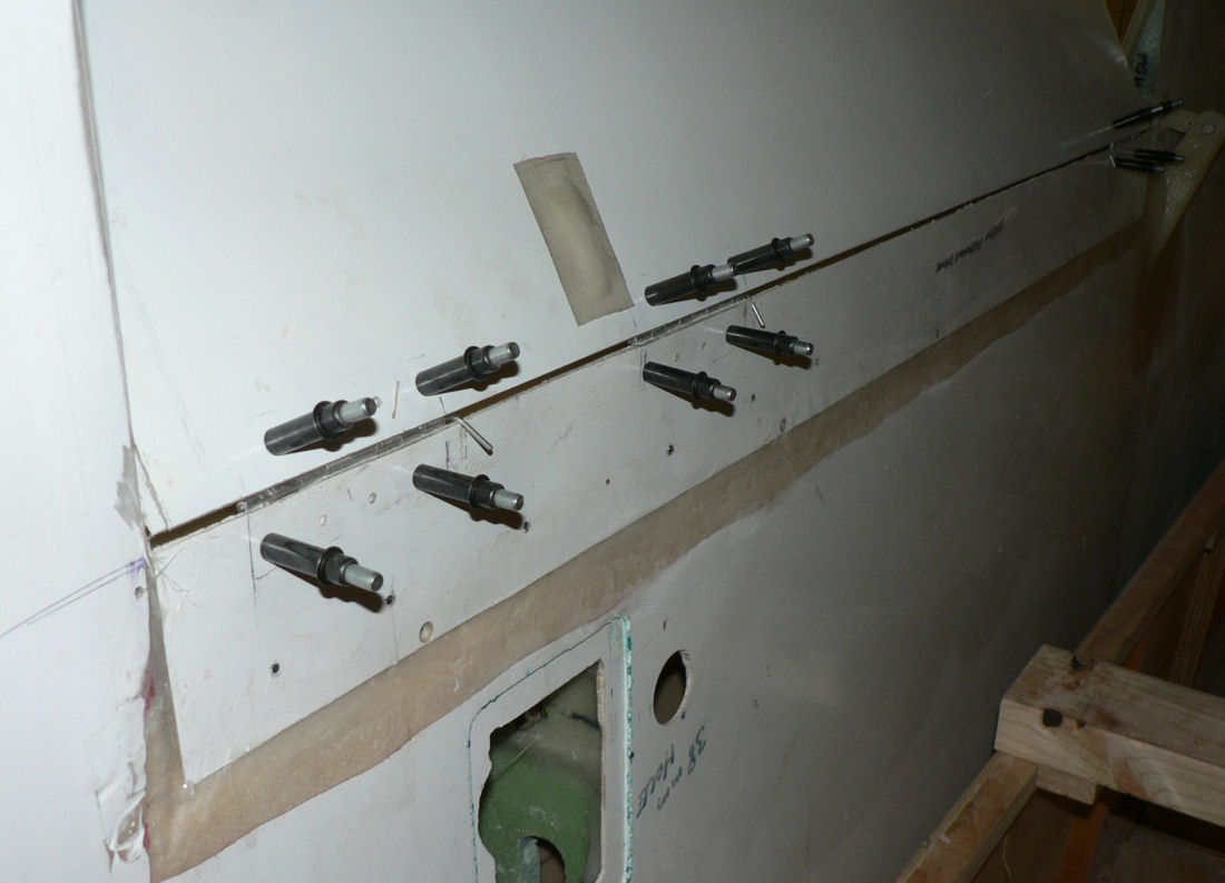
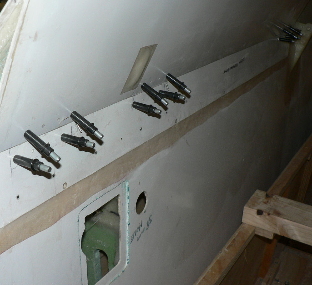
27 and 28 -06-2007 Needed the right angle drill to finish off the aileron anchor plate bolt holes that were already half drilled by the factory. I had done this earlier some days ago. Installed appropriate length AN3 bolts in both LH & RH aileron cable anchors so needed long bent nosed pliers to facilitate that job. The bolt length varies depending on the thickness of the fibreglass where each end of the cable anchor is installed to achieve at least three exposed threads above the tightened nut. I put two washers under the nuts and one under the head so that I could get a grip on the nuts with a thin walled ring spanner or socket spanner and the long ratchet socket on the bolt head end because it is the only kind of spanner I can get on the bolt head aside from using the long nosed pliers. Because the bolt heads are in a recess, I needed a tube ratchet spanner to get the right length for access through the wing skin hole that had been cut with the hole saw. [ATTACH]2436[/ATTACH] [ATTACH]2433[/ATTACH][ATTACH]2434[/ATTACH][ATTACH]2435[/ATTACH] Needed the long bent nosed pliers to insert the bolts and cannot see the top bolt hole unless some material is shaved off or filed off near it. Installed the six aileron hinge pin retainers in place for the LH & RH wings ensuring that retained nut were free of epoxy.
-
Hi Yenn It was a J230C and I cannot tell you whether it was short or long wing. My guess based on the round out and its stable flight was that it's a standard short wing and very smooth to fly. It takes a while to stop sinking in the round out, full flaps - my first landing was firm with no float rather than a greaser. I looked up the Jabiru web site and did not see any wing options for the Jabiru J230C although reading about the J170 further on the site it says that the J170 ... uses the longer wing of the J230 which would probably have needed a new wing configuration to keep the landing speed within allowable limits. On checking the site further I see that the J230C and the J230 wing length specifications are different from the those quoted for the J170C and the J170. And there are differences between the quoted wing lengths as opposed to the lengths including the winglets between the 170 and the 230 models. According to the site the J170 wings are slightly longer than the J230 & J230C wings. I have not taken the trouble to compare the wing areas etc which is probably pertinent to the argument. Regards
-
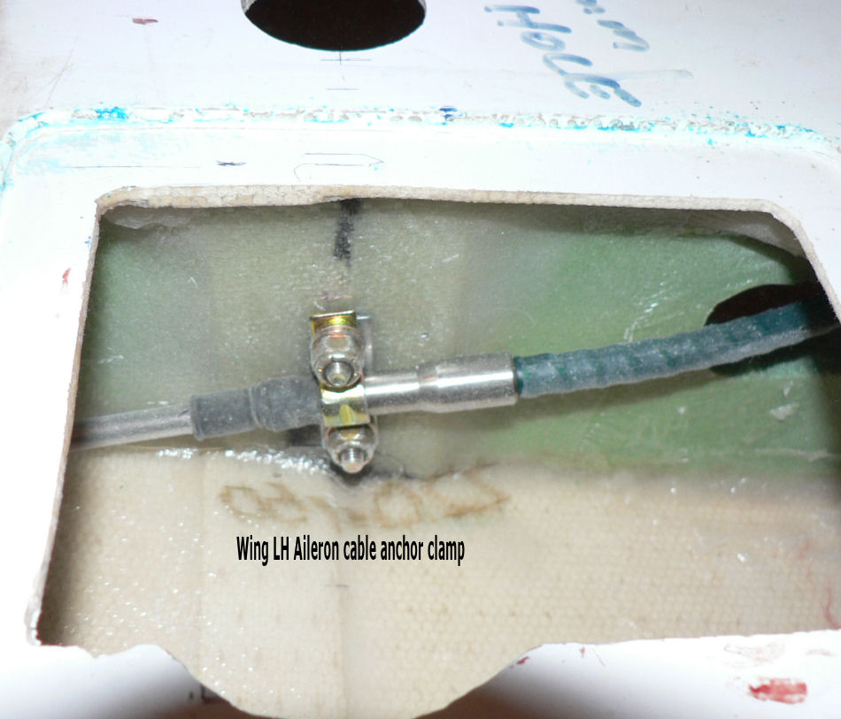
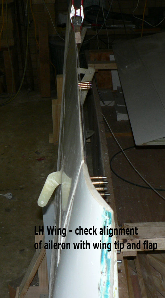
26-06-2007 Not a lot done today a few other jobs to do. Checked aileron hinge alignment after flocking & riveting yesterday - pins easy to slide in OK. Pulled the aileron cable for the LH wing and not yet anchored as I will need a longer set of long nosed pliers to manipulate a shorter set of bolts into the cable anchor point at the LH wing tip. Will need to file the cable slot a bit to remove interference with the cable end. Reinstalled the RH aileron on the RH wing and connected the aileron cable to the aileron - cable previously anchored at the wing tip. I have installed four rubber tyred caster wheels to support the wing box and make it easy for one person to move it around the garage or outside - an easily moveable work bench. Wheeled the wing box over near the fuselage and stood the wing on it's edge with the trailing edge uppermost. Connected the RH wing cable through the rear window opening to the aileron anchor point on the back of the RH seat and added the cable end to the cable and connected it to the control behind the seat. Operated the control stick full left and right and the aileron moved accordingly and appears to have enough adjustment to get it in the right working range as indicated in a note on the Jab site. Disconnected the aileron cable from the control stick and the anchor point behind the passenger seat. Lay the wing down flat on top of the wing box. Wheeled the wing box back away from the fuselage.
-
Hi hfrensch My J160 is yet to fly. I changed my bolts in my J160 #14 kit from 5/16" to 3/8" which was flagged as an optional mod and "only done by Jabiru on the J160 by the factory to try to increase the common spares over their model range". Paul Middleton even wrote a piece on it in the magazine before the recommendation came out explaining that at that time the UC and the seat belts shared the same bolts which would not do you much good if the bolts did not fail in a crash. So as Paul pointed out the seat belts were on the same bolt as the UC so it was designed to fail in a crash. So if you put in 3/8" bolts for the UC which could tear a hole in the cabin floor in a crash the seat belt anchor need to be moved away from the UC bolts otherwise your lower half could be dragged through the botton of the cabin near the seat together with the UC in the case of a crash that removed the landing gear. Hence the modified arrangement of the seat belt anchors that was eventually put out by Jabiru to go with the larger UC bolts. My kit for the J160 came with or I was eventually sent the extra pieces necessary to mount the seat belt anchor bolts on separate bolts away from the UC mounting bolts. It caused me some confusion at the time because of the many changes done in the early J160 kits. So I had mods to do while building the kit. I think it would be sensible to do regular checks of the UC system to make sure that there is not excessive play in the system otherwise shock loads will be magnified increasing stress on the components the fibreglass and the bolts. This would involve removing the cover plate below the UC to get access to the bolts but might also involve adding extra washers under the nuts inside the cabin behind and under the back of the seats. This area is fairly difficult to access once you have installed the windows in a J160. I don't know about other models. The same kind of remarks apply to a number of the oil pump modifications for the early 4 cylinder motors including mine but mandatory for early 6 cylinder motors I think because the failing of older style oil coolers. I think it would be prudent to do the oil pump changes as well but the original oil cooler was made of aluminium which in my opinion would probably not like multi-millions of rapid reversing loads from the oil pump no matter how small. I don't know what the later model oil cooler that I was supplied with in the kit is made of but it is a different colour. I know of at least one early J400 series that without warning except for not being able to see through the windscreen lost its oil on the way to Natfly a few years ago about the time the first J160 kits were being ordered. Much of the oil ended up across the wind shield. They did a dead stick landing in a paddock, disconnected the oil cooler, filled up with diesel engine oil from a local farm and flew it a very few miles to an airfield with a rapidly rising oil temp and waited there for another oil cooler. They arrived a day late. I think on his way home his manifold bolts came loose or maybe that was another trip but the same plane. Regards
-
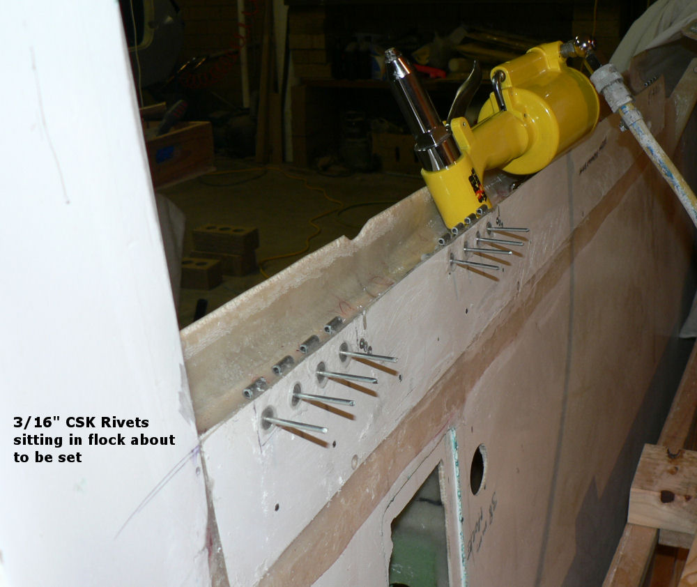
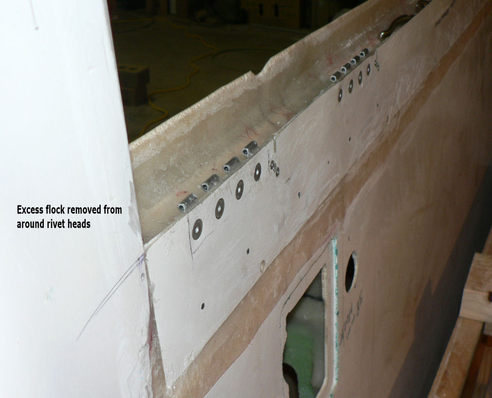
25-06-2007 Set the house airconditioner to take the chill off the garage this morning by leaving the connecting doors open. OAT was 1 C here this morning on the East side of the house. The 12 attached photos explain the days two lots of epoxying or flocking sessions with the last session about cured enough to turn it off now. [ATTACH]2391[/ATTACH][ATTACH]2392[/ATTACH] [ATTACH]2393[/ATTACH] [ATTACH]2394[/ATTACH] [ATTACH]2395[/ATTACH] [ATTACH]2396[/ATTACH] [ATTACH]2397[/ATTACH] [ATTACH]2398[/ATTACH] [ATTACH]2399[/ATTACH] End of first epoxy & curing session Start new epoxy session to bed in 3/16" rivets in aileron plate hinges. [ATTACH]2400[/ATTACH] [ATTACH]2401[/ATTACH] [ATTACH]2402[/ATTACH] System would not let me insert the last curing picture - slightly different from the previous one but a different photograph- note the different fan heater set on low setting in picture 4. Found that for tight hinges (slightly misaligned) applying heat with hot air gun on low relieves stress but was not needed on todays sessions. 23:30 Curing finished - checked hinge alignment again OK. Building Log Book 1 full - start new log book.
-
Thanks Roger Wally is very good for the ego when flying with him and really knows how to get the most out of a person when flying an unfamiliar aircraft. The J230 seemed such an easy aircraft to fly today anyway when we had about a 45 degree cross wind probably about 8 knots or so. When doing steep turns (I only did two or three each way) it was fairly easy to hold it in a steady steep turn although I did gain 500 feet while trying to figure out where one of the radio calls was coming from and watching the Sportstar below us as his shadow got very close to the aeroplane. He was simulating picking a paddock for a forced landing! One of the problems (my problem) was the faster speed in the circuit than what I am used to and getting the checks done at the right time and flying the aircraft - but I think I was getting reasonable (for a first time) by the end of the exercise. At least in this particular aircraft J230 you have a set of flight instruments all together right in front of you (when I learn to read all the items on the glass panel). The big wide circuits I was doing gave me a bit of leeway in catching up and eventually getting in front of the aeroplane. Regards
-
Hi Geoff I forgot to take much notice of the "landing light" except that it has a clamp type mount around the strut similar to the alternative strut tie down points but I really did not take any notice. I only had time to take those photos. I shall have to get more detailed photos next time if I remember. I suppose it still has a hole in the strut for the wiring. It was rapidly getting dark as I took those photos. I couldn't actually see any detail while doing the panel shots - just a black blob until the flash went off. (I've had the cataract removed and a lens implant that is fantastic) Regards
-
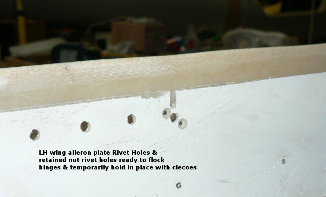
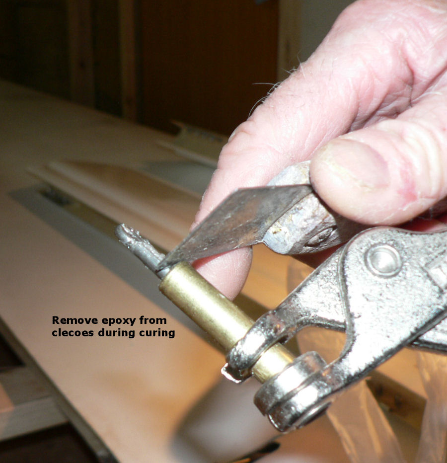
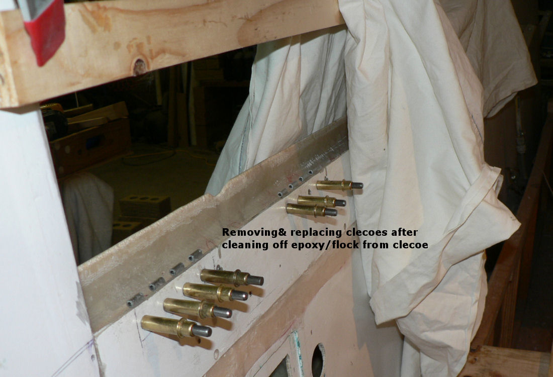
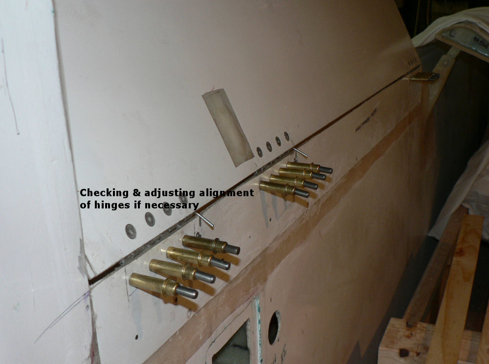
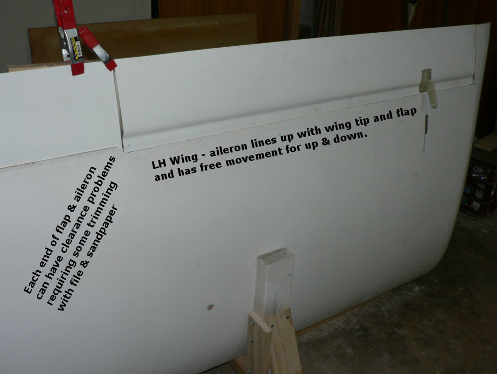
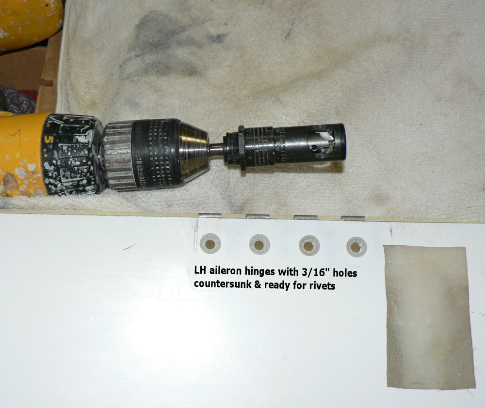
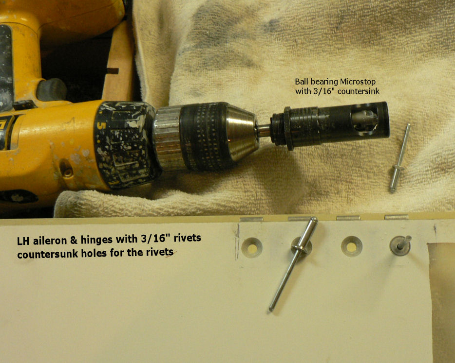
24-06-2007 Drilled the holes in the LH wing aileron plate to 3/16" after adjusting alignment with 5/32" clecoes. Inserted 3/16" clecoes. Checked alignment along aileron with flap & wing tip. Checked full & free movement of ailerons prone to have interference on ends which needs filing and sandpapering. [ATTACH]2382[/ATTACH] [ATTACH]2383[/ATTACH] [ATTACH]2384[/ATTACH] [ATTACH]2385[/ATTACH] After that I drove to Narrandera and had my first dose of J230C courtesy of Wally Rudin. The after effects, and I can still feel them, are a broad smile after an initial reaction of where is .... and where is ..? Made my day! Next step (will be another day), remove aileron sand hinge & hinge attachment point, clean hinge and hinge attachment points with acetone. Prime hinges & hinge positions with epoxy Apply flock & assemble using 3/16" clecoes Check and adjust alignment Cure and remove clecoes after curing, check alignment again etc. I remove & replace clecoes periodically during curing to remove epoxy/flock from the clecoe otherwise I may have to fly the aeroplane with clecoes fitted. Regards
-
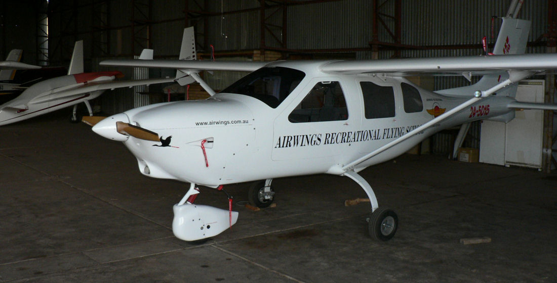
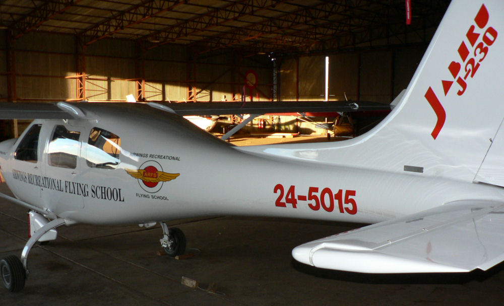
Hi Crew Today I had to stay home for a while to top up our water tanks from a small special watering so I did a little work on the J160 then it got to me. Due to a violent attack of withdrawal pains I drove over to Narrandera AD 30 km to be confronted by Wally Rudin who had no one to fly with. Not only but also he had his brand new Jabiru J230C out of the hanger and ready to fly. So we had 0.9 hour dual touch & goes and a few steep turns to give Ted Celi's twin Jet room to land and then back to the gravel strip 05 for a full stop landing across the main strip 32 and back track up to 32 and back track to the hanger. That was my first flight in a J230 (2 seater, 6 cylinder 3300 ccs). A very nice aeroplane so far in my limited experience. What I have noticed so far is greater performance in climb, more momentum in landing, need to round out a tad earlier than lighter Jabs. Wally's plane has a transponder, a Garmin 296, Glass flying instruments, plus steam gauges w/o VSI, fuel level display on panel plus sight gauges and a Y shaped stick with a press to talk button on each arm of the stick. It has electric flaps with an indicator on the RH forward door pillar. It has two good radios of which only one (at a time??) can transmit. Some photos of Wally's new J230C with the sun setting over the YNAR terminal as I finished. Wally's Tecnam's tail is in the LH side of the first photo. [ATTACH]2377[/ATTACH] [ATTACH]2378[/ATTACH] [ATTACH]2379[/ATTACH] [ATTACH]2380[/ATTACH] [ATTACH]2381[/ATTACH] As I started to drive out the private syndicate Narrandera J230C landed and taxied in to the hanger. Roger & Ian Duff had had a nice afternoon flying to Wangaratta then Yarrawonga then Narrandera. Steve Beck (ahlocks) from Wagga (Wagga) together with his instructor Greg Wardman was also doing his thing in a brand new low wing Sportstar of which I did not get a photo while Wally and I were enjoying ourselves in the J230C.
-
What Pilot? Regards
-
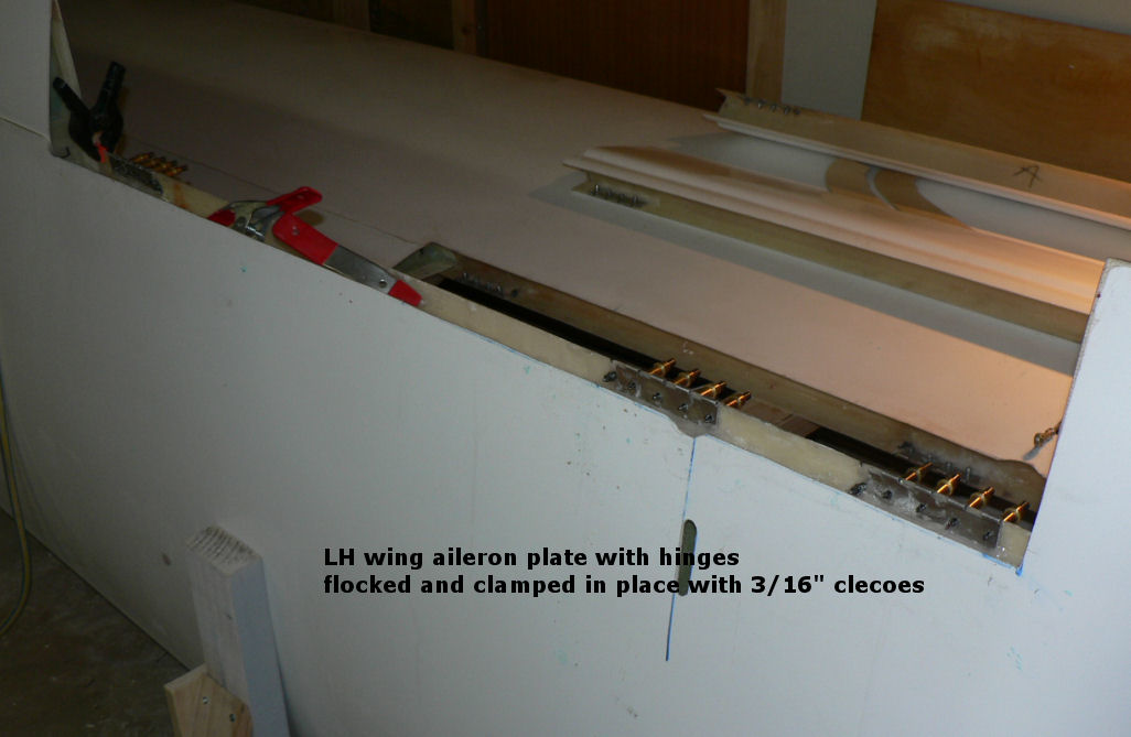
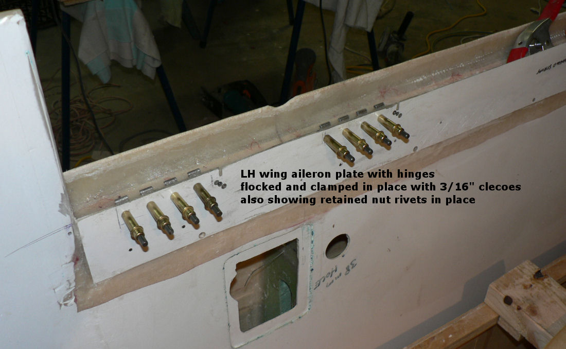
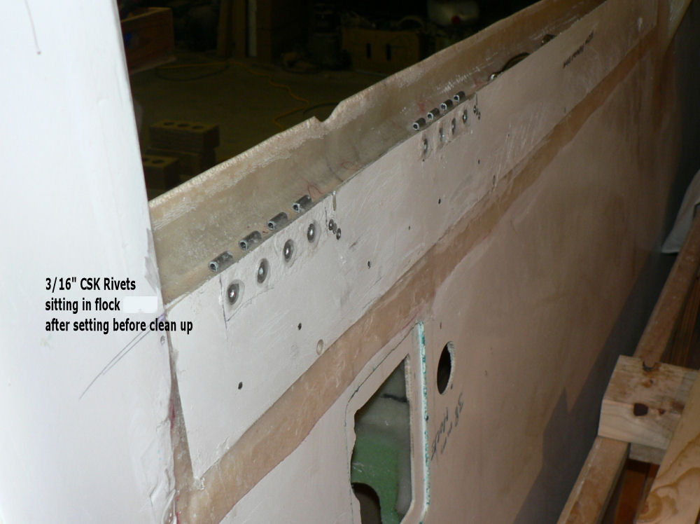
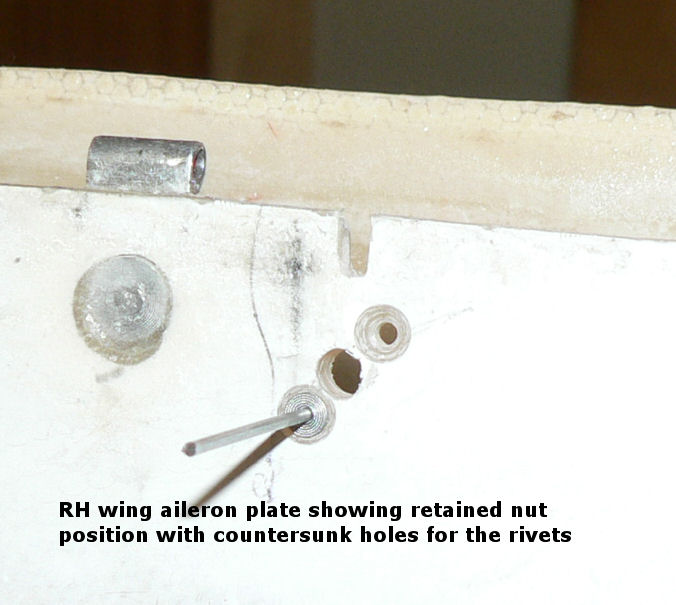
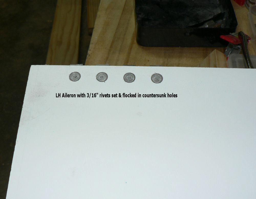
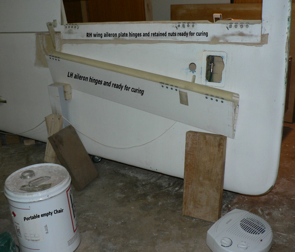
23-06-2007 Remove 5/32" clecoes from LH aileron hinges - drill aileron holes out to 3/16". Countersink 3/16" holes using microstop - clean up with acetone Prime holes with epoxy & fill with flock. Fit 3/16" rivets & flock into LH aileron & set rivets with rivet gun. Remove 5/32" clecoes from RH aileron plate hinges - drill plate holes out to 3/16". Countersink 3/16" holes using microstop - clean up with acetone Prime holes with epoxy & fill with flock. Fit 3/16" rivets & flock into RH aileron plate & set rivets with rivet gun. Prefit retained nuts for hinge safeties into RH wing aileron plate. Flock & rivet retained nuts in place. Setup LH wing aileron & RH wing aileron plate area for curing. [ATTACH]2371[/ATTACH] [ATTACH]2372[/ATTACH] [ATTACH]2373[/ATTACH] [ATTACH]2374[/ATTACH] [ATTACH]2375[/ATTACH] [ATTACH]2376[/ATTACH]
-
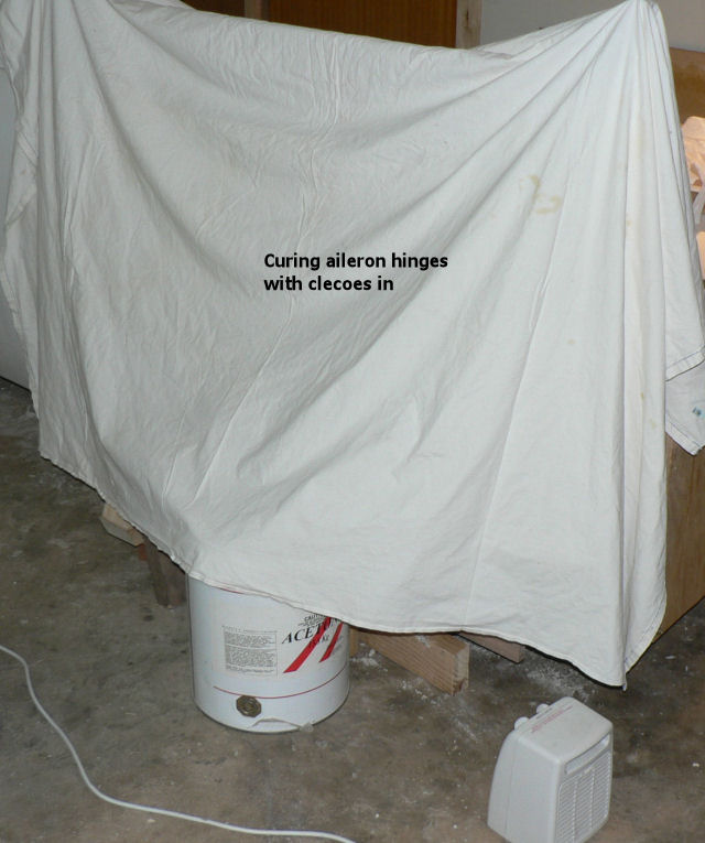
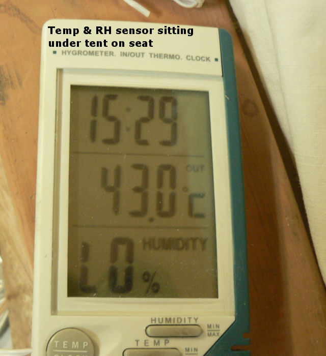
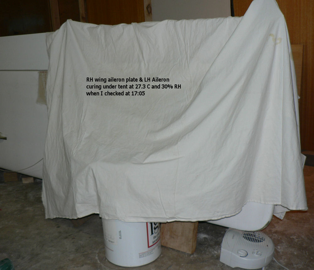
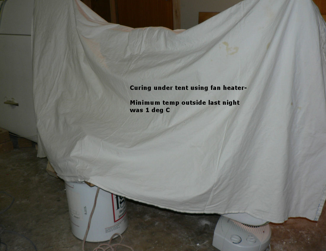
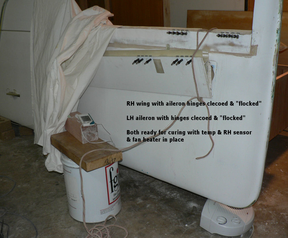
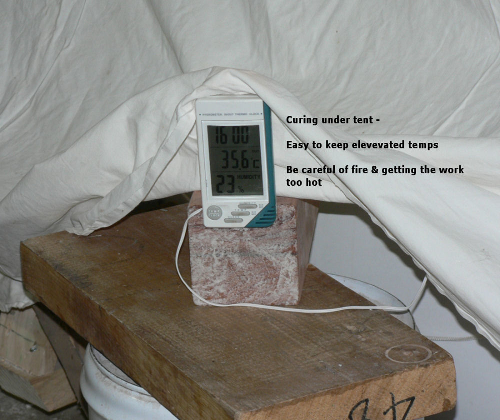
21-06-2007 "Flocked" (epoxy/flock) the aileron hinges back onto the aileron plate for the RH wing. The hinges on the aileron for RH wing were are still OK. The RH aileron was tried for ease of attachment before removing aileron and allowing RH aileron plate hinges to set. Flocked the LH aileron hinges and clamped with clecoes. Prefitted aileron onto the LH wing to check alignment of hinges on assembly. LH wing aileron plate hinges are only clamped in place with clecoes. Removed aileron from LH wing to allow flock under aileron hinges to cure. Erected tent over items to be cured. See effect on temperature and Relative Humidity. [ATTACH]2363[/ATTACH] [ATTACH]2362[/ATTACH] [ATTACH]2364[/ATTACH]
-
21-06-2007 Decided to remount RH wing aileron for better alignment with flap & wing tip. Used heat gun to soften the epoxy under and around the hinge halves on the aileron plate after drilling out the rivets in the aileron hinges. The heat makes it very easy to remove the hinges by prising them out easily using the blade of a screwdriver underneath the bottom edge and also makes it easy to remove unwanted epoxy/flock from around the hinge mounting site. Trimmed aileron plate for better fit and alignment. Both LH & RH aileron sites are prepared for epoxy/flock of the hinges by sanding and cleaning with acetone. Prefitted plate hinges using 5/32" clecoes in 3/16" hinge holes requires a 5/32" washer to retain the clecoe. The effect of the heat gun on reducing the stiffness of composite fibreglass horns & plate is a stark reminder of the Jabiru owners manual instruction not to fly when the temperature is over 40 degrees Centigrade 20-06-2007 Used a paint heat gun on LOW to soften the aileron plate to improve alignment between aileron LH wing to align aileron plate & wing more accurately. A high setting on the heat gun can result in burning the surface before the heat has a chance to conduct through a thick section. At this stage hinges only prefitted with 5/32" clecoes.
-
19-06-2007 Trimmed reo cloth on aileron plate Trimmed aileron to fit available slot between flap & wing tip. Mark position for three hinges on the aileron & drill 5/32" Pre-fit three hinges on the aileron using 5/32" clecoes with a 5/32" washer behind the hinge as the hinge holes are 3/16". Using the aileron with clecoed hinges complete attached as a template mark & drill 5/32" the the wing hinge positions Pull the hinge pins and clecoe the wing half of the aileron hinges into positon on the wing. Mark & cut slots for the hinge pins. Drill starter holes through the wing in the marked position for the aileron cable push pull rod end. Cut the aileron cable slot out useing slotting drill in a drill or a Dremel Tool. The Dremel has a guide with depth control to make a better job of it. Use flat & round coarse files to dress the slot. Dress the top edge of the wing in the aileron slot to get full up movement of the aileron. Ensure a hinge pin thickness clearance between the aileron plate and the aileron bottom leading edge to allow full down movement of the aileron. [ATTACH]2352[/ATTACH] [ATTACH]2353[/ATTACH] [ATTACH]2354[/ATTACH] [ATTACH]2355[/ATTACH] [ATTACH]2356[/ATTACH] 1. Check aileron down limit OK using Jabiru template. 2. Check up limit OK using Jabiru template. 3. Clecoes & aileron full up 4. Aileron full down 5. Aileron horn & slot for cable access