Ross
-
Posts
729 -
Joined
-
Last visited
Content Type
Profiles
Forums
Gallery
Downloads
Blogs
Events
Store
Aircraft
Resources
Tutorials
Articles
Classifieds
Movies
Books
Community Map
Quizzes
Videos Directory
Everything posted by Ross
-
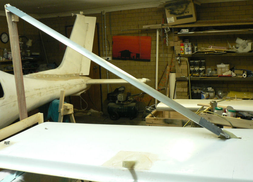
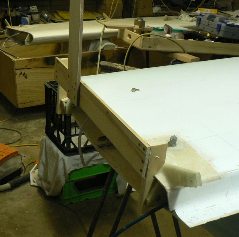
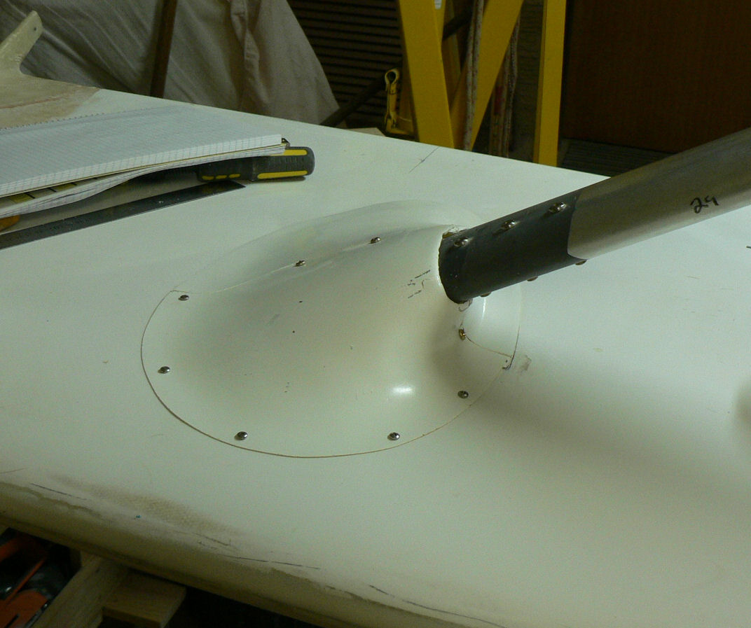
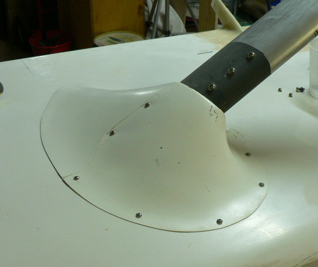
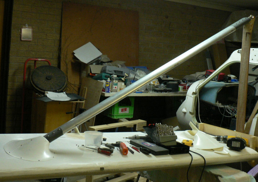
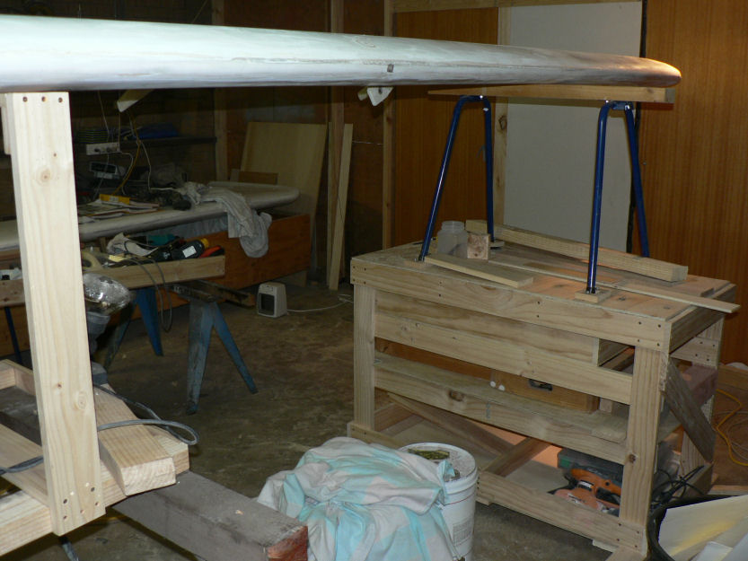
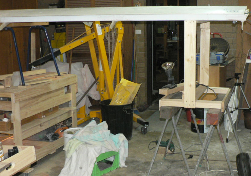
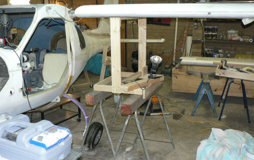
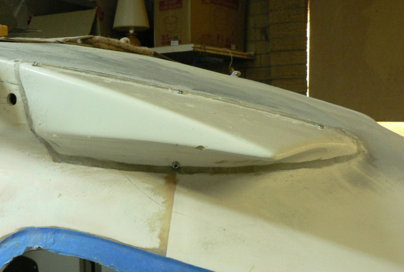
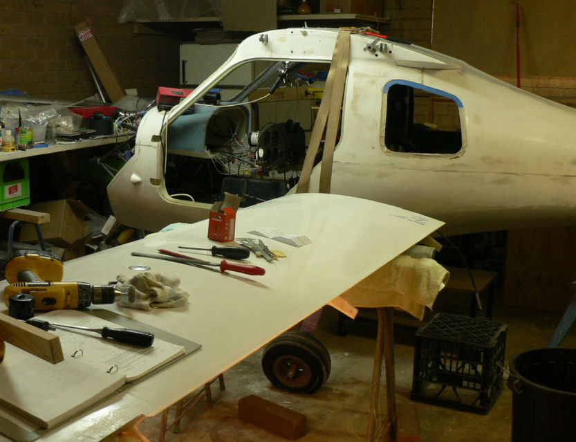
14-09-2007 Made up a stand to hold the inboard end of the strut. It is more work but it enables me to work on the fairing without mounting the wing on the A/C and do not have to work under the wing. Pre-fitted the LH wing upper strut fairing & screwed the leading edge half in place with self tappers - no fuel tank under this part. Put some retained nuts in the overlap join area of the two halves. [ATTACH]3618.vB[/ATTACH][ATTACH]3619.vB[/ATTACH][ATTACH]3620.vB[/ATTACH][ATTACH]3621.vB[/ATTACH][ATTACH]3622.vB[/ATTACH] Should be able to pre-fit the the other fairing on the RH wing tomorrow & prepare and flock both to their respective wings. The stand will have to be converted for use on the other wing.

-
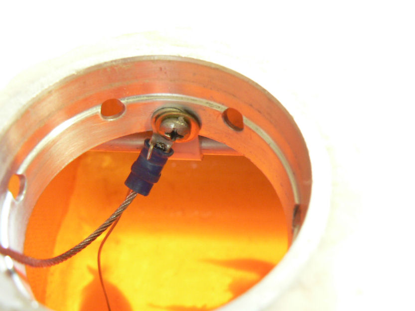
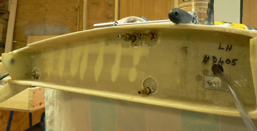
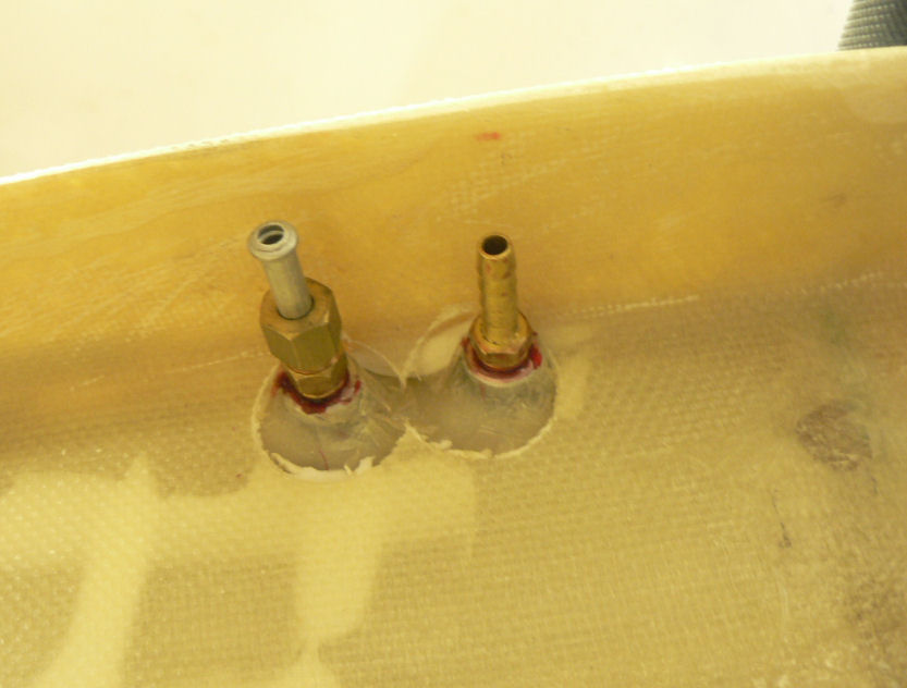
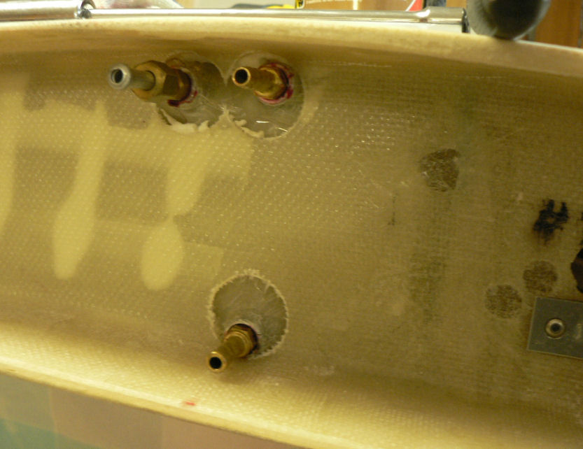
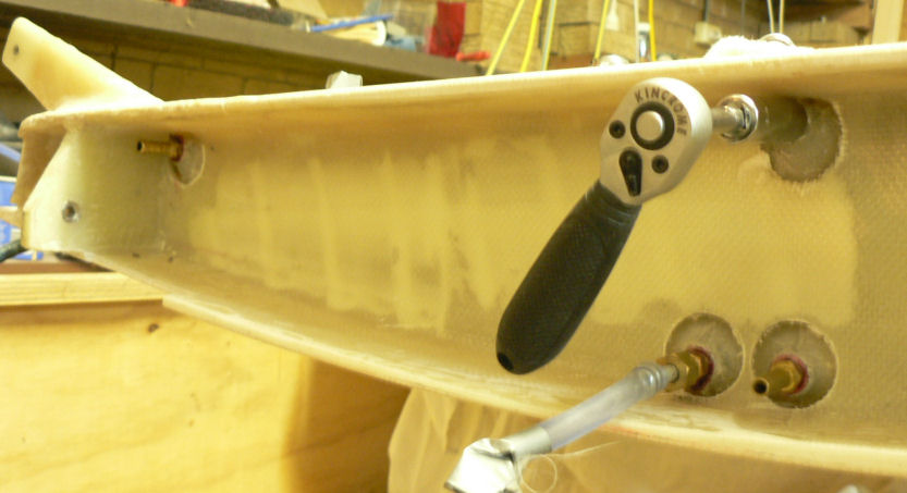
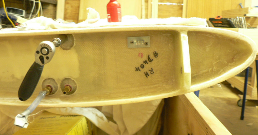
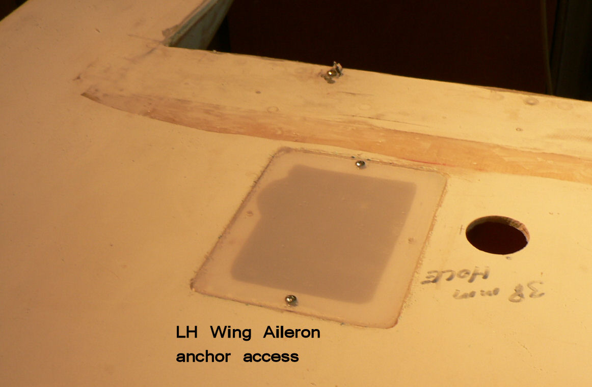
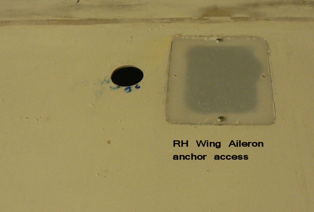
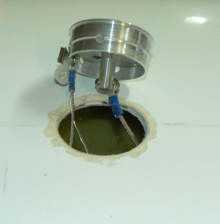
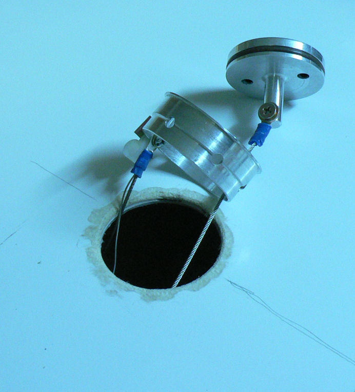
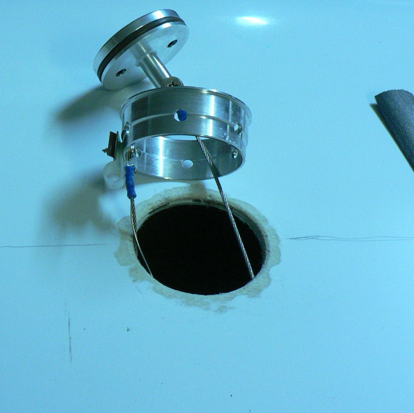
13-09-2007 Installed all fuel fitting in the LH & RH wing roots with Loctite 262 on their threads. The Quick Drains have not been done as a bit of flushing will be done later through them to reduce any initial load on the finger filters. Made sure all fuel fittings are sealed up with tape and or tubing. Removed SS screws from LH fuse to wing & flap fairing. Made up extra wing stand to facilitate fitting wing to A/C. Enlarged holes for stall warning into fuselage. Enlarged holes for fuel lines into cabin. Fitted internal breather pipe to LH wing tank and adjusted length to suit. It is slightly different from the other side. Pre-fitted aileron cable anchor inspection window to both wings. First pic is a view through tank filler on LH wing tank showing earth strap from filler cap, attach point on filler body, earth wire descending into tank, and part of the LH wing tank internal breather tube anchored on the filler body. The lght shown below is sitting on the floor under the wing providing the light inside the wing. [ATTACH]3605.vB[/ATTACH][ATTACH]3606.vB[/ATTACH][ATTACH]3607.vB[/ATTACH][ATTACH]3608.vB[/ATTACH] Some of the fittings were too close to the wing skin to use a tube spanner or a ring spanner. [ATTACH]3609.vB[/ATTACH][ATTACH]3610.vB[/ATTACH][ATTACH]3611.vB[/ATTACH][ATTACH]3612.vB[/ATTACH] [ATTACH]3614.vB[/ATTACH] [ATTACH]3613.vB[/ATTACH] The second Quick drain body installation was a much neater job with a bit more space available. [ATTACH]3617.vB[/ATTACH][ATTACH]3615.vB[/ATTACH][ATTACH]3616.vB[/ATTACH] Flood light sitting on bench was used to inspect inside of wing by placing it under the wing and looking at shadows before painting with undercoat.
-
Hi Geoff If those pillar valves were used to "control" the fuel flow the tanks are still connected via the so called breather pipe across the top which is also connected to the header tank and does not have any valves in it - anything could happen! I personally think that breather pipe is part of the reason for the moving fuel. There must be slight differences in the air pressure whether it be above or below the static air pressure in each fuel tank due to its own little breather in the filler caps. So with a different air pressure in each tank fuel transfers from one side to the other via the tubing up the pillars. But the long breather pipes in the tanks should equalise the pressures provided they are full of air. But they could be full of fuel or air or any combination in between. So any restriction of equalising air flow in the breather pipe due to there being any fuel in it will result in a flow of fuel from one tank to the other via the tube down each pillar tp the Y piece in the centre of the cabin. If the tanks are filled to the brim or the aircraft is flown out of balance the internal tank breather tubes will get some fuel in them thus producing some sort of fuel flow lock in the breather tubes as the inboard end of the connecting system where it goes across the cabin ceiling could have an air lock in it due to the dihedral angles of the wing. Once the aircraft is parked on level ground and left the tanks would eventually equalise again as the air pressure on the fuel in each tank would be atmospheric pressure and equal. So the only thing to move the fuel would be gravity due to the difference in height above the ground (assuming the aircraft is also level) of the fuel in each tank. Well that is my theory. Regards
-
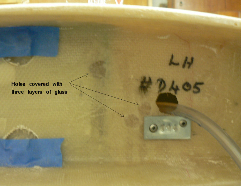
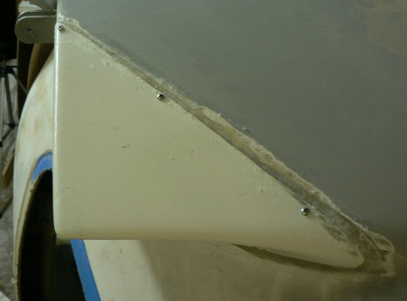
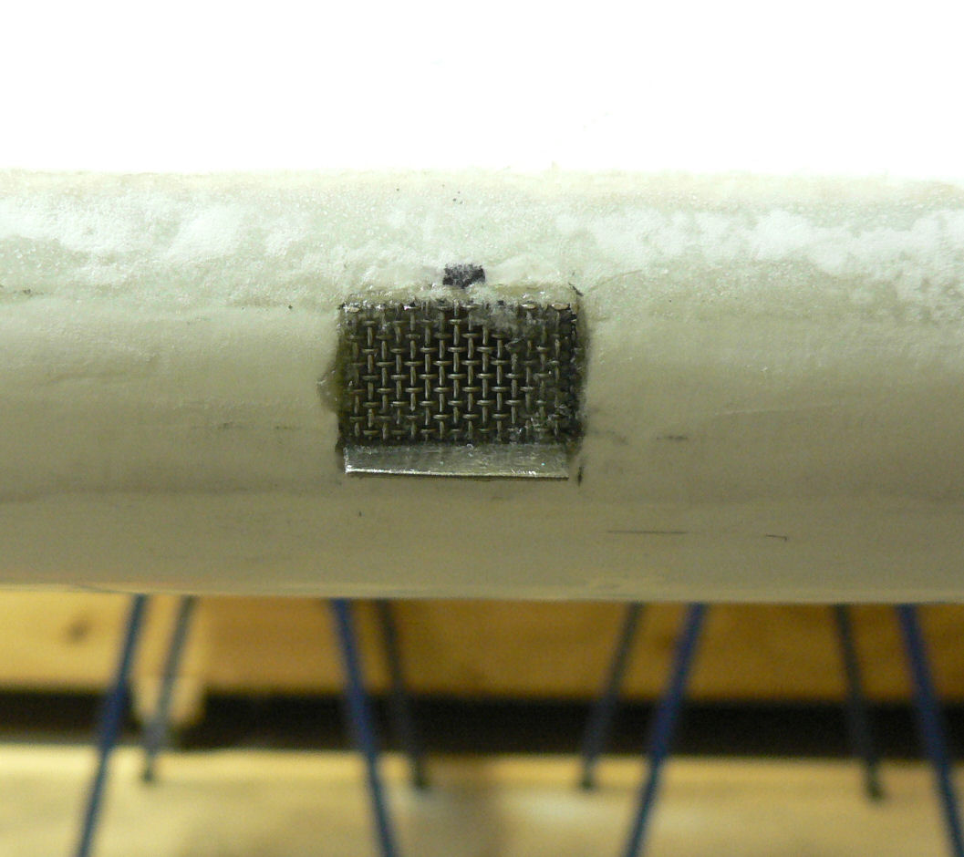
12-09-2007 Mixed a small batch of epoxy. I weigh it on an old set of post office scales. I use 5/16" nuts as mass units. So my smallest mix is 3 nuts of Resin plus 1 nut of Hardner. I had bought 50 nuts which I reserve for this job! So 50 divided by four does not go evenly! Brushed some epoxy onto the surface around the unwanted holes and applied a small dry "glass" patch with a bit of overlap. Spread some more epoxy onto the glass with the brush on top of the patch until it is soaked with epoxy. Repeated with another couple of layers. [ATTACH]3595.vB[/ATTACH] Patching the unwanted holes near the stall warning suction tube. ******************************** Attached the fairing from fuselage to LH wing. Gave all surfaces of the fairing and the fuselage to be epoxied a rub down with the emery cloth wheel in the hand drill. Cleaned all surfaces to be epoxied and flocked with Acetone. Mixed a batch of epoxy to pretreat the surfaces to be flocked together. Pretreated all surfaces to be stuck together with epoxy. Mixed the remaining epoxy with cotton flock and when ready applied it to the surfaces to be attached. This is flock batch # 122 a sample of which has been saved in a waxed medicine measure about 2 or 3 mls. After it cures it will be removed and marked with its sample number with a permanent marker and put in storage in plastic screw top honey jars with other samples. The sample numbers in the jars are marked on the outside of each the jar. Applied the self tappers to hold the fairing in place until the flock is cured. The fairing was lined up in an earlier session with the wing & flaps and drilled and self tappers applied to keep it in place. [ATTACH]3596.vB[/ATTACH][ATTACH]3597.vB[/ATTACH] The fairing will need more filling and will also be cleaned up when closer to curing or after curing. It may also be moved a bit more if necessary by using some heat from the hot air gun before trying to change things.
-
11-09-2007 Managed to get the stall warning fitted in the LH wing leading edge. A suck on it after it cured and it made that sound that controllers hear when they call up pilots who are rounding out without their undercarriage being lowered. [ATTACH]3593.vB[/ATTACH] [ATTACH]3594.vB[/ATTACH] Still need to patch up a few superfluous holes.
-
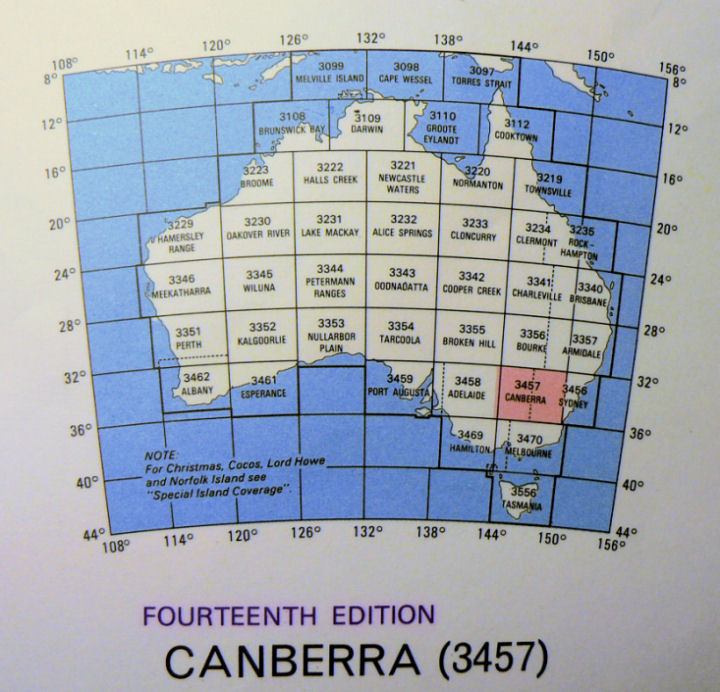
Hi Ben WAC or World Aeronautical Charts are charts (maps) specifically designed for Visual Flight Flying. They have things on them that are important to pilots like the heights of TV towers and mountains and the location of these and aerodromes and major roads, railway lines and out our way wheat silos at railway stations etc etc. Lakes and rivers are easy to see from the air so even if they have no water in them are still very prominent so feature on the charts as well. The charts can be bought treated so that you can write on them and rub the tracks & notes out without permanently marking the map. See the index of all Australian WACharts below. [ATTACH]3590.vB[/ATTACH] The series covers the whole of Australia with each chart covering 6 degrees from East to West and 4 degrees from North to South. Regards
-
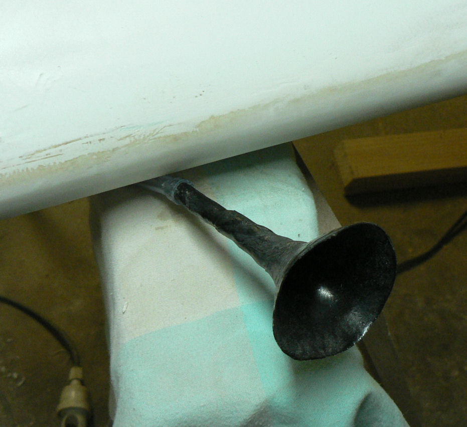
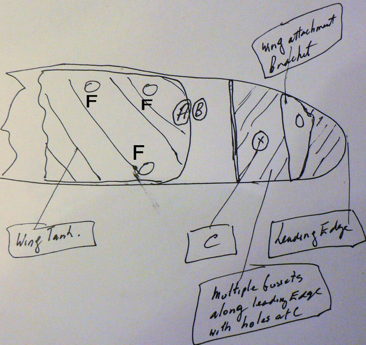
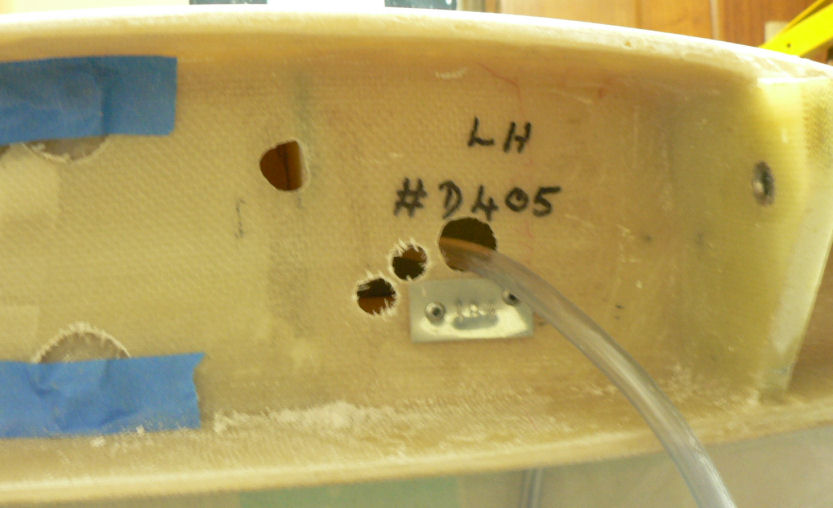
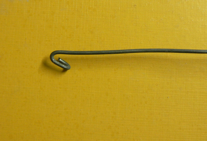
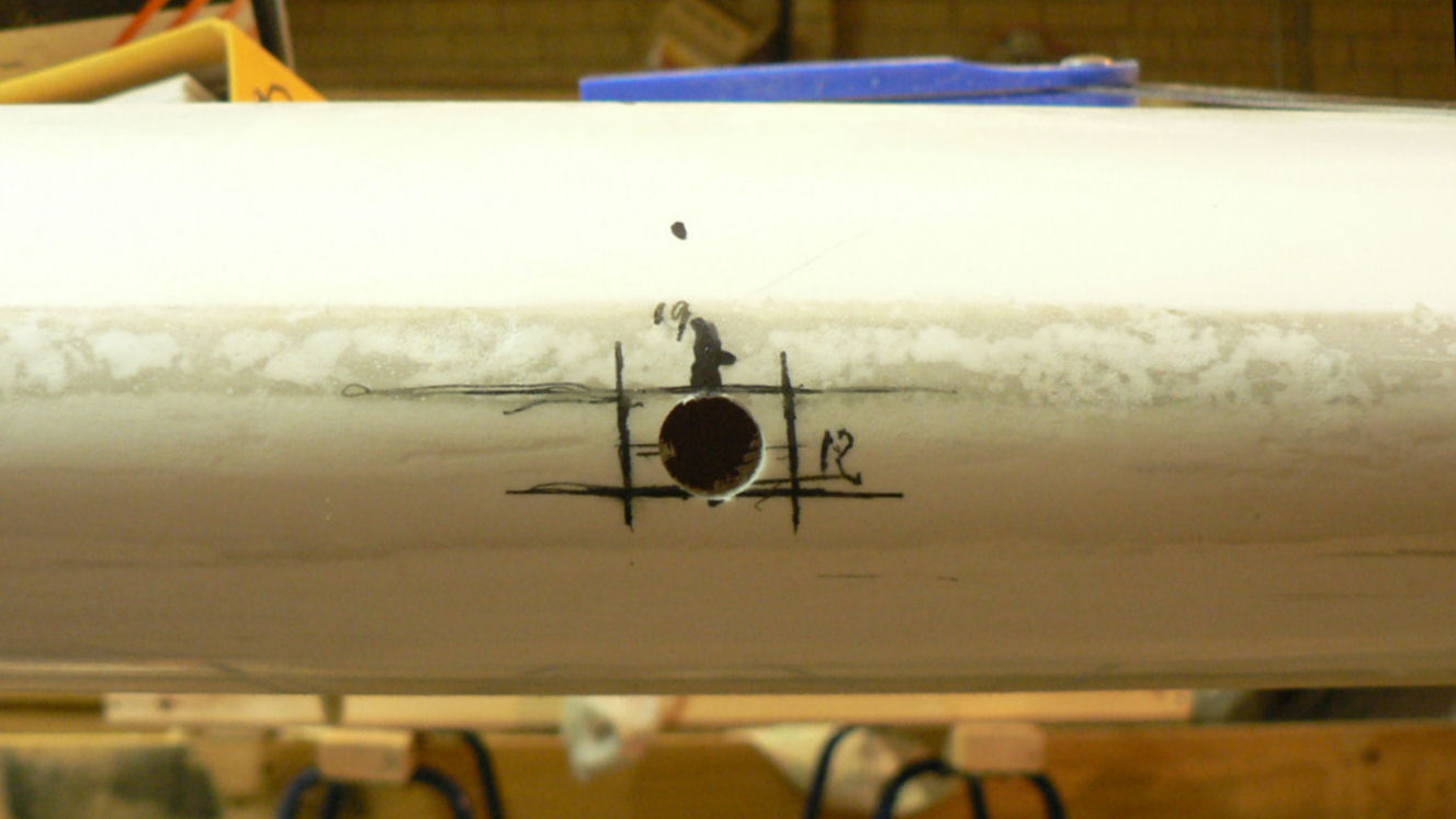
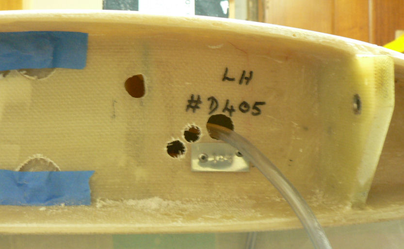
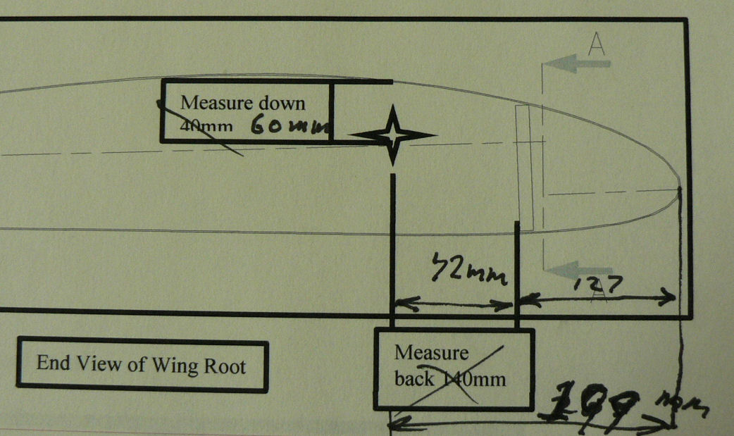
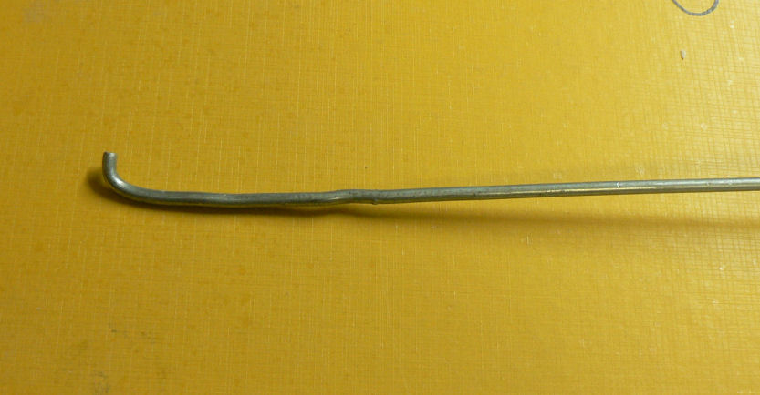
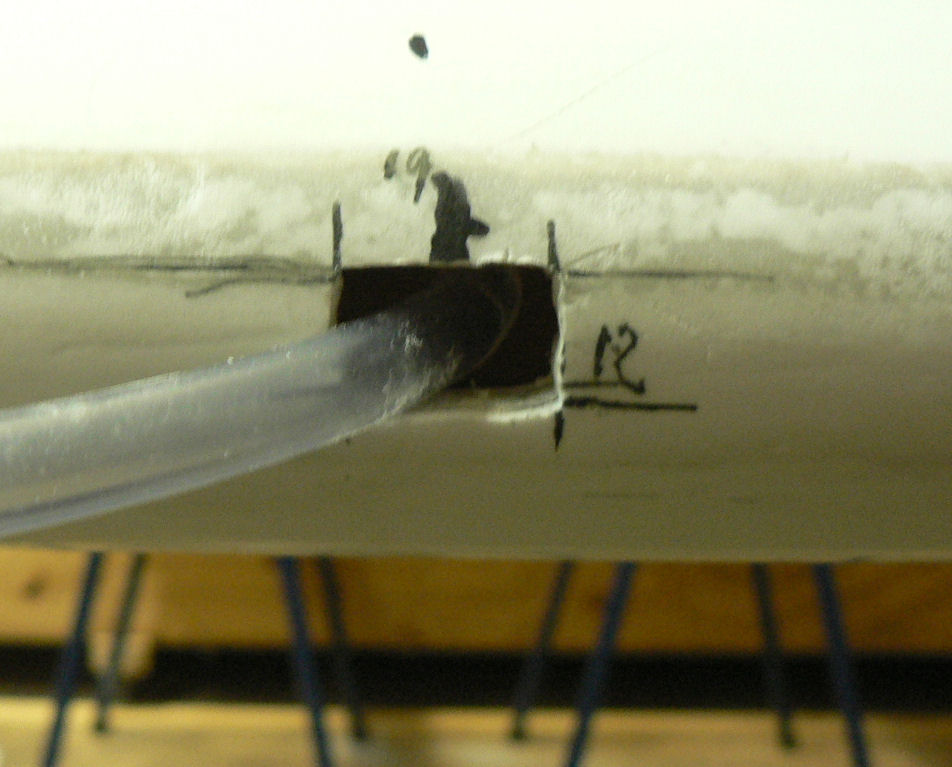
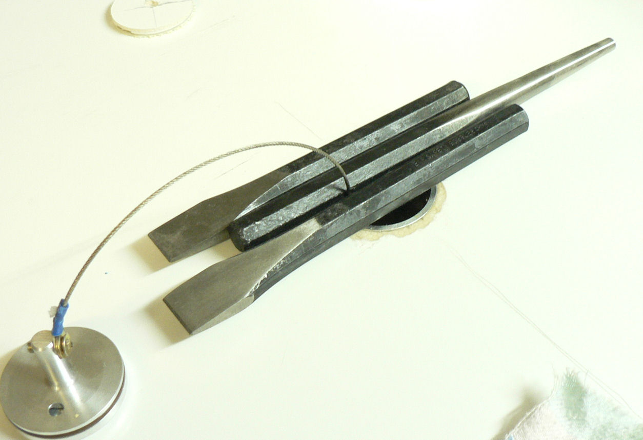
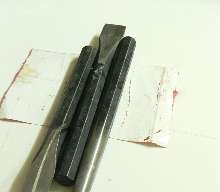
9-09-2007 Went to Narrandera for the monthly barbecue and managed to have a short flight in Wall's J230c, a lovely aeroplane and very nice to fly. It proved I needed more flying. 10-09-2007 Installing stall warning fitting in left wing leading edge. I will start this off with a very rough freehand sketch that took a full two minutes to prepare. [ATTACH]3581.vB[/ATTACH] This rough sketch represents the inboard end elevation of the LH wing area and the sectional view inside the wing probably as far as where the stall warning will be installed. If I had followed the installation instruction I would have drilled a hole through the end of the wing and the tank in about point A on the sketch. I put a strong light under the wing and decided that drilling a hole at A was not a good idea followed by probing with a piece of wire through the fuel tappings for the sight gauge verifying that. So hole B was the result which only just missed the tank. So I fed a piece of wire through hole B which was able to get into the wing past the stall warning position. The wire could not be seen through the hole drilled through the leading edge for the stall warning sensor at 1215 mm from the wing root. So there was no access to the Leading edge from hole B. Via the next two smaller unlabelled holes it was discovered that there were multiple gussets along the leading edge with large holes in line through them. With a final hole at C, it was possible to insert a piece of wire or a rod with a bend in it and a folded piece on the end over which was forced one end of the stall warning 8 mm tube. Once the tube was led by the wire past the stall warning position the tube was pulled back lightly so the wire disengaged and the wire was then pulled out. Then a heavier short wire with a right angle end was used to retrieve the plastic tube through the hole cut out and ready to take the stall warning sensor end. [ATTACH]3581.vB[/ATTACH][ATTACH]3582.vB[/ATTACH][ATTACH]3583.vB[/ATTACH][ATTACH]3584.vB[/ATTACH] I have shown a modified version of part the J160 stall warning drawings to show the eventual position of the hole that I cut for the stall warning tube. I do not know if this applies to later kits. [ATTACH]3585.vB[/ATTACH][ATTACH]3586.vB[/ATTACH][ATTACH]3587.vB[/ATTACH][ATTACH]3588.vB[/ATTACH] The final straw was to find that the spring loaded clamps supplied to clamp the plastic tubing on the funnel shaped sensor was much too large in diameter. [ATTACH]3589.vB[/ATTACH] A quick trip around Leeton starting at about 17:20 hrs to four garages, a shop specialising in tools and equipment for all sorts of trades, and a Repco like shop failed to find a spring loaded clamp. I just missed the lawnmower shop/workshop which would probably be the best bet.
-
Here's a clue of about what our older languages thinks of left and right handed people. The Latin word for right handed was dextra The Latin word for left was sinistra Regards
-
Hi Ross Happy birthday. A thoughtful gift from your well meaning sister. But was it an authorised mod from the original design? It reminds me of another such event where Glen McWilliam's wife took a pile of rocks which normally lay about on a hillside somewhere, to the Leeton Gliding Club lawn and turned it into an about 1960 built ES52 Mark IV Kookaburra, the type of rag and wood glider flown by the club at the time of the incident. It has since been discovered many years later (they have passed on) that she had not had the appropriate paperwork for the new arrangement of the rocks so the model was destroyed! (It got in the road of the lawnmower.) May you have many more memorable birthdays. Regards
-
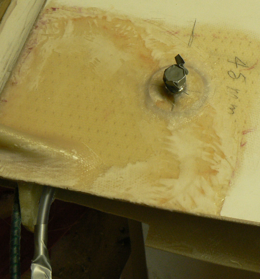
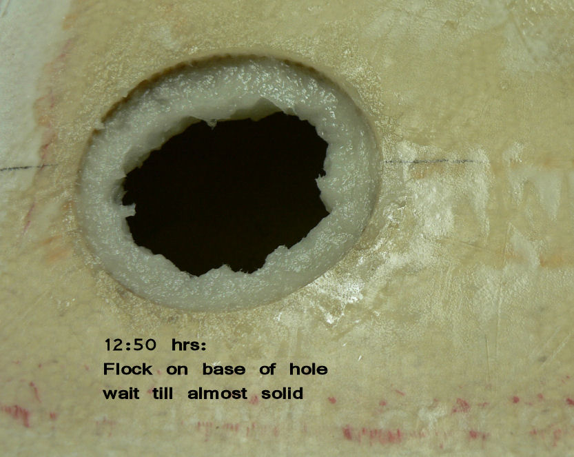
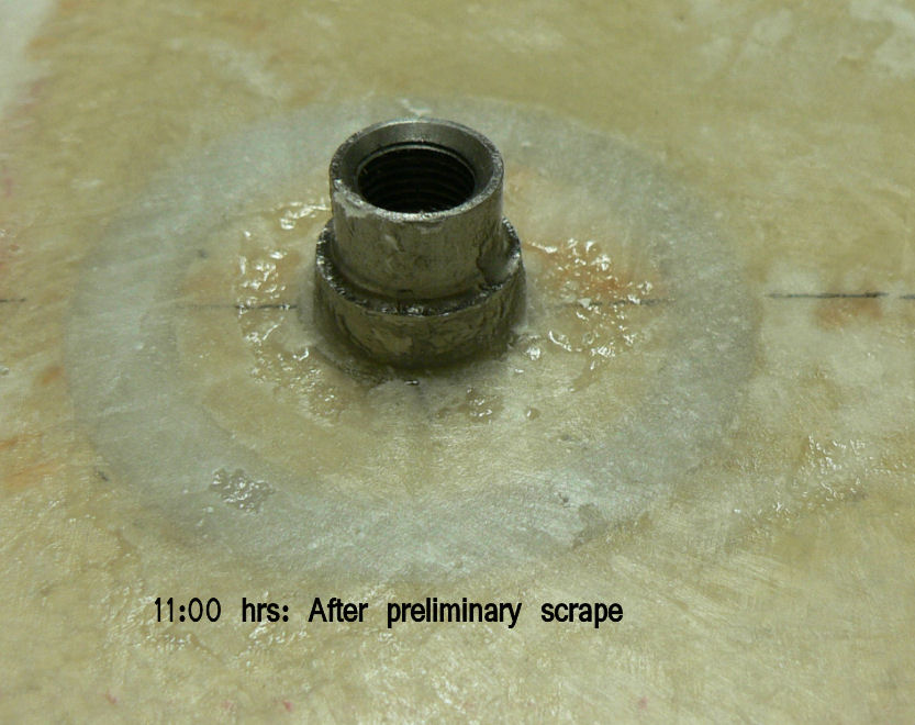
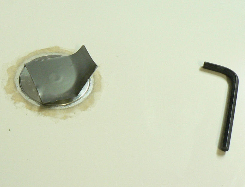
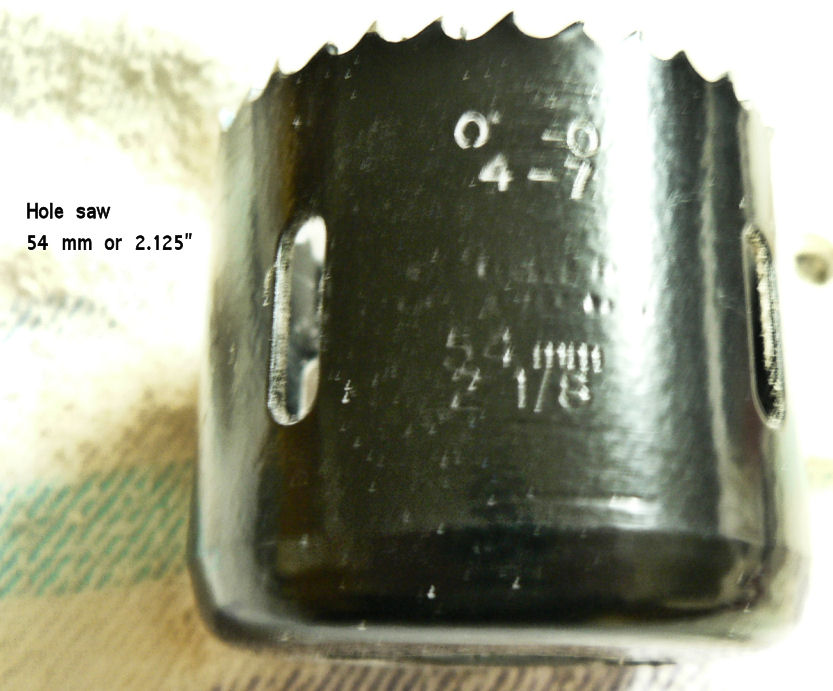
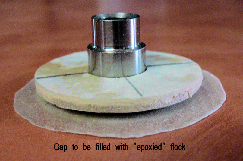
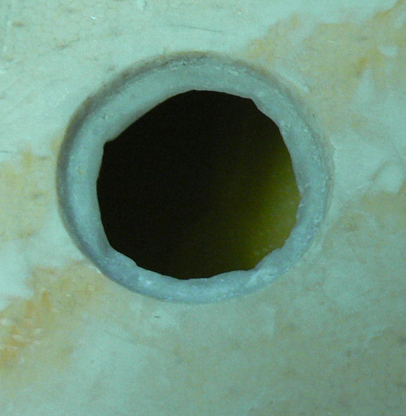
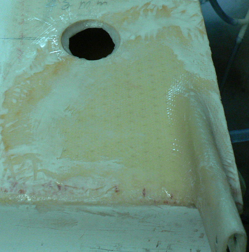
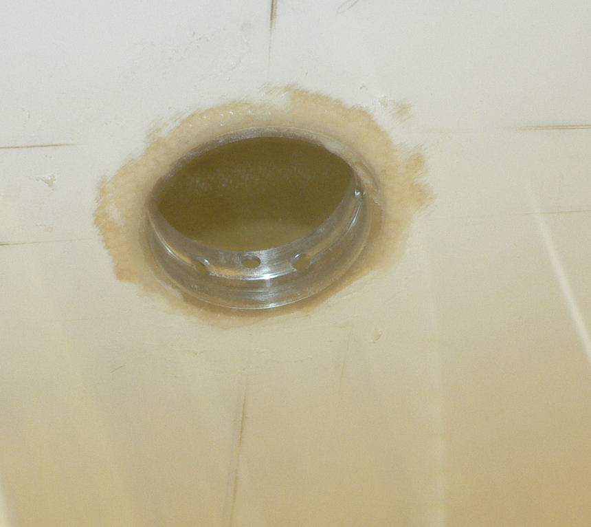
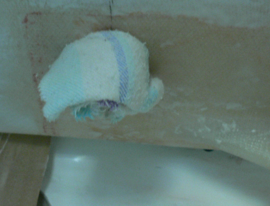
8-09-2007: LH wing Quick drain continued: Hole already exists as 45 mm right intoo the tank. Inserted a false centre in the 45 mm hole and holesawed it out to 54 mm taking care not to go through the tank skin again. Vacuumed out the waste with the filler cap removed and a rough seal around around the suction hose into the quick drain hole. Cleaned out material in the hole on top of the tank skin using the heat gun and a chisel. Made up epoxy & primed the quick drain hole hole & surrounds. Epoxied fibreglass cloth to the circular tank skin that was cut out at the quick drain hole and sat it on the bench to semi-cure under a brick and some peel cloth. Mixed up epoxy with flock to put a base in the quick drain hole hole to support the cut out tank skin. Had to wait till this was almost hard so that it could be formed to support the tank piece. [ATTACH]3558.vB[/ATTACH][ATTACH]3559.vB[/ATTACH][ATTACH]3560.vB[/ATTACH][ATTACH]3561.vB[/ATTACH][ATTACH]3562.vB[/ATTACH] [ATTACH]3563.vB[/ATTACH][ATTACH]3564.vB[/ATTACH][ATTACH]3565.vB[/ATTACH][ATTACH]3566.vB[/ATTACH][ATTACH]3567.vB[/ATTACH][ATTACH]3568.vB[/ATTACH] Forgot to take a photo of it when it was ready to flock the quick drain body assembly in place. Prepared the parts by sanding, cleaning with acetone, treating with epoxy and assembling with a layer of fairly liquid flock to make sure that it gets into all the crevices. Care was taken to push some flock into the gap where it existed between the wing skin and the tank skin. Next morning after using the scraper. Still needs cleaning up. [ATTACH]3569.vB[/ATTACH]
-
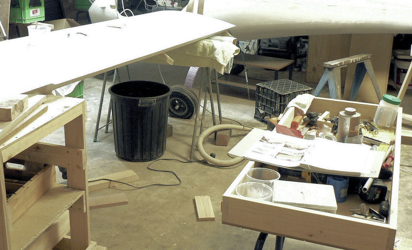
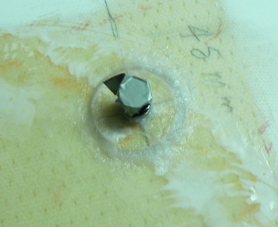
7-09-2007 Mixed epoxy for LH wing fuel filler body. 14:30 hrs Sanded fuel filler body parts and cleaned it and the mating wing hole with acetone and then primed them with epoxy. Used the remainder of the epoxy to mix with flock. When ready treated the mating surfaces again with "flock" and inserted the fuel filler body into the wing hole. Forced additional flock all around and down the side of the fuel filler body below its lip. Because of the attached earth wires the fuel filler body tended to rotate so I had to ballast it pretty well and check it a number of times until it was cured enough to resist any turning forces. I should have disconnected the earth wire to the cap and that may have helped. The fuel filler body should end up with the one hole for the self tapper that holds the breather pipe and the earth wires on the side of the filler body closest to the leading edge of the wing because that then will allow the attached breather pipe to go to the highest point of that wing tank. [ATTACH]3554.vB[/ATTACH][ATTACH]3555.vB[/ATTACH][ATTACH]3556.vB[/ATTACH] about 21:00 hrs I also made up an extra tray for tools that should allow me to keep almost all the tools off the floor and the aircraft. [ATTACH]3557.vB[/ATTACH] I also made an extra set of rails on the wheeled bench to carry that extra tray when not on a set of trestles. It would have been better to have done all the trays etc earlier - but then I did not have as many tools!
-
There is a product available that is highly absorbent that allows you to do it in your pants and not get them wet. I do not have any experience of it or ever seen it. But I have seen it advertised somewhere on an aviation site. Regards
-
Hi Brian Thanks for the tip on the paper. I keep forgetting to use peel cloth on small sections like around fittings. But I will definitely use some on the LH wing tank filler fitting small as the mess should be. The breather pipe has a unique compression fitting with no finger filter on the inside end. Basically slide the compression nut up along the pipe to the end with the flare on it. Then slide the brass compression bit on as well being carefull not to jam it. Then slide the pipe through the fitting on the end of the tank until it reaches the far end of the tank - I had to shake mine a bit up and down & sideways to eventually get to the end of the tank - it might even be temporarily stopped by the tank filler body. Once at the far end. Mark the entry end & retract the pipe 5 mm. Measure the length of pipe still outside the tank maybe about 60 mm. Pull the pipe out of the tank - allow probably about 20 to 25 mm for connecting the fuel lines to the Al tube and cut off the balance probably about 20 to 30 mm from the non flared end. Each one will be different because of how the tanks are made. Need to file a bit of a radius on the fresh cut end so that it will not jam or damage the inside of the tank. Also need to debur the cut end and make sure no small pieces of metal end up inside the tank or inside the pipe. Reinsert the pipe and when it gets to the clamp at the tank filler feed it through the plastic clamp till it is stopped by the end of the tank - retract it 5 mm and do up the clamp & fitting. When doing the RH wing breather pipe I made the mistake of not attaching the clamp to the filler neck before flocking in the fitting. I even thought that I had put the filler in 180 degrees out - turned out to be the right way round! As you can see below when doing the LH wing breather pipe I have attached the clamp & earth wires before flocking the filter into the tank and wing - a much better idea. Buying a 54 mm holesaw and using it on the LH wing tank filler hole also was much better than using the 50 mm holesaw for the filler hole which I had done for the RH tank filler. Regards
-
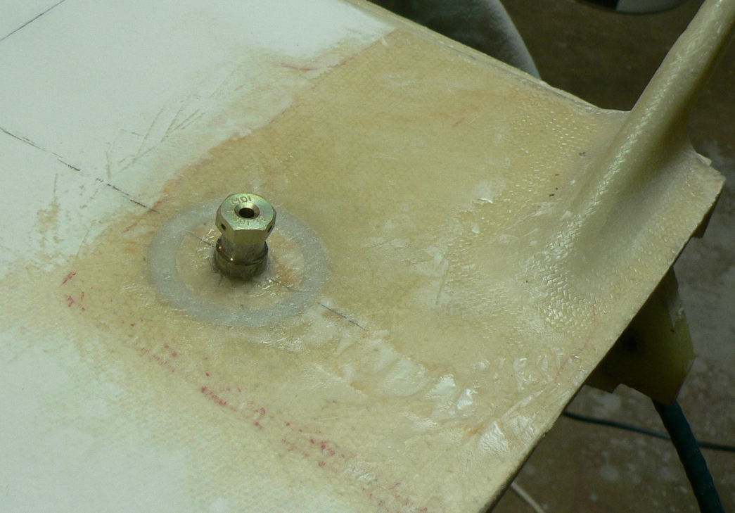
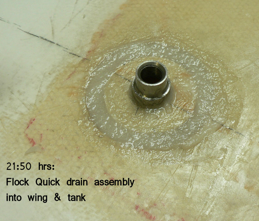
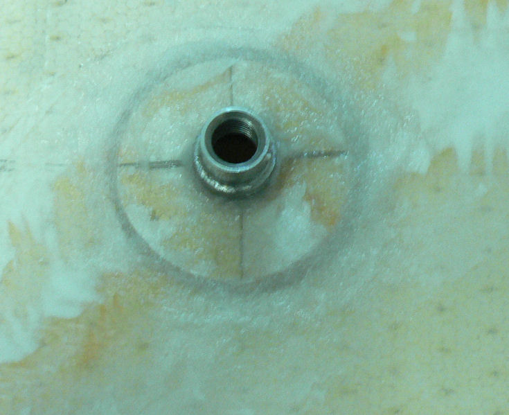
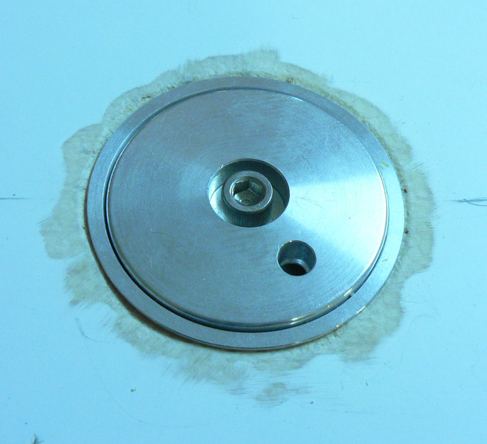
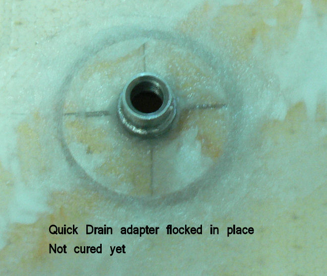
6-09-2007 RH Wing Installed the fuel cap and fuel tank earth connecting to the filler body on RH wing. Inserted the breather tube for RH tank and trimmed length to suit tank. This tube is threaded through the plastic clamp attached to the filler body. It is pushed through until it reaches the outer end of the fuel tank then retracted 5 mm. The length is adjusted to suit the tank. Screwed the quick drain valve into the adapter already flocked into the wing & tank. [ATTACH]3543.vB[/ATTACH][ATTACH]3544.vB[/ATTACH] Foregot to take photos here of the earthing & breather pipe installation. LH Wing Derigged the LH wing preparing to install the fuel filler hole. Marked the position for the fuel filler body 350 mm back from the wing leading edge and 1500 mm outboard from the inboard end of the fuel tank. This locates the filler in the top outboard end of the LH wing tank. Using the 54 mm or 2.125" holesaw cut the hole for the fuel filler body. This is the outside diameter size of the fuel filler - not 50 mm. Used the drill mounted emery cloth to remove the gelcoat off around the edge of the top of the hole. Cleaned up the loose bits in the hole. Vacuumed out the loose material near the filler hole in the tank after removing the cloth plug blocking the quick drain 45 mm hole. Assembled the fuel filler body with earth strap and tank earth wire and sat it in the filler hole. [ATTACH]3545.vB[/ATTACH][ATTACH]3546.vB[/ATTACH][ATTACH]3547.vB[/ATTACH][ATTACH]3548.vB[/ATTACH][ATTACH]3549.vB[/ATTACH] [ATTACH]3550.vB[/ATTACH][ATTACH]3551.vB[/ATTACH][ATTACH]3552.vB[/ATTACH][ATTACH]3553.vB[/ATTACH] Pieces still need to be sanded, cleaned with acetone, treated with epoxy and the hole edges then flocked into place and after curing install the LH tank breather pipe.
-
Hi Roger I could lend you my hand held multi-year old Magellan GPS 320. It is still going strong and works well in plastic aeroplanes! The interface is via RS232 at 1200 baud and it has been upgraded a couple of times. I discovered on one of the upgrades that there was mountain near Whitton NSW that was some thousands of feet AMSL. But don't worry it does not have terrain warning! Regards
-
I have heard that some North Americans use electric blankets on the floor under their car engines in their home garages. Regards
-
It sounds like a good idea to me to keep the Australian events n one place. It is taking longer & longer to sift through the news items to find incidents & accidents pertinent to Australia and see them repeated sometimes in other threads. If you want to go International then a separate thread for each country might be in order. REgards
-
Setting Flap rods on J160 Hi J160 and J160c fliers how much difference have people got in their neutral Flap settings between the LH & RH flaps after their test flights. Did you do the test flight with both set the same? Did you need to adjust your flap rods and if so how much? Thanks Regards
-
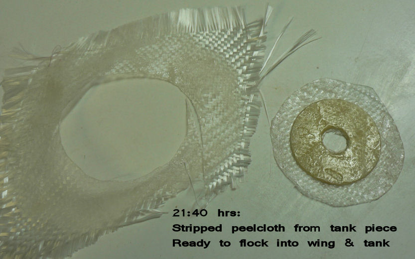
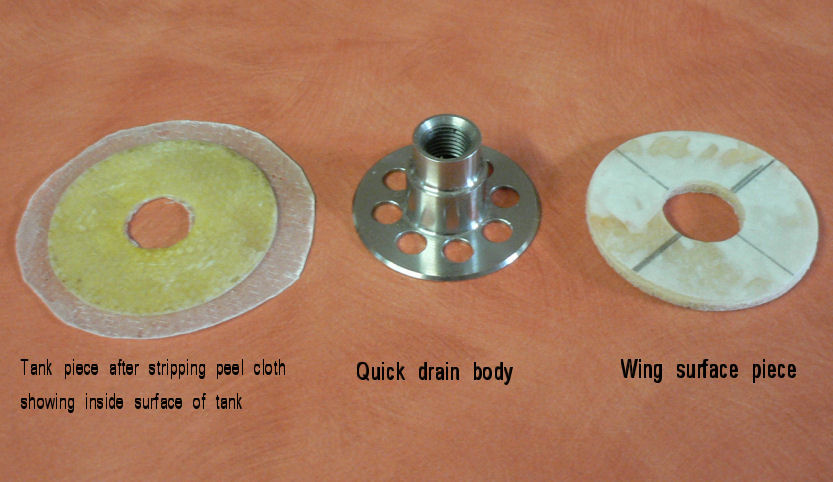
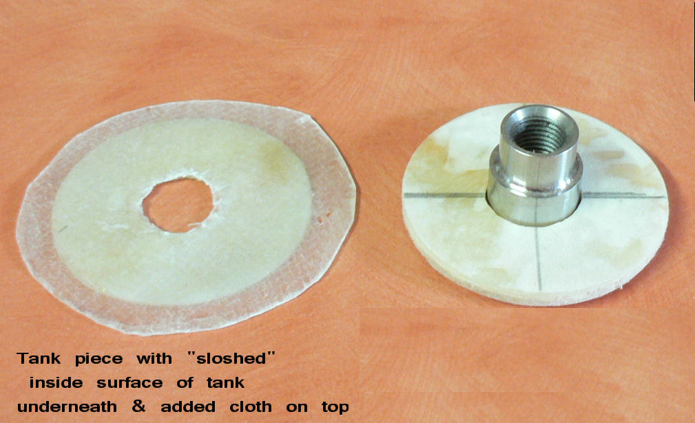
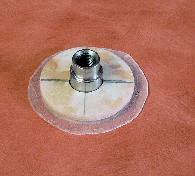
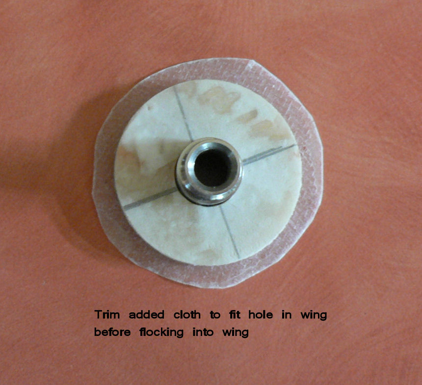
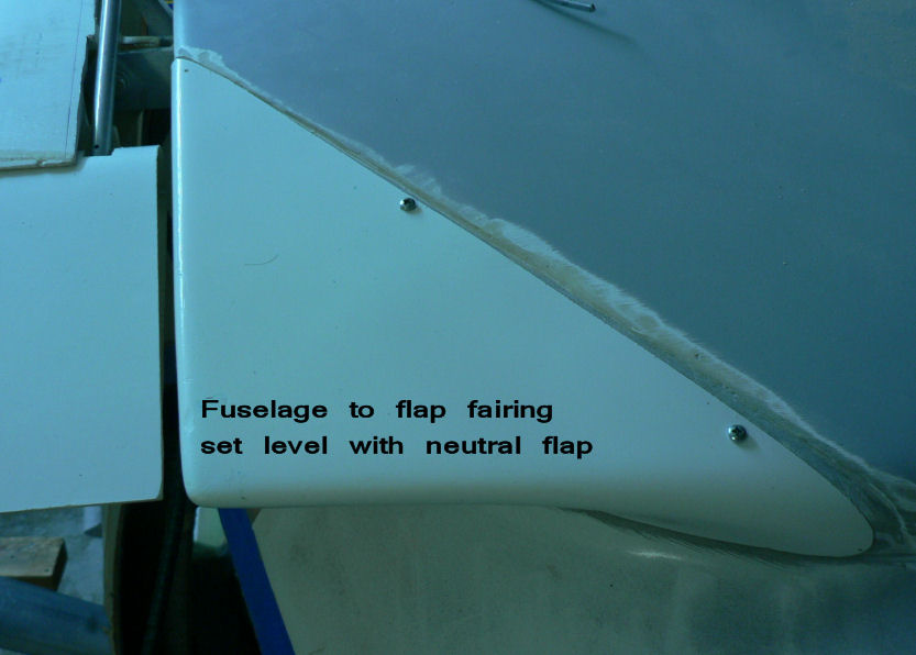
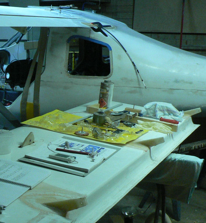
5-09-2007 The RH Wing Stripped the peel cloth from the tank piece and trimmed the added fibreglass to fit inside the 50 mm cut out. Cleaned up the quick drain hole so that the cut out tank piece will sit well down in the hole. Did not use the tool prepared yesterday to support an annulus in a hole! Sanded all the pieces to be flocked. Cleaned all surfaces with acetone. Prepared epoxy & pre-treated all the pieces with epoxy. Prepared flock by mixing flock with the already prepared epoxy. Applied flock to all pieces and sat the assembly into the tank/wing hole sitting on the epoxy ledge from last night. [ATTACH]3525.vB[/ATTACH][ATTACH]3526.vB[/ATTACH][ATTACH]3527.vB[/ATTACH][ATTACH]3528.vB[/ATTACH][ATTACH]3529.vB[/ATTACH] [ATTACH]3530.vB[/ATTACH][ATTACH]3531.vB[/ATTACH][ATTACH]3532.vB[/ATTACH][ATTACH]3533.vB[/ATTACH] At 22:10 hrs two heaters running with current temp at about 20.5 degrees C. The LH wing The bolts arrived so the flap rod for the LH wing could be rigged. At neutral flap lever setting the flap rod was adjusted so that a straight edge under the wing and flap had no gap. The fuse to flap fairing was drilled and self tappers inserted so that fairing to flap gap was 3 - 5 mm and it was set level with the flap trailing edge. [ATTACH]3534.vB[/ATTACH] Yet to be flocked in place- I would rather do it after the test flight but suppose it must be done before the first flight. Strange colours because I did not use flash to save glare and shiny spots.
-
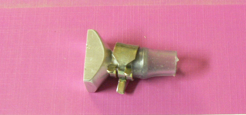
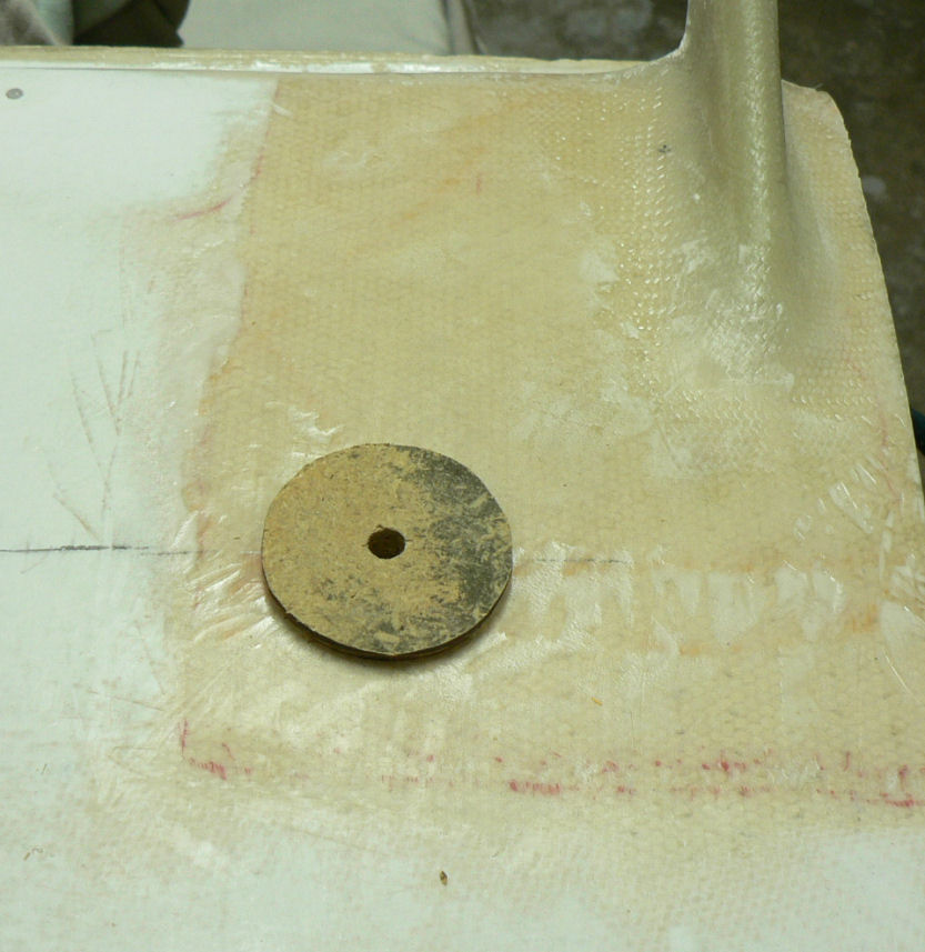
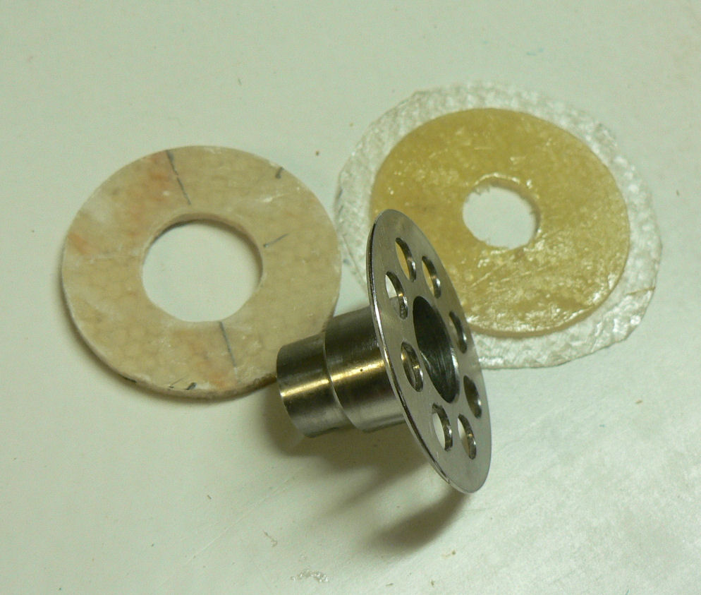
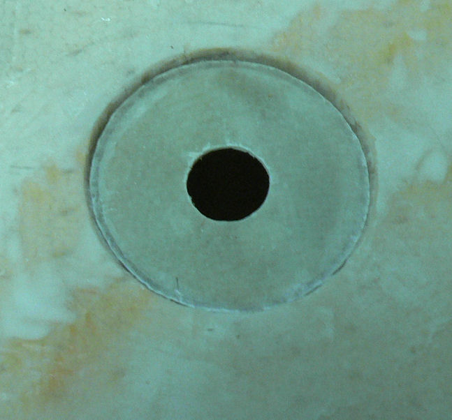
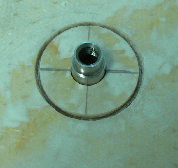
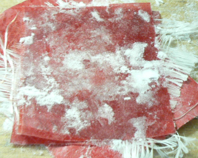
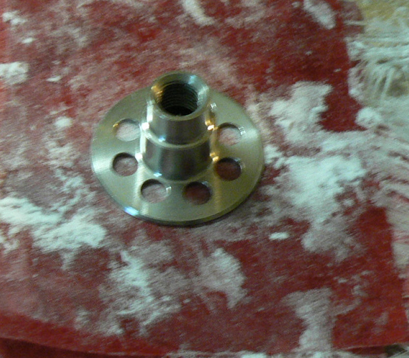
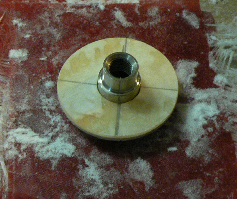
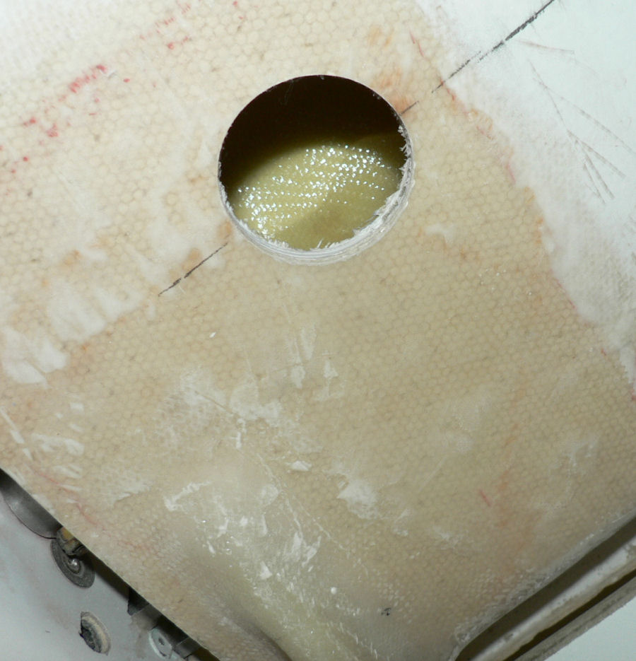
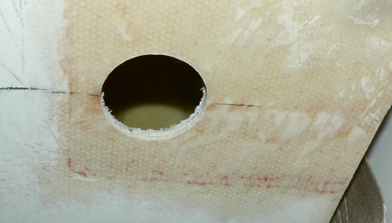
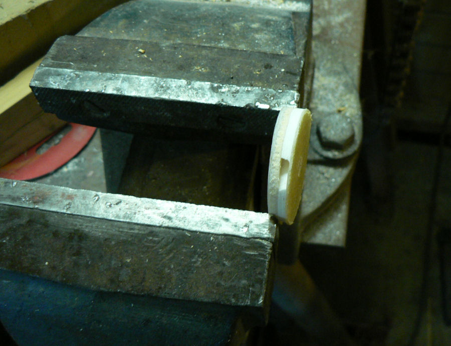
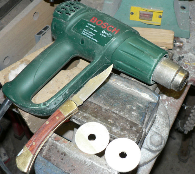
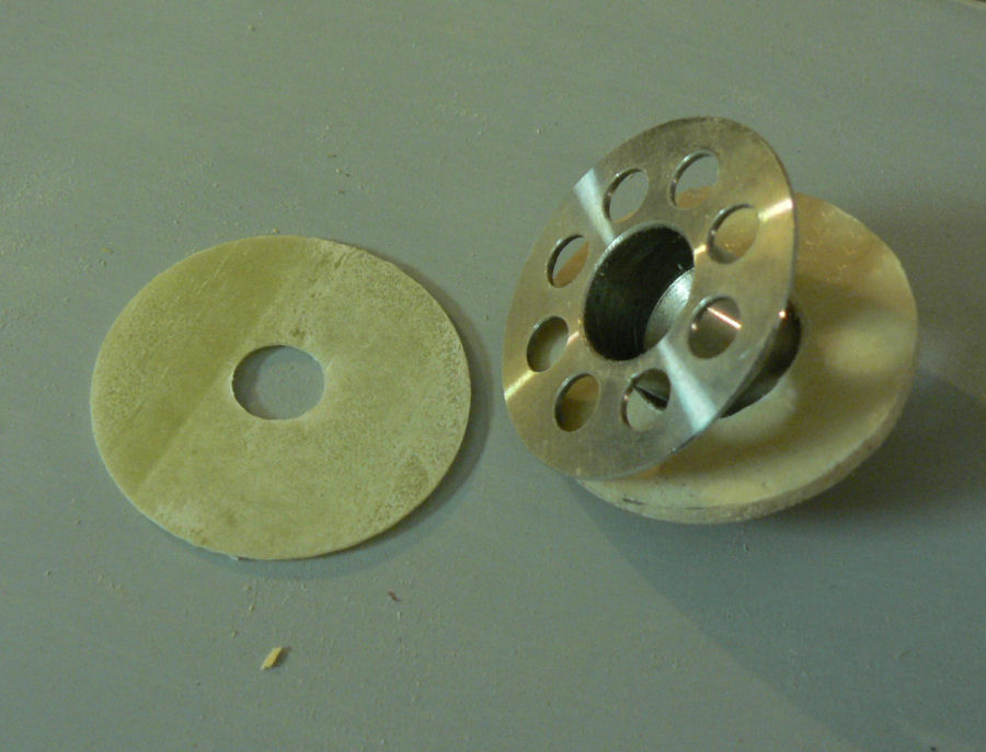
04-09-2007 Bolts will arrive today, Wednesday, presumably as my supplier had run out of one particular bolt that I ordered. Turned the RH wing upside down on the bench and hole-sawed out the quick drain hole with a 50 mm hole-saw assuming the tank and the wing would be glued together. They were glued together so there was no air gap between them. The 50 mm cut out will make it easier to reinsert the tank cut out piece and attach the fitting. It will also make it easier to use the vacuum cleaner suction hose inside the wing to remove the material from the hole saw and cleaning up the hole. A layer of flock was placed around the hole into the tank so that I can sit the cut out piece on it when it is flocked back in later on. [ATTACH]3509.vB[/ATTACH] The tank and wing piece cut out by the hole-saw were separated by heating and then splitting with a knife. The tank piece was epoxied to a piece of fibreglass cloth to prepare it for later installing. It is under the red material in the following photos. Some dry flock has been added to the outside of the red material to dry up epoxy that has gone through the material and save it sticking to the weight that was added to keep it flat and thin. [ATTACH]3510.vB[/ATTACH][ATTACH]3511.vB[/ATTACH][ATTACH]3512.vB[/ATTACH] The wing cut out piece has been drilled and filed to suit the quick drain adapter shown here above sitting on top of the quick drain adapter. [ATTACH]3513.vB[/ATTACH][ATTACH]3514.vB[/ATTACH] The last photo is showing an adapted tool to support the replaced tank piece for curing when it is replaced later. The support can be withdrawn back though the drain hole but it will have to be larger than the 3/8" specified. So it will have to be done before the quick drain adapter is flocked to the piece of replaced tank.
-
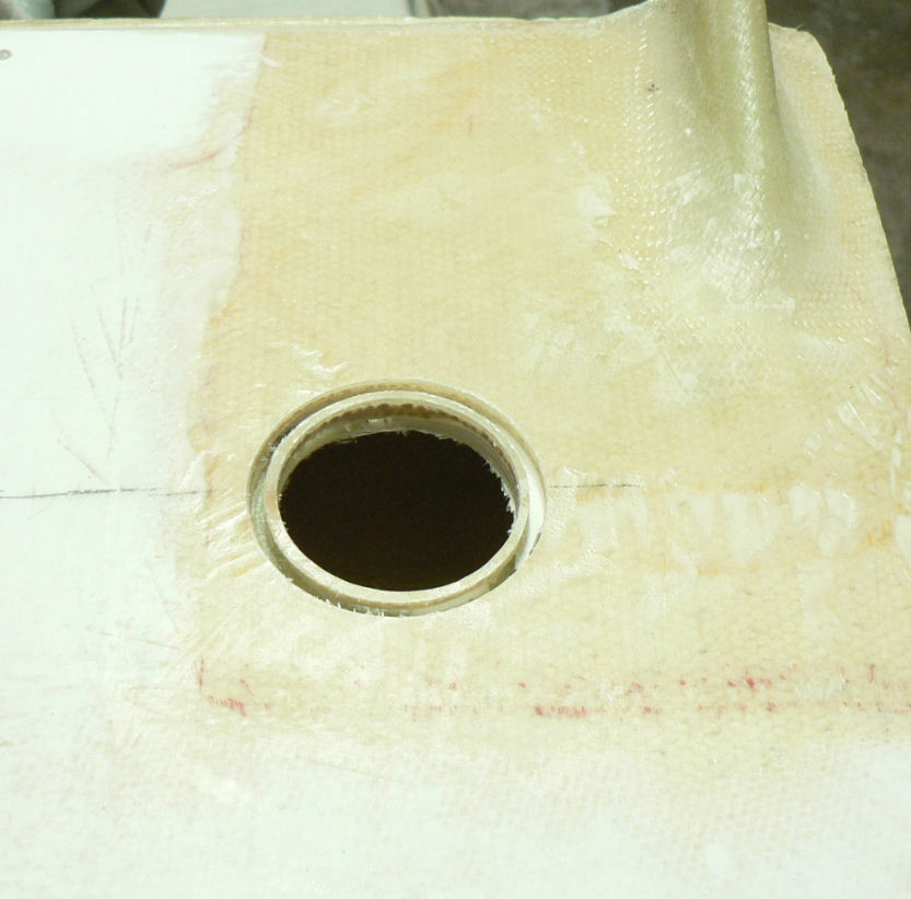
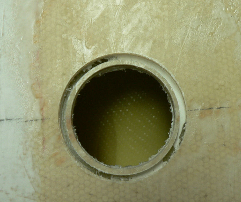
3-09-2007 Ordered bolts did not arrive yet, so cannot set LH flap yet - therefore no wing fairing progress yet. Marked out the RH wing quick drain position on the underside of the wing and the filler body position on the top side of the wing. Used a 50 mm hole-saw to cut a hole for the filler body in the top of the RH wing marked position. There was no gap between the wing surface and the fibreglass tank. Filed out the hole to take the 2" filler body and filed a slight chamfer around the top of the wing hole and removed the gelcoat around that area. Sandpapered the area of the filler body that is to be flocked to the tank & wing fuel filling hole. Cleaned it with acetone. Treated the matching part of the filler body and the fibreglass around the hole of the wing & tank with mixed epoxy. Added flock to the epoxy batch and mixed it until suitable for the job. Applied flock to the filler body and the hole surfaces ready for the filler body. Inserted the filler body in the wing hole with the top flush with the wing. Smoothed the top edges up by filling with flock till level. Made sure no flock remained on the inside of the filler body especially where the filler cap will sit. [ATTACH]3508.vB[/ATTACH] Had to leave two heaters running to keep the temp above 16 degrees C and it is barely doing that. So it will be a very slow cure - about 6 hours now and nowhere near right yet.
-
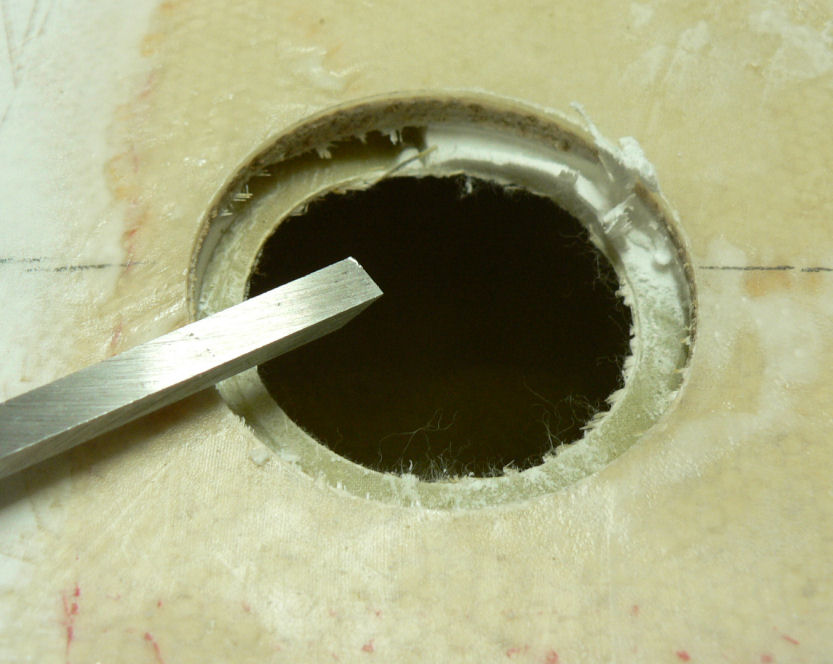
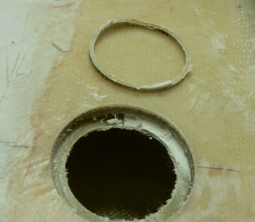
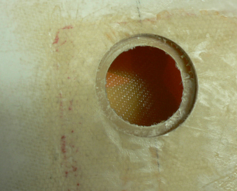
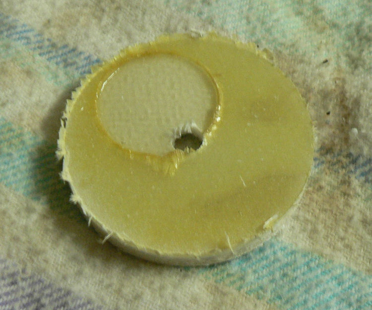
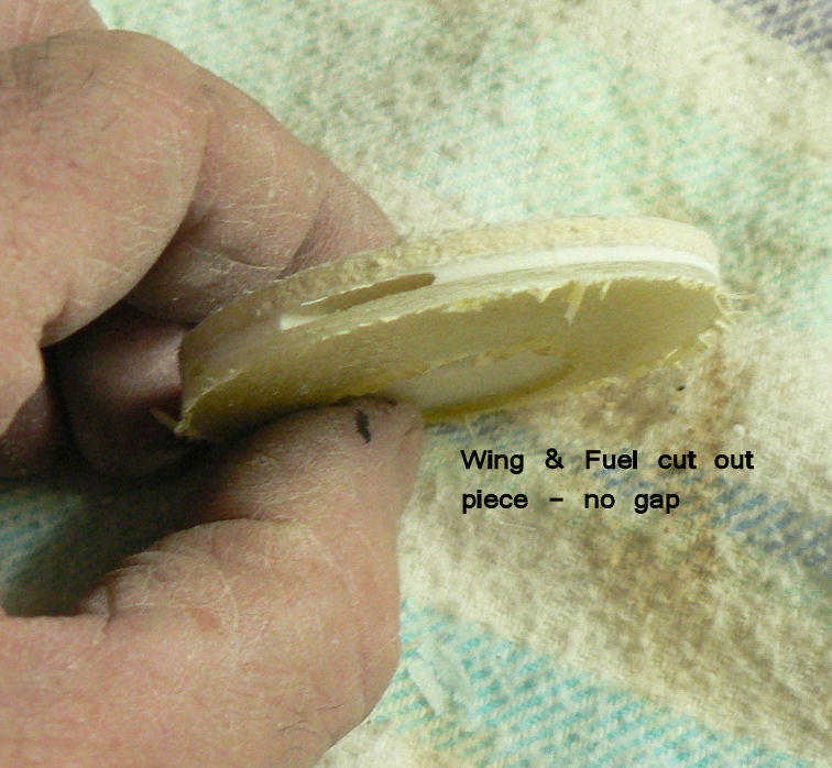
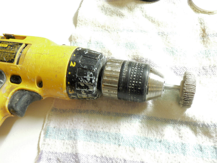
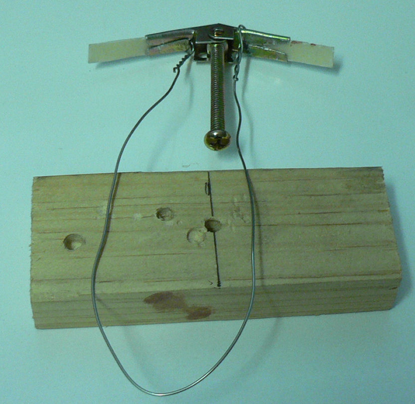
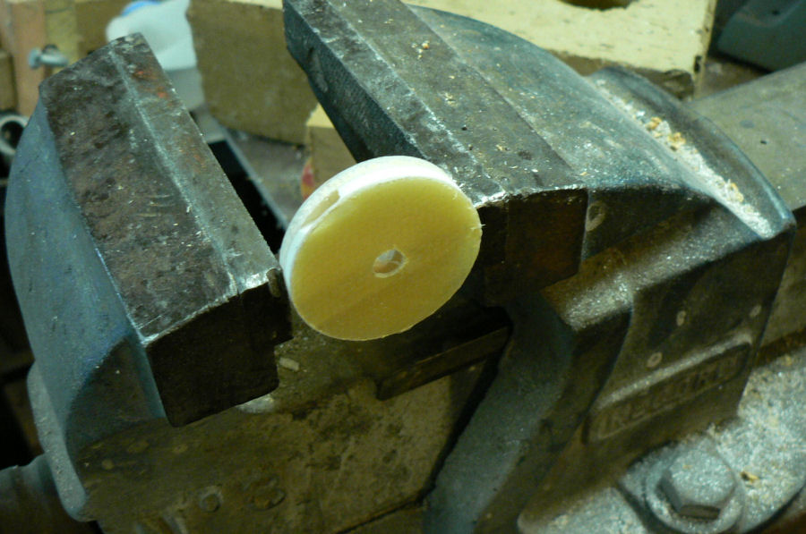
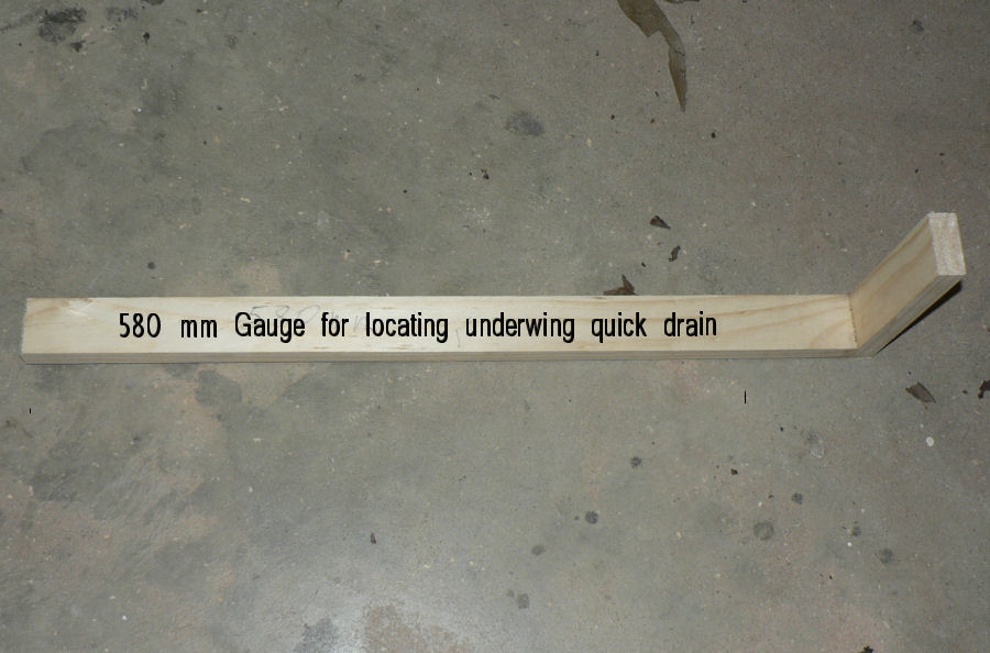
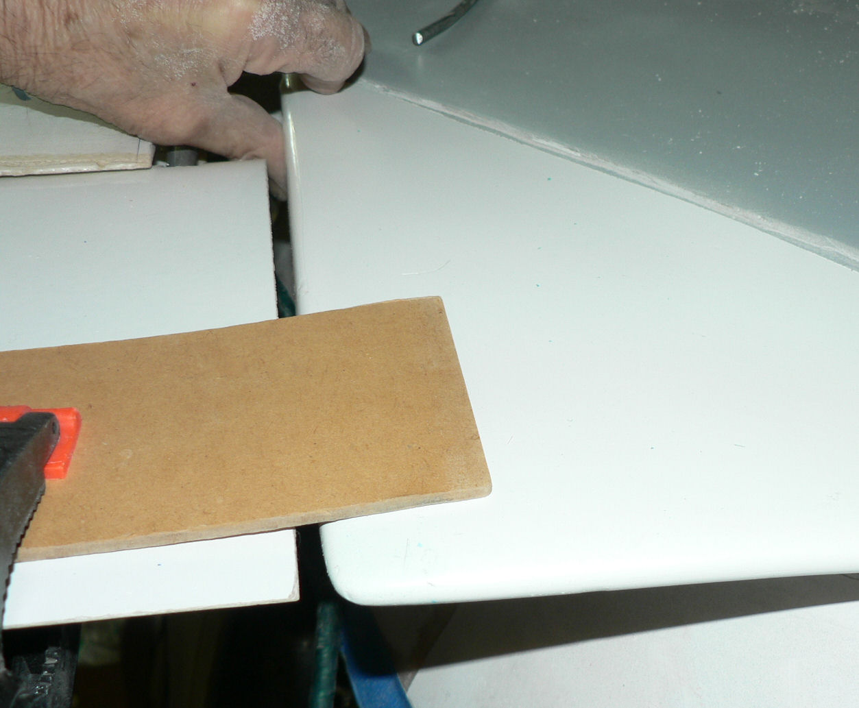
01-09-2007 Decided to do the measuring, holesawing and drilling for inserting the LH wing Fuel Drain. "Carefully" measured 580 mm from leading edge under left wing. [ATTACH]3455.vB[/ATTACH] Made up a wooden gauge to make a one person job of it. "Carefully" measured three times from underneath inner edge of wing to area near rear fuel take off in the wing about 58 mm. Marked out carefully (40+58) mm to intersect the 580 mm distance from the leading edge. Carefully used a 44 mm hole-saw to cut through the wing and intended to stop as the saw encountered the gap between the wing and the fuel tank - there was no gap! The tank was glued to the wing for about two thirds of the spot chosen to drill the hole! One advantage of this it will be easy to ensure there is no loose waste in the tank close to the drain. I can even get a couple of fingers in there.:confused: [ATTACH]3448.vB[/ATTACH][ATTACH]3449.vB[/ATTACH] 44 mm diameter holes through the wing and the LH fuel tank in the area close to the most inboard flap bracket support. [ATTACH]3450.vB[/ATTACH][ATTACH]3451.vB[/ATTACH][ATTACH]3452.vB[/ATTACH] Drilled a 3/8" hole through the combined piece before separating them. Gave the heat gun and pocket knife a workout again to separate the removed portion of the wing and the piece of the fuel tank. That only took about two minutes after the heat gun was hooked up to power and the pocket knife located. [ATTACH]3453.vB[/ATTACH] [ATTACH]3454.vB[/ATTACH] Enlarged the 3/8" hole in the wing portion to take the fitting for the quick drain. Temporarily plugged the hole in the underside of the wing & tank to keep out visitors.
-
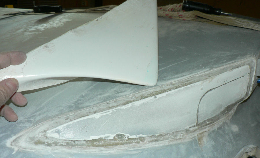
31-08-2007 Waiting on bolt supplies which I half expected today to set up the LH wing to flap fairing. See explanation in the previous post. I rang Doug Smith today at Jabiru to find the gap between the flap & fuselage fairing should be 3 to 5 mm. The fairing should also be set level with the flap in the neutral position. Mine started off before trimming at about 20 or 30 mm higher than the approximate neutral position of the flap and a gap of over 10 mm. I will check again when I get the flap properly connected to the control rod to establish the neutral flap position! As Doug said this may not be the final position of the flap after test flying as either flap might be adjusted up or down slightly to obtain level flight. LH fuse to flap fairing [ATTACH]3427.vB[/ATTACH] Removed RH fairing[ATTACH]3428.vB[/ATTACH] In the photo above the LH fairing is not epoxied in place only held by hand, the other hand is holding the camera! It only took a few minutes to remove the RH flap fairing using a wood chisel about 20 mm wide and the heat gun. While the epoxied flock used was still warm & soft it was fairly easy to remove any superfluous flock from the RH flap fairing.
-
Hi Geoff As you can imagine I am short one bolt long enough to connect the flap rod solidly to the flap - I thought that it might arrive today - but it did not arrive - maybe monday! In the photo thus far the flap is almost in the neutral position - the lever (not shown) certainly is in the flap photo! The LH fairing is is only held there by hand and will not be epoxied in until I can establish the initial neutral flap position. I was thinking it would be pretty difficult to get the fairing to line up with the trailing edge of the flap with a gap of 3 to 5 mm - I checked with Doug Smith at Jabiru. But I trimmed it with a pair of snips and I think the fit will be OK with a bit of extra filling as you will see in today's photo, again only held in place by hand. I removed the RH fuselage to flap fairing today ready to start again - it was about 20 or 30 mm above the level of the flap and the clearance was too large. So I am heeding your advice fully on the LH fairing. I thought that I had seen a reference to setting the flap neutral position by using the straight edge from the front of the underside of the wing to the trailing edge of the flap. There would be a gap of 4 mm at the trailing edge of the wing. But I cannot find it yet - I might have to start with your zero gap. Regards
-
A wheels up landing would be a sight provided you saw it from outside!:confused::confused: