Ross
-
Posts
729 -
Joined
-
Last visited
Content Type
Profiles
Forums
Gallery
Downloads
Blogs
Events
Store
Aircraft
Resources
Tutorials
Articles
Classifieds
Movies
Books
Community Map
Quizzes
Videos Directory
Everything posted by Ross
-
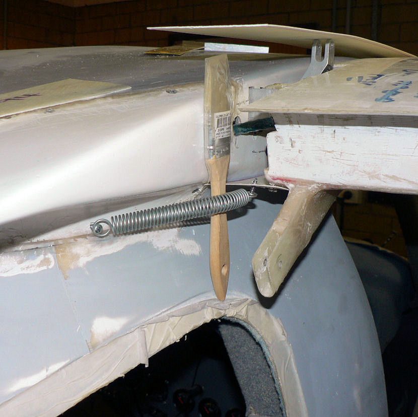
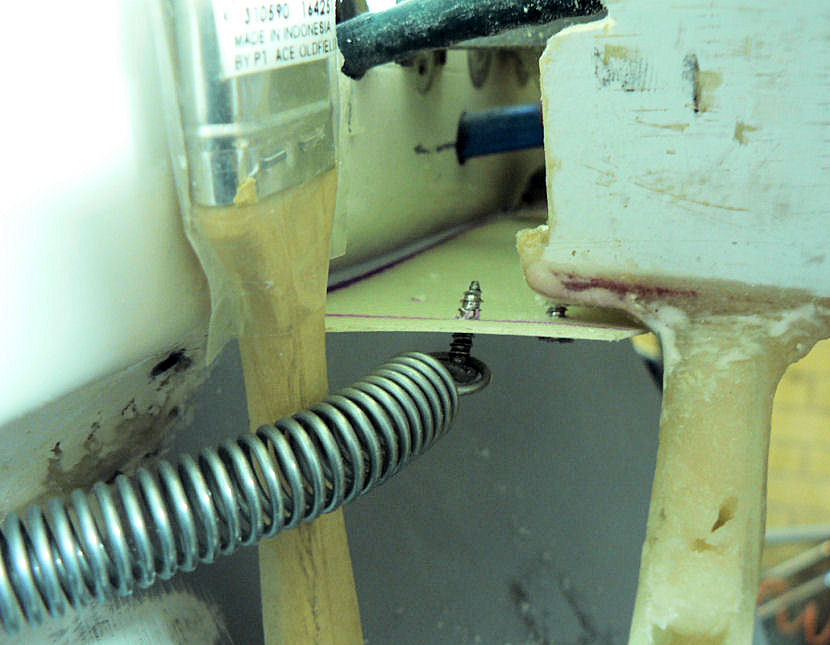
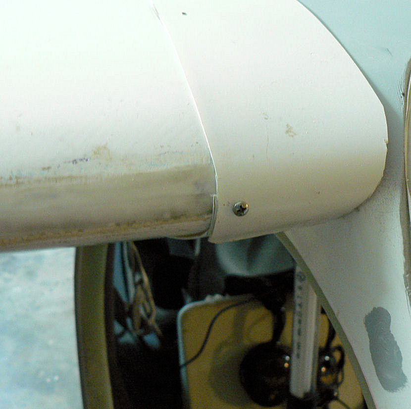
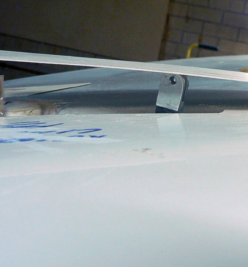
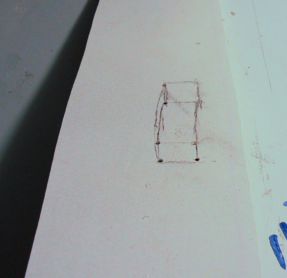
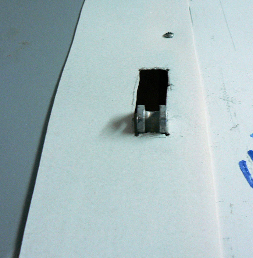
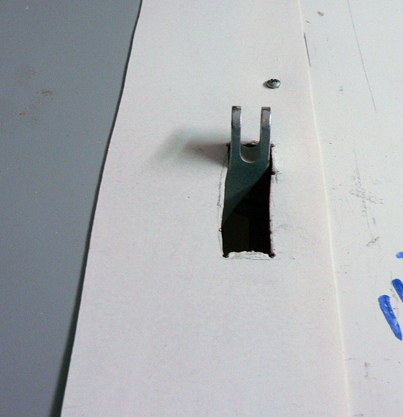
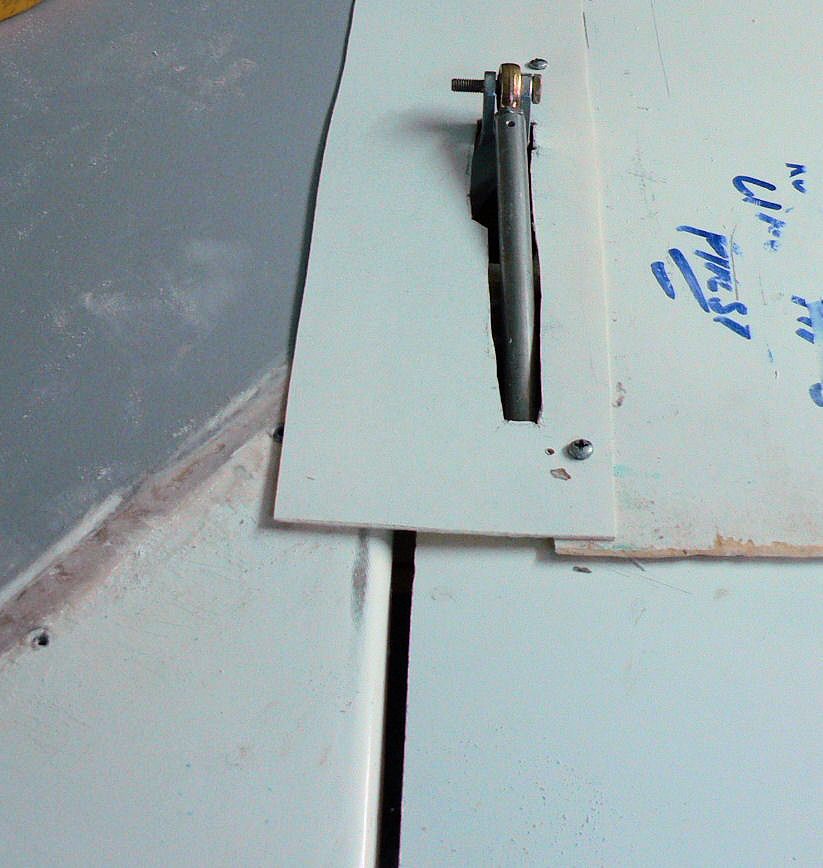
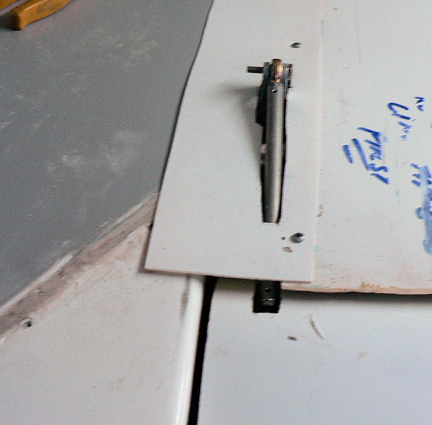
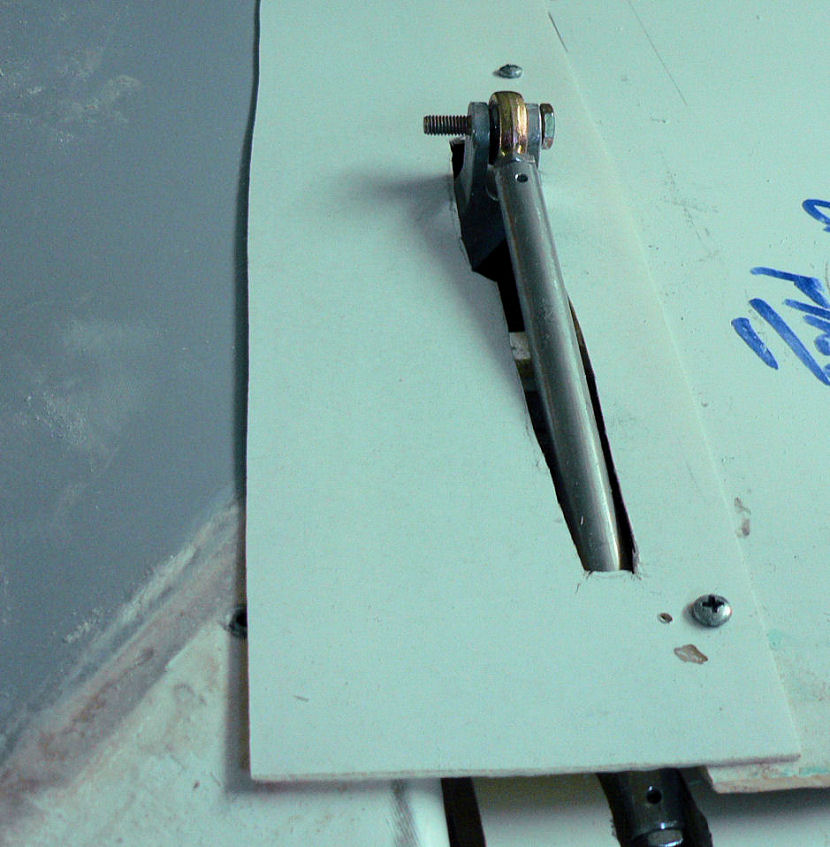
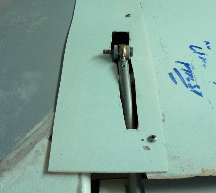
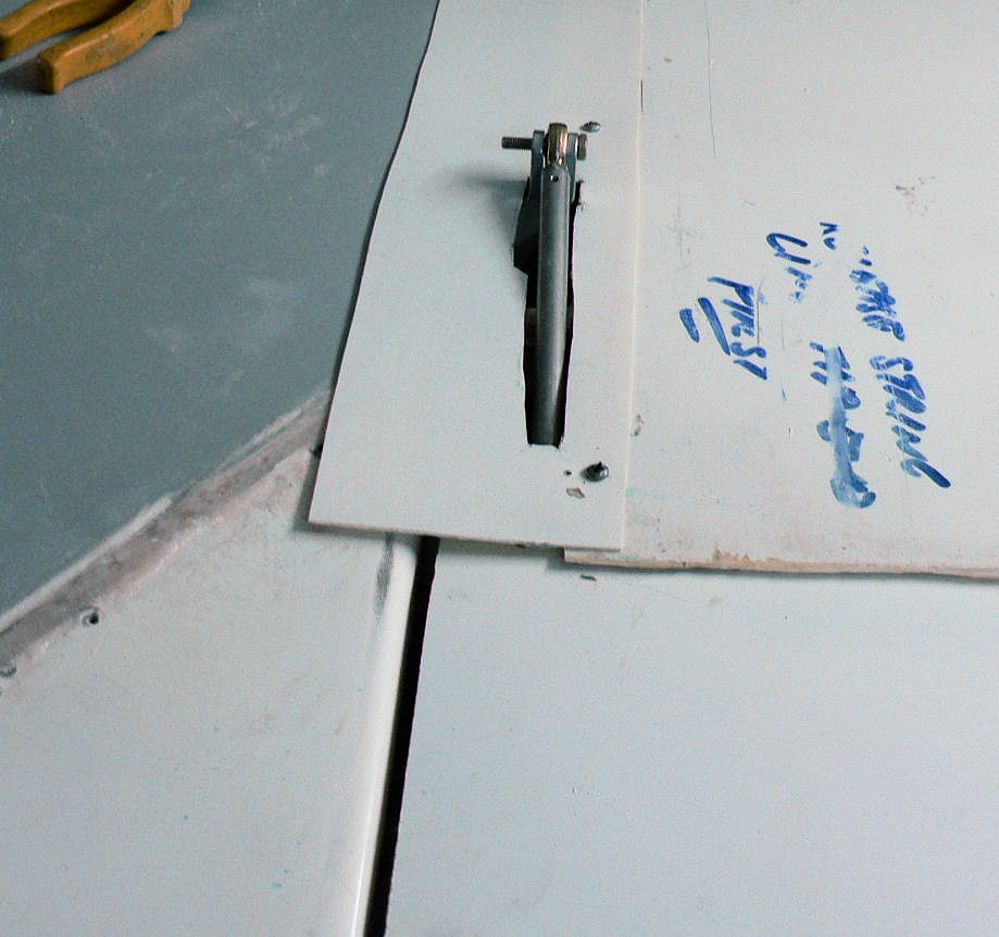
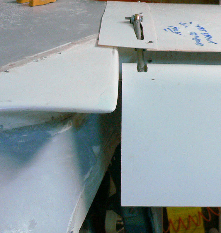
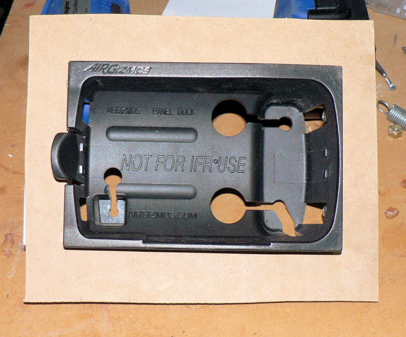
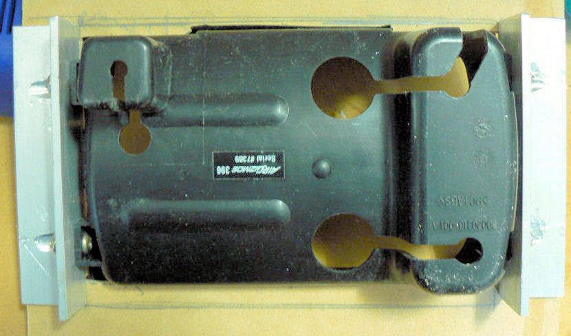
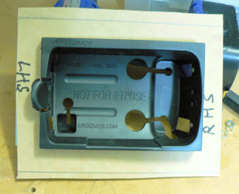
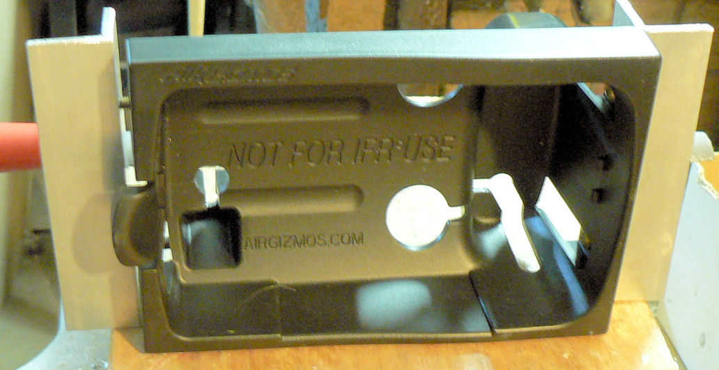
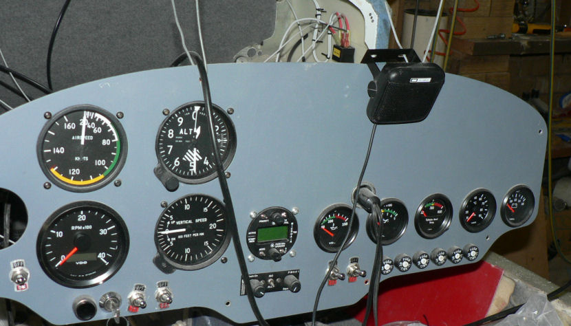
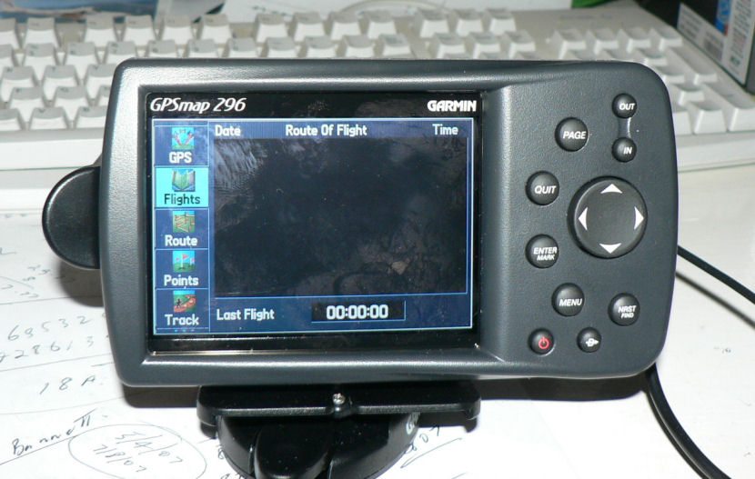
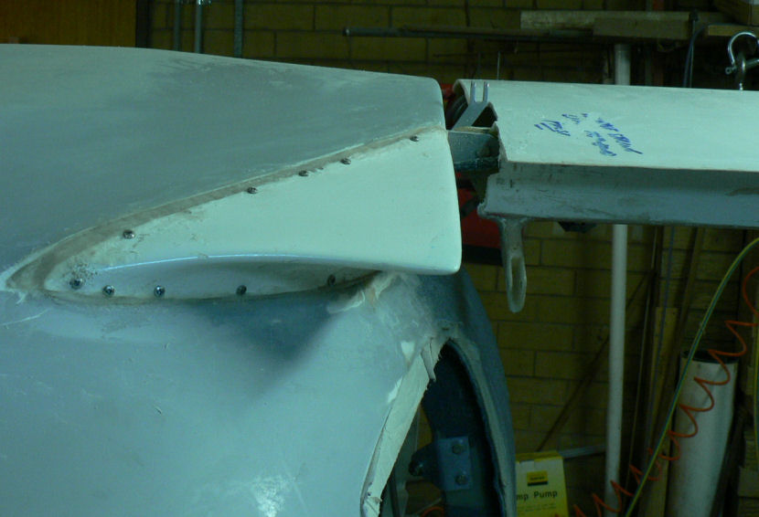
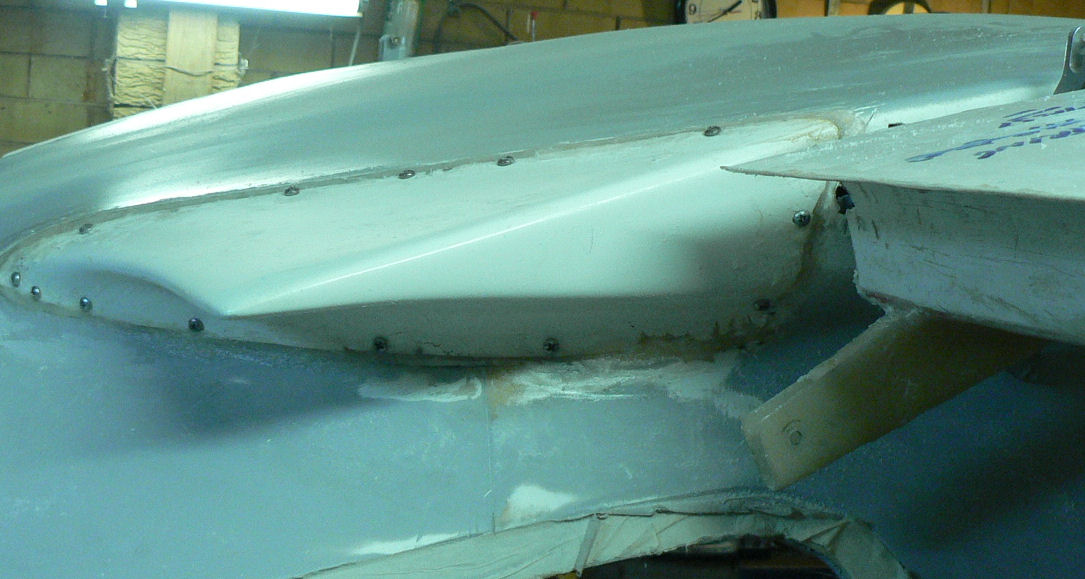
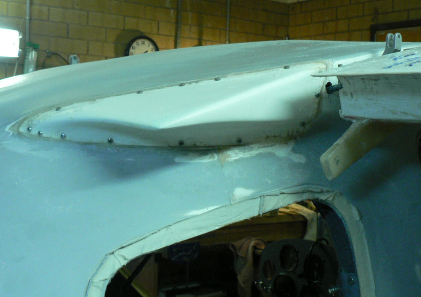
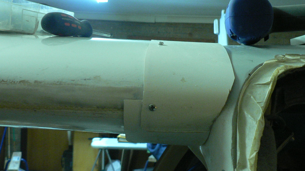
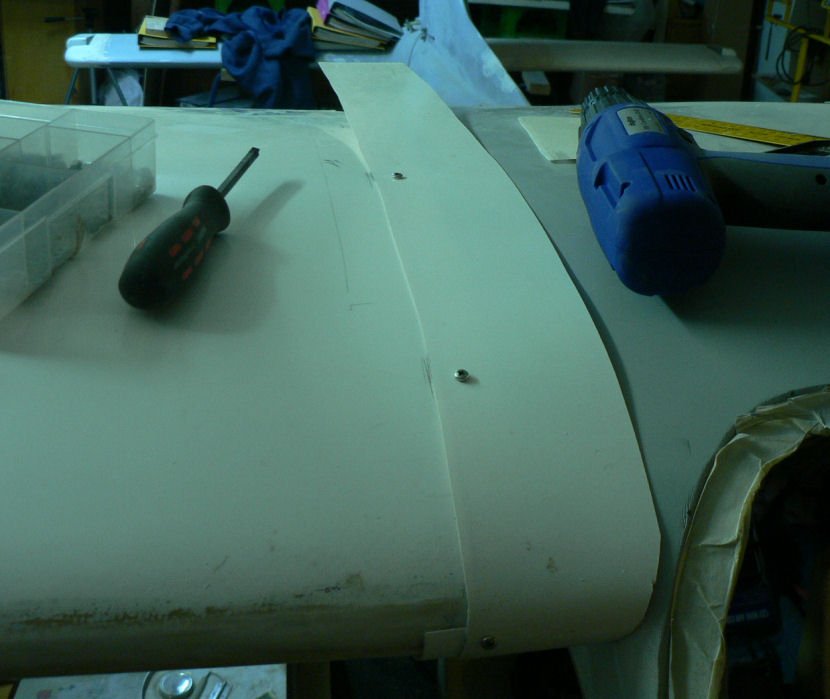
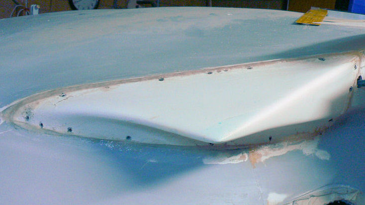
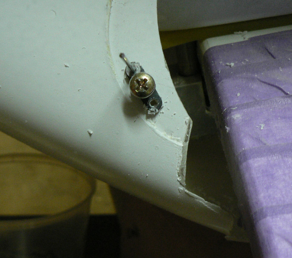
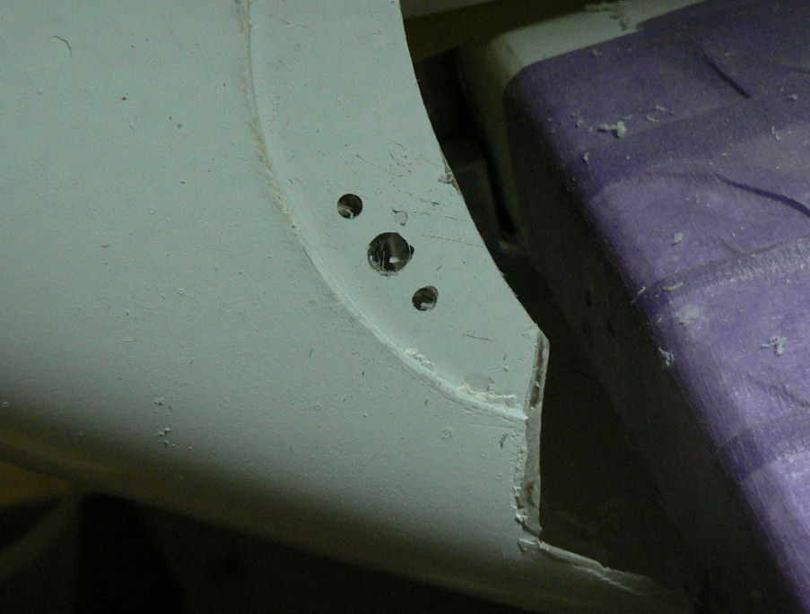
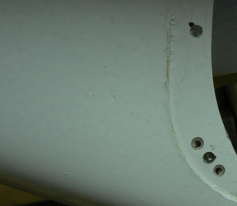
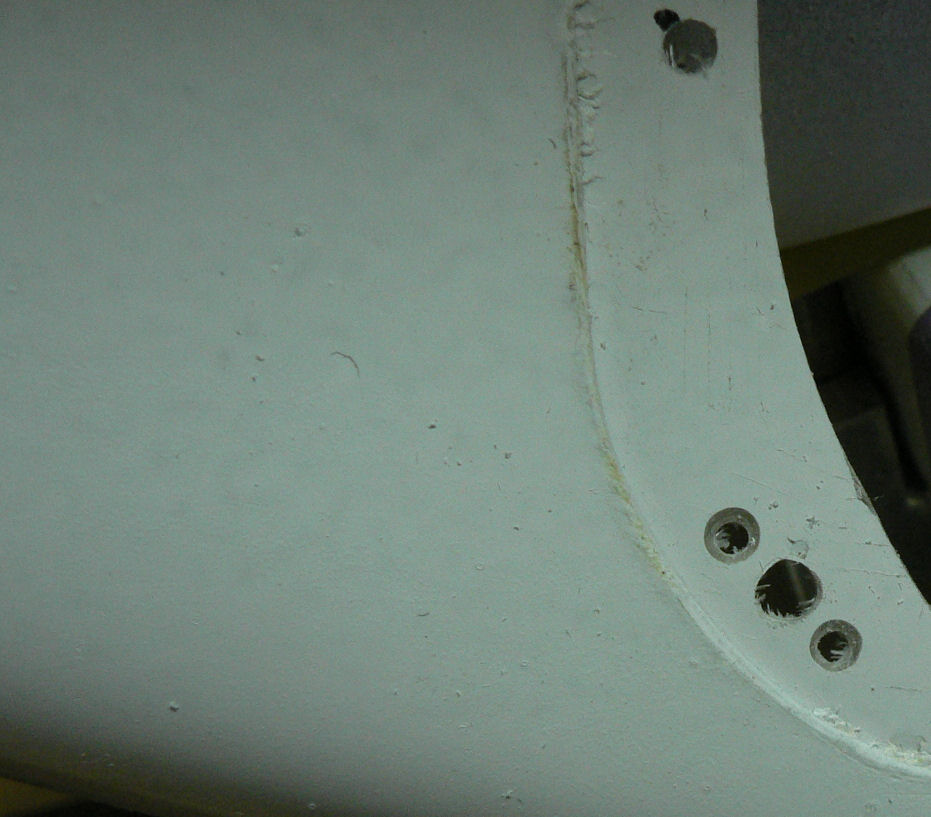
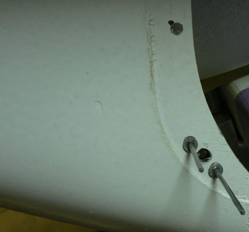
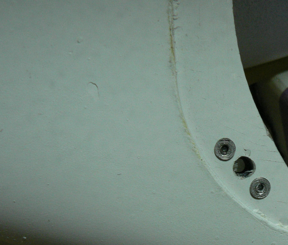
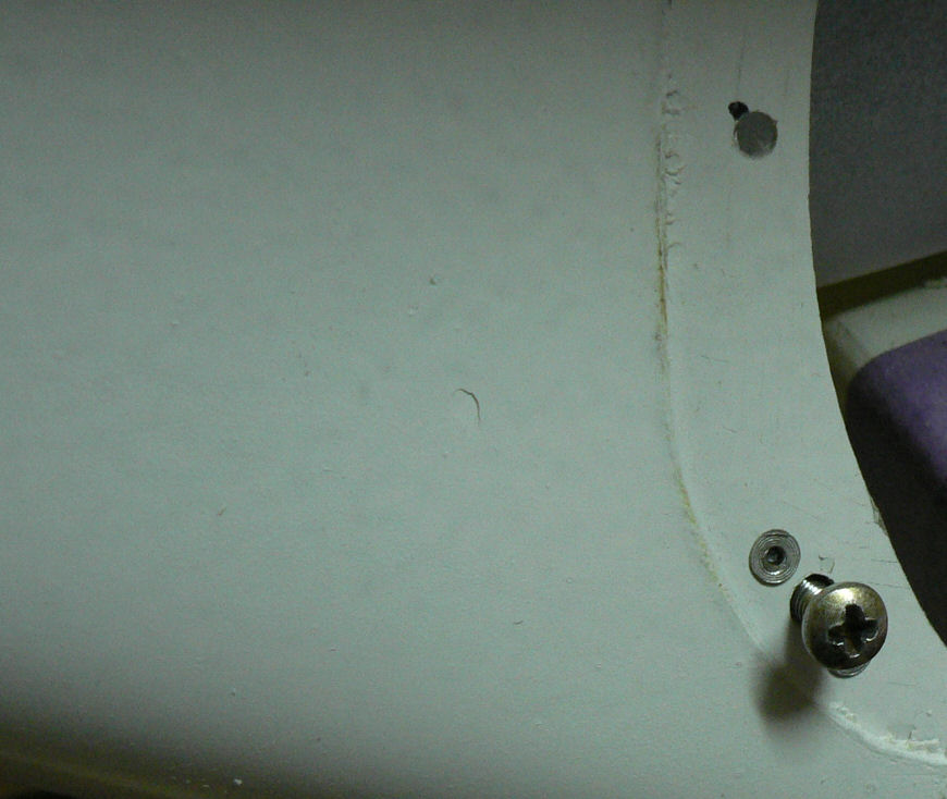
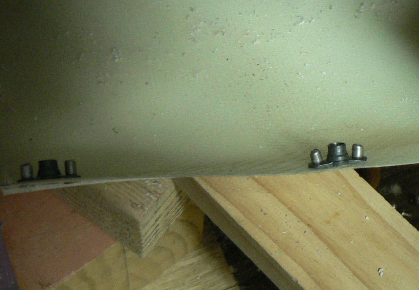
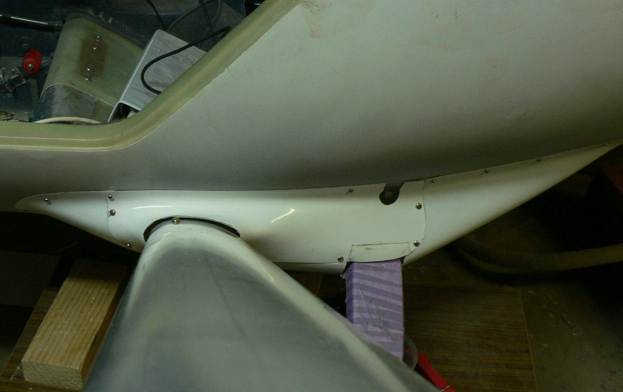
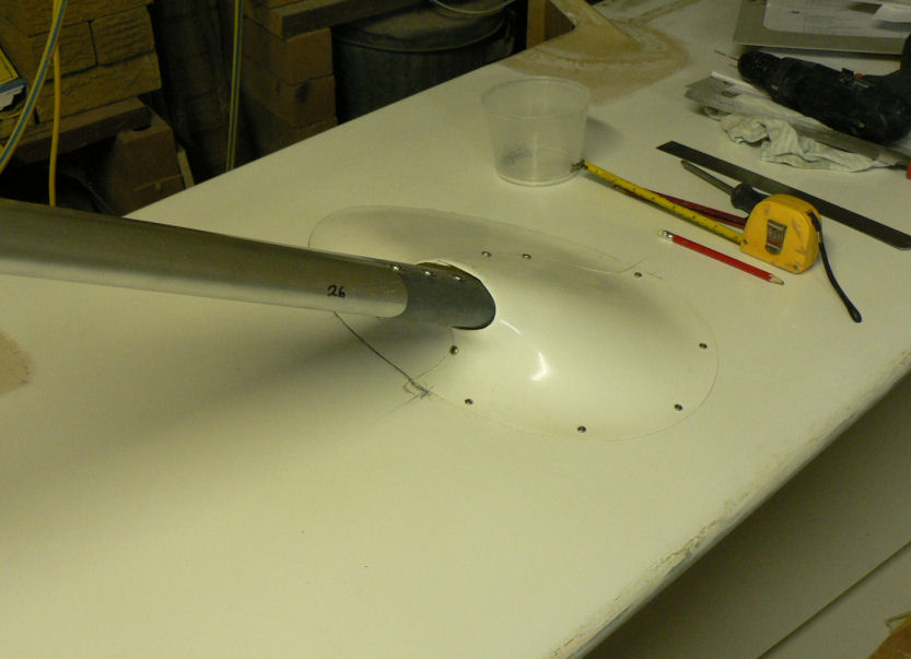
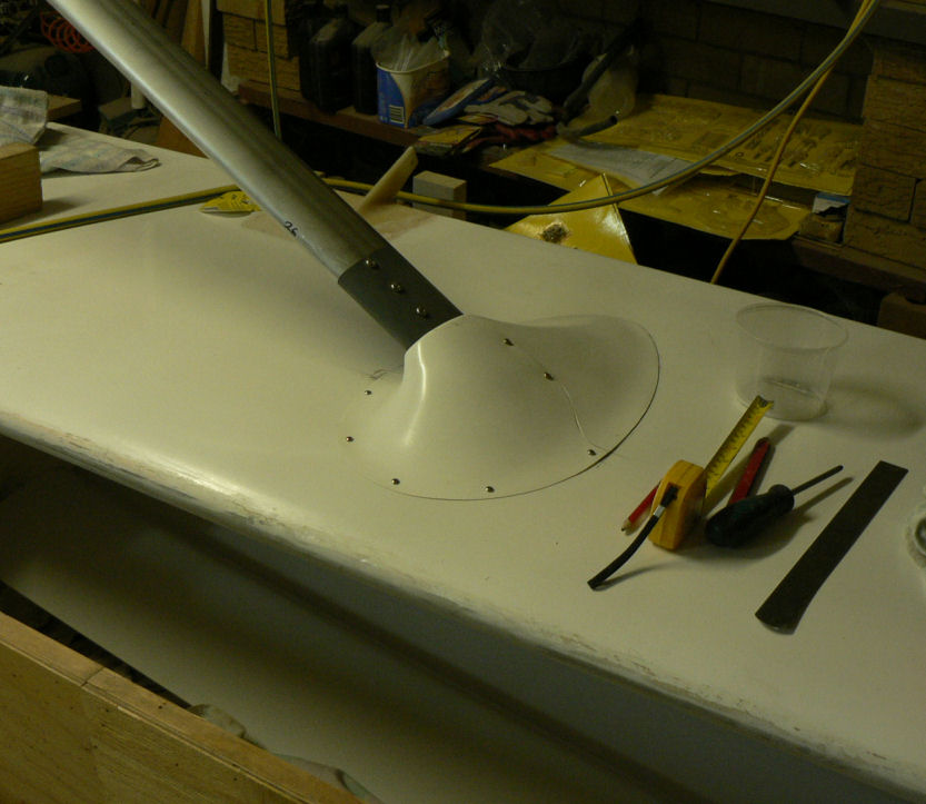
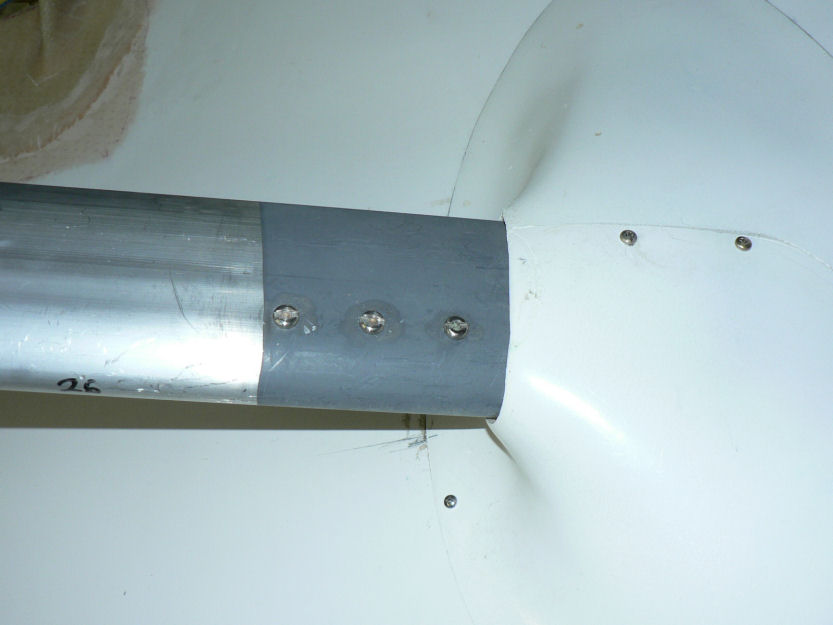
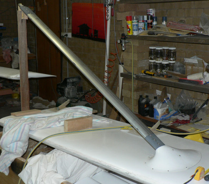
05-10-2007 Filed down the epoxy join of the RH eyebrow. Still need to fill the screw holes with the next batch of epoxy flock that is mixed. Continued with cover strip for RH wing root. Cut the hole for the flap lever from the cabin and cut the slot for the flap rod in the top half of the RH cover strip. Tensioned the bottom cover strip using a coiled spring and drilled more holes & inserted SS self tappers on the wing side. Trimmed the leading edge of the bottom cover strip. [ATTACH]3864.vB[/ATTACH][ATTACH]3865.vB[/ATTACH][ATTACH]3866.vB[/ATTACH][ATTACH]3867.vB[/ATTACH][ATTACH]3868.vB[/ATTACH] [ATTACH]3869.vB[/ATTACH][ATTACH]3870.vB[/ATTACH][ATTACH]3871.vB[/ATTACH][ATTACH]3872.vB[/ATTACH][ATTACH]3873.vB[/ATTACH] [ATTACH]3874.vB[/ATTACH][ATTACH]3875.vB[/ATTACH][ATTACH]3876.vB[/ATTACH][ATTACH]3877.vB[/ATTACH][ATTACH]3878.vB[/ATTACH] [ATTACH]3879.vB[/ATTACH][ATTACH]3880.vB[/ATTACH][ATTACH]3881.vB[/ATTACH] Partially blanked off the back of the wing in front of the flap to reduce air loss through the flap actuating slot. Like the later models needs a fairing over the top of the rod & lever to seal the gap. Made up a template for the GPS to help mark out a hole on the instrument panel. The template still needs to be squared up on the outside. Had to slot the holes in the caddy to get some depth adjustment. Its mounting system could do with a redesign for ease of access and installation unless the brackets were put on the panel side in view of the pilot which would be a bit questionable in the aviation fashion stakes. No matter what you do with it you need access to the back of the panel even if you fit retained nuts to all screws. [ATTACH]3882.vB[/ATTACH][ATTACH]3883.vB[/ATTACH][ATTACH]3884.vB[/ATTACH][ATTACH]3885.vB[/ATTACH] Another shot of the GPS in the office - this time with the antenna stuck on the bottom pane of the office window - the section with no gauze on the outside. I thought it was plastic.

-
Hi Ranger I remember in my early days that one of the problems with some of the aircraft that I and other low time pilots were learning to fly was that they seemed to suffer from some form of extreme vibrations or shaking. We all eventually learnt that it could be fixed by simply unclenching and removing the tightly clenched fist from around the control stick. Enjoy your flying more and more as it becomes familiar and automatic. Regards
-
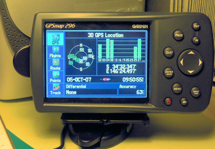
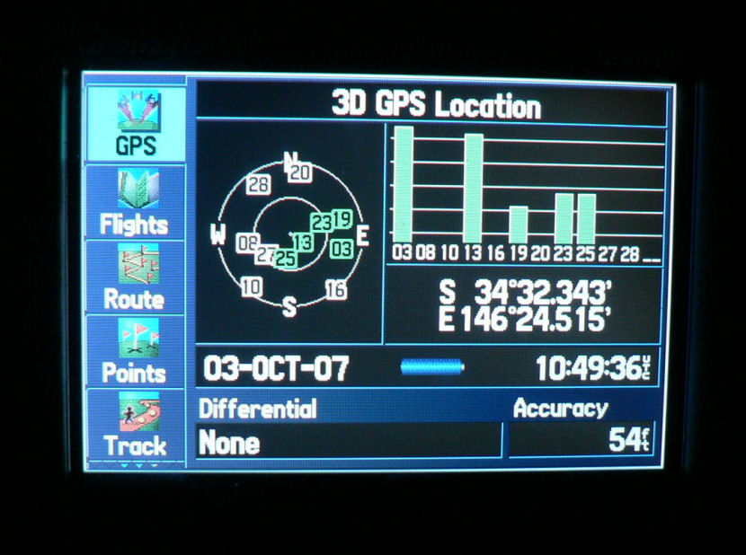
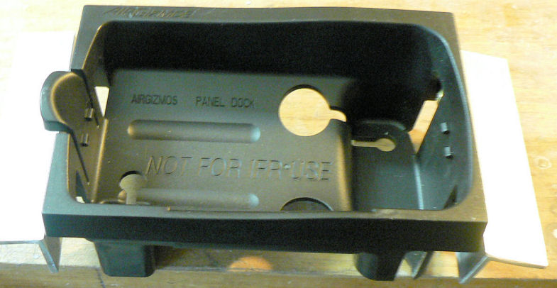
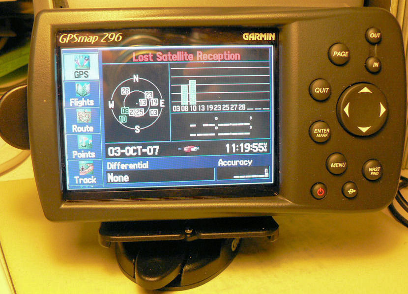
3-10-2007 I lashed out and bought another item that is going to cause me to take a few steps back as I will have to remove most of the instruments from the panel to cut a new hole for it. The caddy is a bit awkward as you need to make up brackets to attach it to the panel and the holes in the caddy are placed so that the nuts on the aluminium equal angles will probably not allow use of a ring spanner. There is limited space on the panel and I will have to shift the power supply. [ATTACH]3852.vB[/ATTACH][ATTACH]3848.vB[/ATTACH][ATTACH]3849.vB[/ATTACH] Note the two GPS screens. The one with many birds was done almost outside in our gauzed in area using battery power and the short antenna on the 296 on the Eastern side of the house. The other GPS screen was taken a bit later as you can see by the displayed UTC time and date on my office desk with mains power and the external antenna on a lead stuck to the office window ( with a vertical aluminium blind on my side) on the western side of the house. Maybe the blind is affecting it. But there are also some trees close to it but screening about 20 degrees of the available sky. The second GPS screen shot also has the 296 sitting in one of its quick release caddies that come as standard. [ATTACH]3850.vB[/ATTACH][ATTACH]3851.vB[/ATTACH][ATTACH]3853.vB[/ATTACH] I had to return the 12/24 volt power chord. There was no way it would plug into the external power supply socket on the 296 whereas I had no trouble with the chord supplied for the transformer mains powered one. The really good part of these units is that they have a built in charger for the custom made on-board battery pack so that it automatically gets recharged if necessary and then shuts down while the external power is available. So normally you do not have to worry about the battery as long as your system is hooked up to the A/c power supply 12 or 24 volts DC. The 296 battery should automatically remain fully charged until the a/c electrical system fails. Interesting. The external antenna with suction cups just fell off the glass on the window so I sat it on the paper shredder which is further into the room by about 300 mm and on the wrong side of the Aluminium louvres. Three birds immediately appeared in the screen but the signal gets weaker if I put the antenna closer to the window! The walls are double brick.
-
Another two cents worth and probably worth less than that! The heavier an aircraft and providing it has some altitude it has more potential energy. If it is not moving and high enough the potential energy can be converted to kinetic or useful airspeed energy if high enough and also to overcome energy wasting drag. Usually, once it runs out of height it has run out of spare energy if the motor is not going and the airspeed is on the point of stall - don't turn back.. Drag is usually proportional to the square of the speed for turbulent flow wings. Increase the speed by 10% results in extra drag of 21%. But if the wing and the rest of the airframe has laminar flow characteristics the drag will be directly proportional to the speed not the square of the speed - hence the incredible glide angles of top performance gliders or sailplanes like 4 or more times better than a Jabiru.. In the same airframe the more mass up to a point the faster an a/c can glide but it needs to get rid of excess mass before the stall (sorry landing) to reduce the landing speed - chuck out the water or the pilot at the last moment! Really high flyers will know that the force of gravity decreases as the square of the distance from the craft to the centre of mass of the earth or the moon or the sun or the stars etc. Regards
-
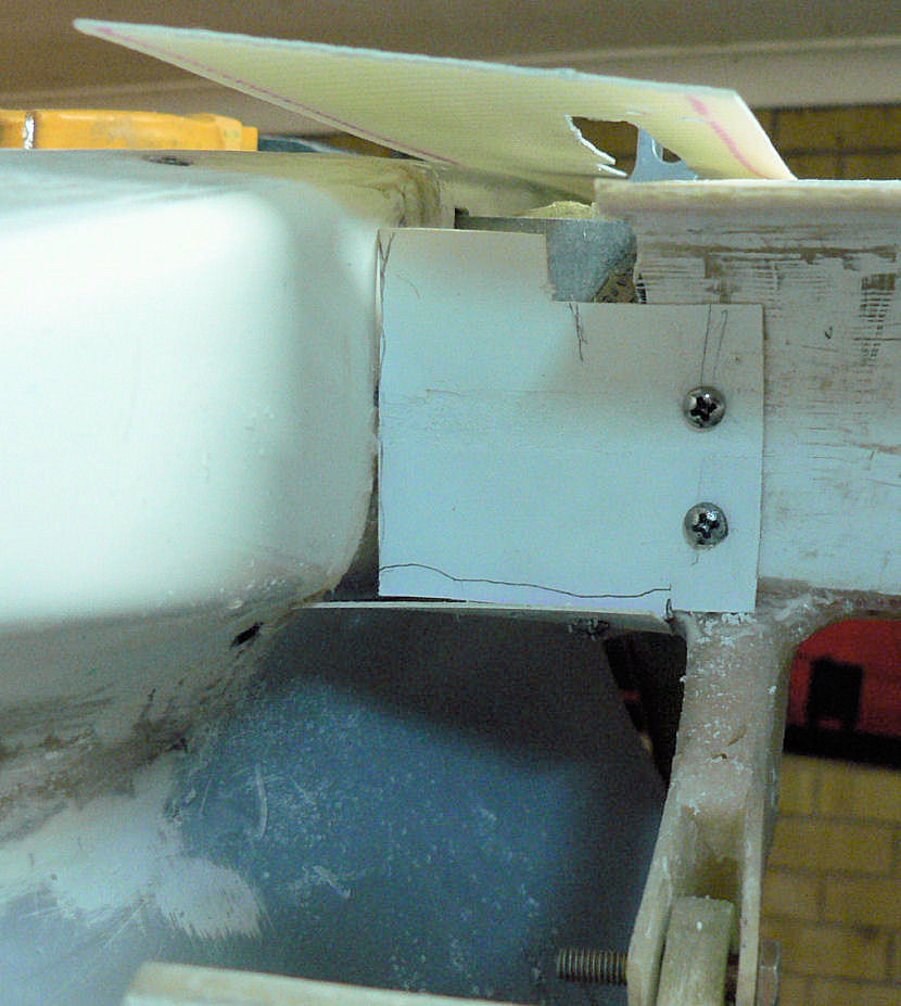
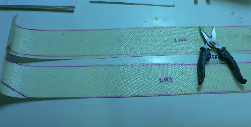
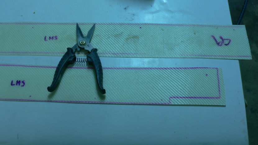
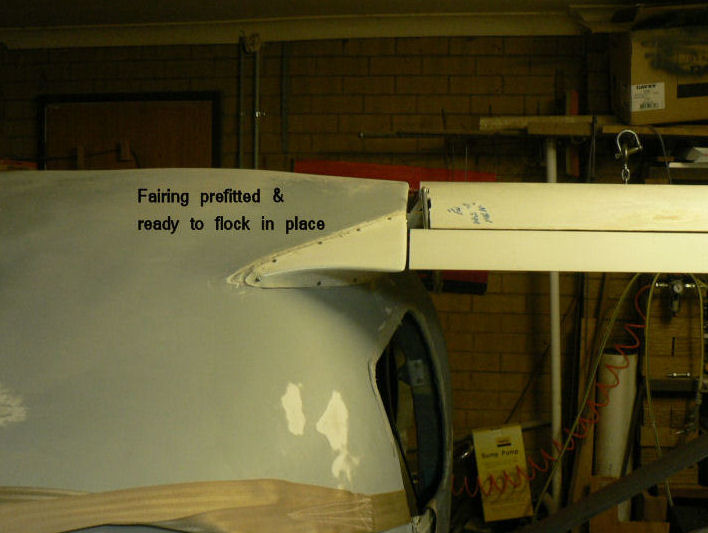
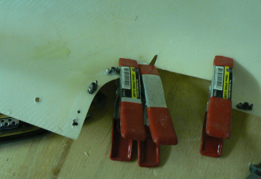
1-10-2007 Made up flock to attach the RH fairing to fuselage between fuselage & RH flaps. Applied epoxy to both mating surfaces and then applied flock to both and screwed the fairing back on while the flap was still attached. Good day for glass work as the temp in the garage kept rising from almost 20 degrees at 13:00 hrs to about 24.4 at 18:00 hrs. It is still 22 degrees at 21:00 hrs and the flocck is virtually cured. I will go and remove the screws as soon as I finish this post. [ATTACH]3825.vB[/ATTACH][ATTACH]3826.vB[/ATTACH][ATTACH]3827.vB[/ATTACH] After getting all the screws in for the fairing, started work on the cover strips for the RH wing root both top & bottom. The strips come marked for cutting & drilling. Having been caught before, I cut out the RH cover strip set splitting the material and leaving the waste material on the cover strip to be removed when I am sure I do not need it. I got the leading edge lined up reasonably and a few more screws in before I stopped work on it for the evening. So far it is just cut to fit, drilled some holes and inserted the self tapping screws mostly into the skin of the wing. I made sure not to penetrate the fuel tanks while trying to keep the cover strips tight! [ATTACH]3828.vB[/ATTACH][ATTACH]3829.vB[/ATTACH][ATTACH]3830.vB[/ATTACH][ATTACH]3831.vB[/ATTACH] Screws removed after saving the pic under a different name and cropping it slightly more to get it to load. [ATTACH]3832.vB[/ATTACH] Screws have now been removed & took a pic but I gave up trying to insert it. See note above. Took all the photos w/o flash under inadequate flourescent light (to eliminate the flares from the flash) and only remembered to use the "one step photo fix" in Paint Shop Pro on the last photo - apologies. But see the difference!
-
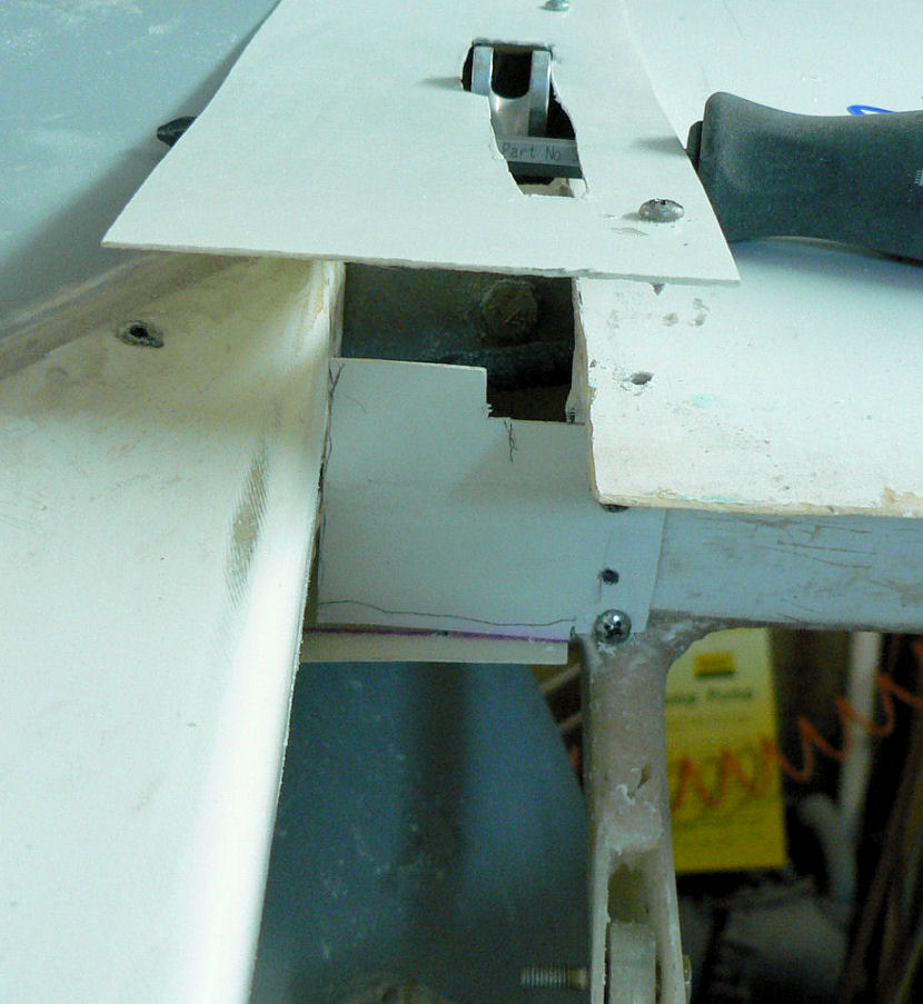
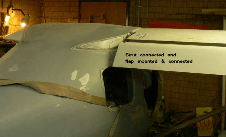
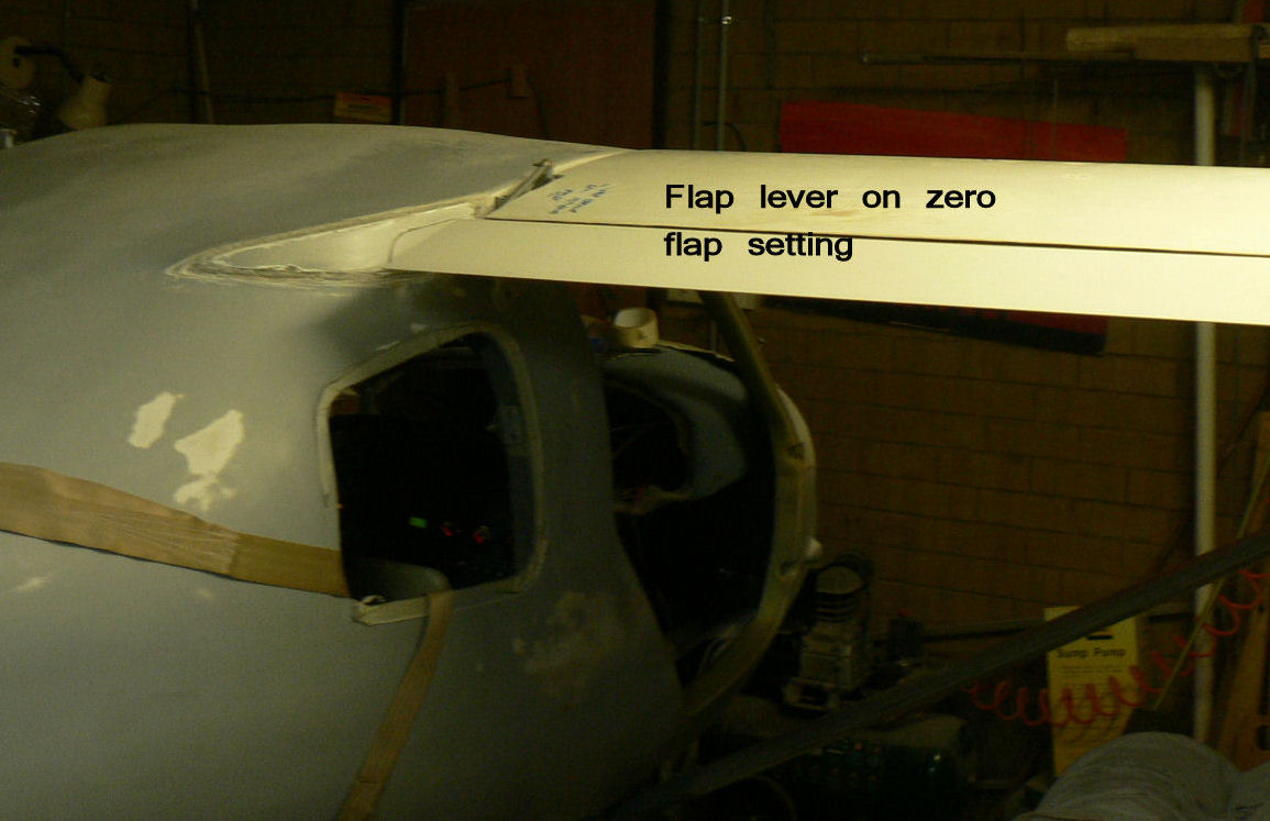
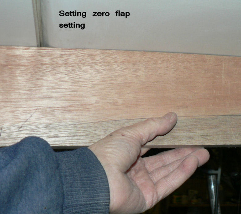
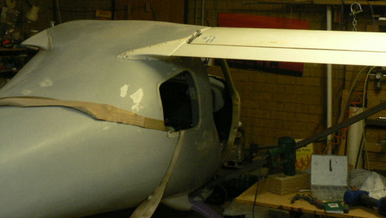
29-09-2007 Had a bad day not very productive. Hooked the RH wing up to the inboard mounting points. Had some trouble inserting the AN3 bolts but eventually got it lined up with some heating again of the SS bushes. Fitted the RH strut to wing & fuselage. Fitted the RH flap & checked the flap setting with flap lever fully retracted. Adjusted the flap rod length to give the correct flap position. Prefitted the fuselage to flap fairing so that the trailing edge is aligned with the neautral flap position. Inserted self tappers to locate the fairing position for attaching with flock. Monday will do. [ATTACH]3803.vB[/ATTACH][ATTACH]3804.vB[/ATTACH][ATTACH]3805.vB[/ATTACH][ATTACH]3806.vB[/ATTACH][ATTACH]3807.vB[/ATTACH]
-
28-09-2007 Brentc I wouldn't hold my breath waiting for it. I have heard it before as well some years ago. Today went to Griffith & got some more RAM for our computer. I want to bring it up to 2 GByte but Dick Smith is a bit expensive for 1 GB DDR ram. So did an interm job & got an extra 512 MByte to make it 1 GByte. It only has two slots and can take a max of 2 GB of DDR ram. Rearranged the AC to remount the right wing for attaching the fuselage to flap fairing. [ATTACH]3798.vB[/ATTACH][ATTACH]3799.vB[/ATTACH][ATTACH]3800.vB[/ATTACH][ATTACH]3801.vB[/ATTACH] When we got back from Griffith at about 13:00 hrs what looked like a Jabiru 230 was towing a long sign around over the centre of Leeton for quite some time and then repeated the act later in the afternoon. It was advertising some hotel in Canberra I think. I tried to get some photos but the scudding small clouds kept fooling my camera's auto focus and I just ended up with a number of white photos. During the later session there was a very strong almost westerly wind blowing and the Jab seemed to be having a very hard time against the head wind and dragging the sign. It hardly seemed to be moving at one stage but it sounded like a full throttle effort from the 3300 motor as it flew on both sides of our house at Leeton.
-
You obviously need to patent it before someone takes it away!
-
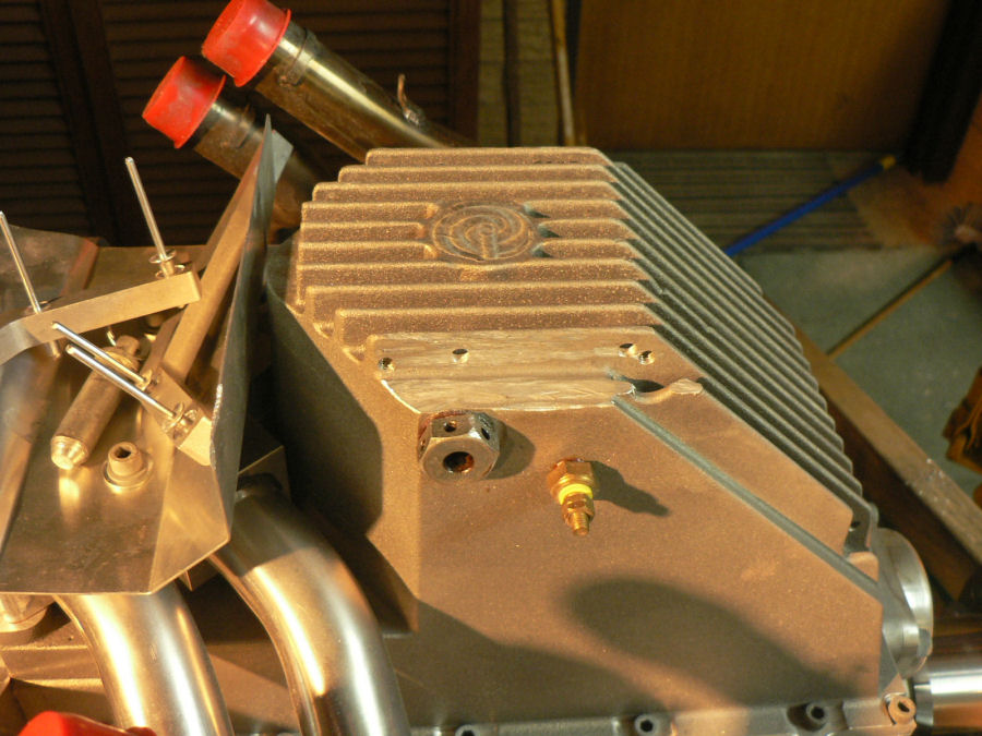
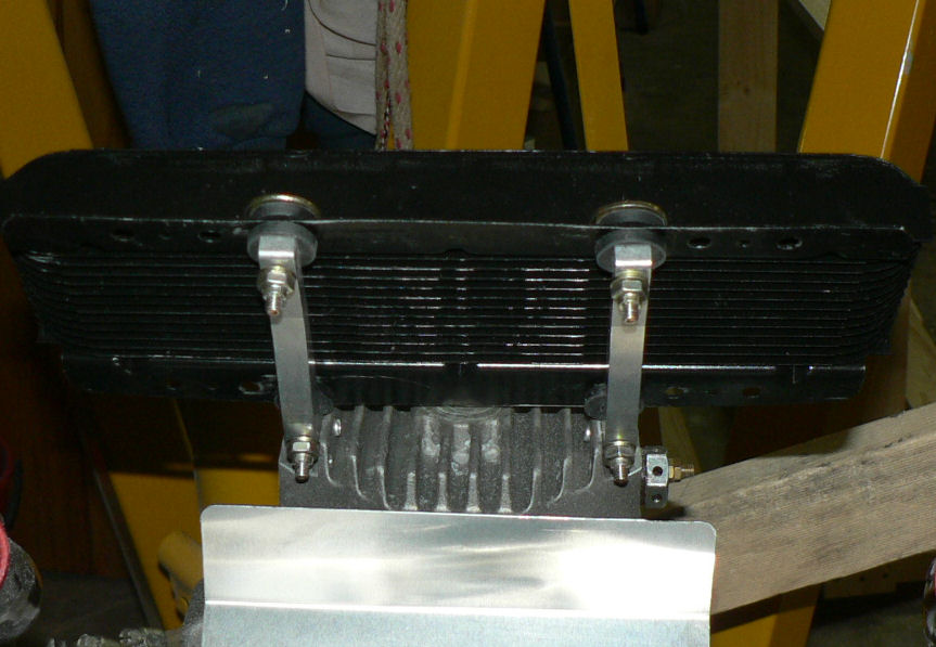
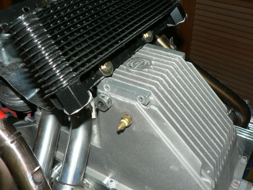
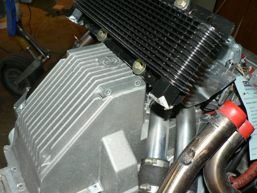
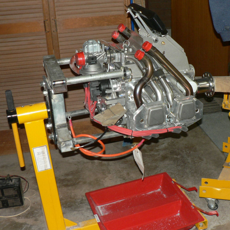
27-09-2007 Brian thanks for that. I eventually got the new chapter 77 of the construction manual from a Kody Barrett in the spares department at Jabiru. Kody said they have actually appointed someone to rewrite all the manuals. Removed the first fin on each side of the bottom of the sump with a right angle grinder. Drilled the brackets for fitting rivets and drilled matching holes in the second fins on each side of the sump. Filed a radius on the inside of the brackets facing the second cooling fin on the sump. Countersunk the rivet holes otherwise the rivets will be too short and much neater. Mounted the brackets & marked the cooler for drilling and drilled it then the brackets. Drilled out the brackets to 1/2" to take the rubber grommets. Cut bushes from 5/16" Bundy tube and inserted them into the rubber bushes. Mounted the cooler on the brackets and attached using 2 AN3-14 bolts and 2 AN3-12 bolts with the penny washers, a 3/16" washer and fireproof nuts. In these views the engine is upside down - much easier to work on! [ATTACH]3790.vB[/ATTACH][ATTACH]3791.vB[/ATTACH][ATTACH]3792.vB[/ATTACH] [ATTACH]3793.vB[/ATTACH][ATTACH]3794.vB[/ATTACH][ATTACH]3795.vB[/ATTACH][ATTACH]3796.vB[/ATTACH] Allthough the sump plug was wired up with safety wire it was only finger tight.
-
One of our local farmers has a Foxbat from new that I think has done a couple of hundred hours so far. I have not heard any adverse comment on it so far. Regards
-
Many years ago we had an instructor, Bert Johnson I think, from the Southern Cross Gliding Club in Sydney visit our Leeton Club with a group of glider pilots some of whom were trying to get their cross country endorsements. One of his tests was to take a new pilot up and fly to Leeton about 5 or 6 km and then fly back over the strip and ask the student pilot where was the airstrip. A surprising number according to some of them had no idea where the field was.;) I will not add any further comment except that I was not one of HIS students! Well a feature of this fellow was that he had an artificial leg and pointed out that sometimes it was an advantage. He related how one day visiting somebody their dog raced out and bit his artificial leg or tin leg as he called it. A very surprised dog was the result. :confused: The dog did not continue the attack. Regards
-
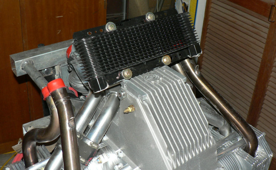
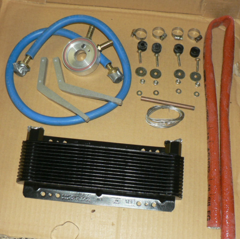
25-09-2007 The material supplied for the oil cooler J160 kit#14 does not agree with my construction manual so I am waiting on a reply to an email sent tonight to Jabiru. [ATTACH]3738.vB[/ATTACH] Any suggestions or pics from other J160 Jab owners welcome. Regards
-
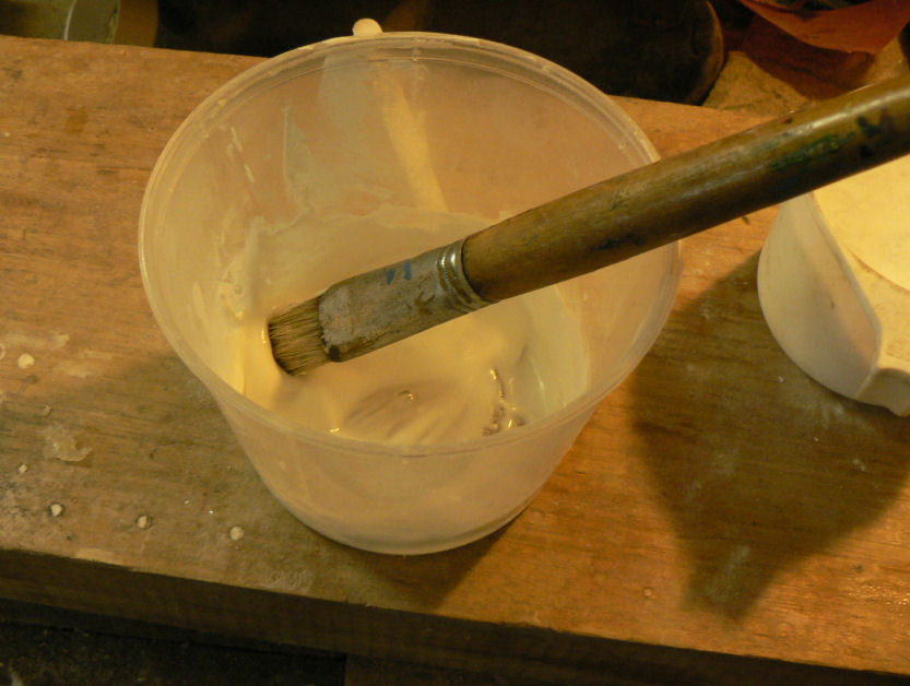
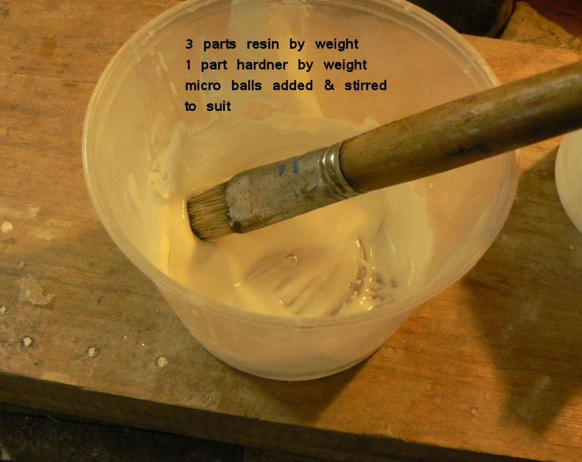
25-09-2007 I was surprised to find that it only took me about ten minutes to smooth up the microball fill to the stage where a combination bog undercoat would cover any remaining bumps. I used an rectangular shaped orbital sander, a rotating sanding wheel mounted in an 18V drill and a hand held piece of sandpaper. [ATTACH]3735.vB[/ATTACH] However the next bit - cutting the hole again and fitting the strut took me a couple of hours. I could probably hook up the bottom strut now with my eyes shut. Used a jig saw with a fine tooth blade, a half round file, a round file and a permanent marker. Acetone removes the permanent marks. [ATTACH]3736.vB[/ATTACH][ATTACH]3737.vB[/ATTACH] There is still the fuselage to flap fairing to fit on the RH side which will get done when the AC is turned around in a more favourable position.
-
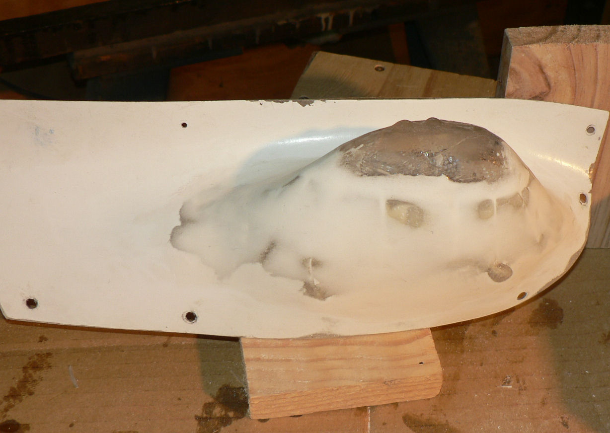
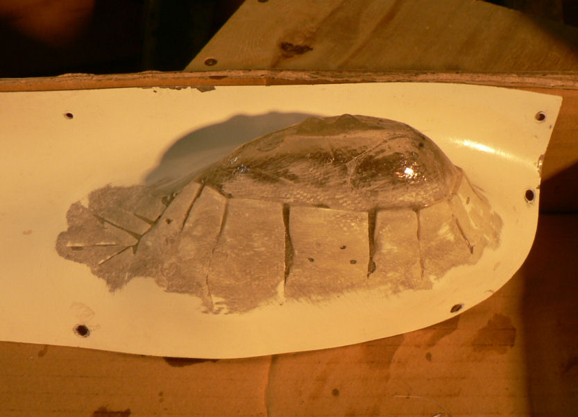
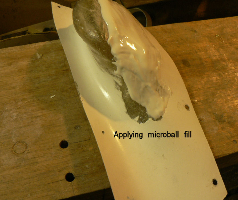
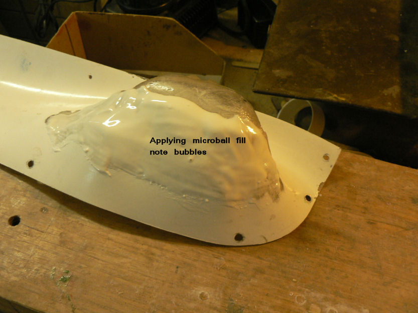
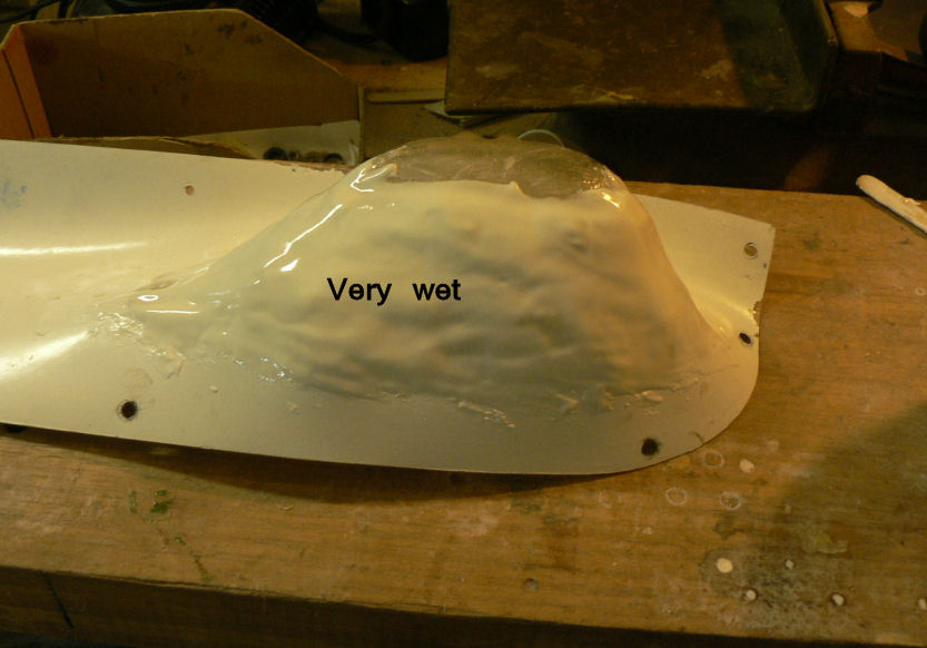
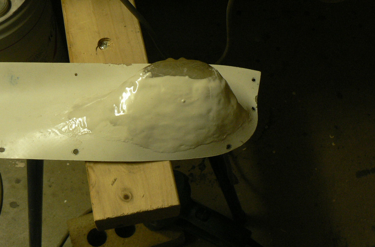
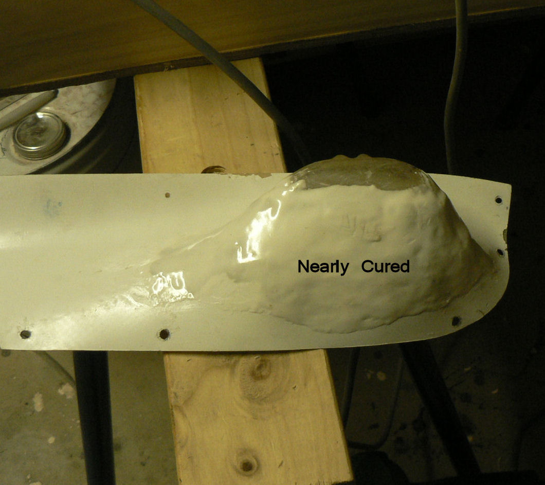
24-09-2007 Filled the chopped up fairing with micro-balls. It is almost cured now at16:00 hrs so should be good for sanding and fitting the strut hole tomorrow although might need a bit more fill to smooth it a bit more. [ATTACH]3717.vB[/ATTACH][ATTACH]3718.vB[/ATTACH][ATTACH]3719.vB[/ATTACH][ATTACH]3720.vB[/ATTACH] [ATTACH]3721.vB[/ATTACH][ATTACH]3722.vB[/ATTACH][ATTACH]3723.vB[/ATTACH][ATTACH]3724.vB[/ATTACH] Had a replacement battery (Ni-MH 3 AHr)for a Dewalt 18V drill that was very hard to detach from the drill. Turned out that the flat springs that retain the plastic clips were not seated properly. A couple of gentle taps on top of the flat spring was enough to seat them correctly. Had to remove the battery cover to get at them.
-
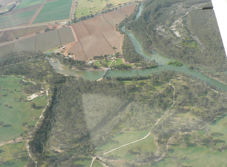
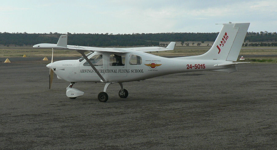
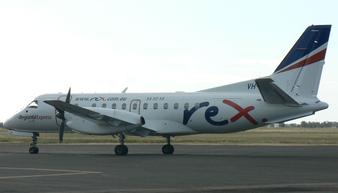
23-09-2007 Got over to Narrandera today and had an aerial fix in the Jabiru J230c with a 40 min fly down the Murrumbidgee with Robert Kirk as co-pilot. Wally Rudin had a student due at 16:00 hrs so we had to be back by then. We were - but the student did not turn up till about an hour later! Rob took some photos for me during the flight plus after tea during a break in the Rugby Union I sanded off the gelcoat off the cured fairing for filling tomorrow with microballs. The first photo is Gogeldrie weir on the Murrumbidgee River downstream of Narrandera abeam about half way between Leeton & Griffith NSW. [ATTACH]3698.vB[/ATTACH]Wally's Jab[ATTACH]3699.vB[/ATTACH]YNAR Traffic[ATTACH]3700.vB[/ATTACH]The sanded fairing[ATTACH]3701.vB[/ATTACH]
-
Hi Fred I don't know you but I know at least you have just completed a low wing AC and you have taken it for its first flight into the air where it belongs! A marvellous pair of goals achieved. A hearty congratulations and may you have many hours of enjoyable flying in your own ........ aircraft. Regards
-
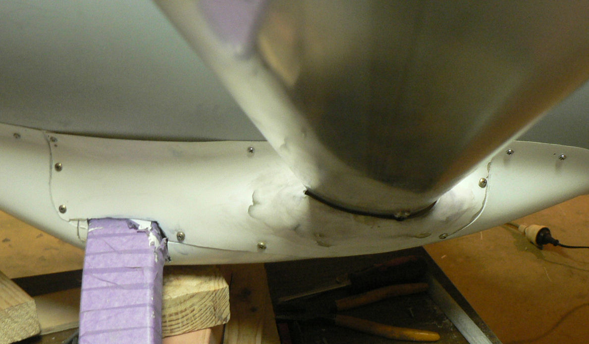
22-09-2007 Modified top half of bottom fairing for RH strut by cutting out material heating and tying it down with lock wire. Then put a number of layers of fibreglass inside the fairing. After that cures I will have to fill the rough bits on the outside, smooth the outside and cut the hole for fitting the strut again. [ATTACH]3690.vB[/ATTACH][ATTACH]3691.vB[/ATTACH][ATTACH]3692.vB[/ATTACH][ATTACH]3693.vB[/ATTACH] Notice the small gap between the strut & the fuselage. The end of the strut near the attaching bolt is actually touching the fuselage skin.
-
Hi JL Your 747 experience reminds me of a similar episode at Leeton quite some years ago. I was assisting manning the club radio during a Gliding Competition probably a State Competition. We were monitoring gliders flying in from surrounding clubs & towns like Forbes, Temora and Narromine. Anyway one pilot had gone quiet on us and we were getting no response to our calls until a 707 I think flying overhead for Indonesia relayed a message from a Forbes based glider. It had out-landed just over the next hill putting him effectively out of range of our ground based radio. I also saw another sailplane coming from the North East fly straight over the top of the airfield at about 5,000 feet. He probably went another fifteen miles or so over the irrigation farms before we got him to turn around. He would have been flying into the late afternoon sun before his about turn! Regards
-
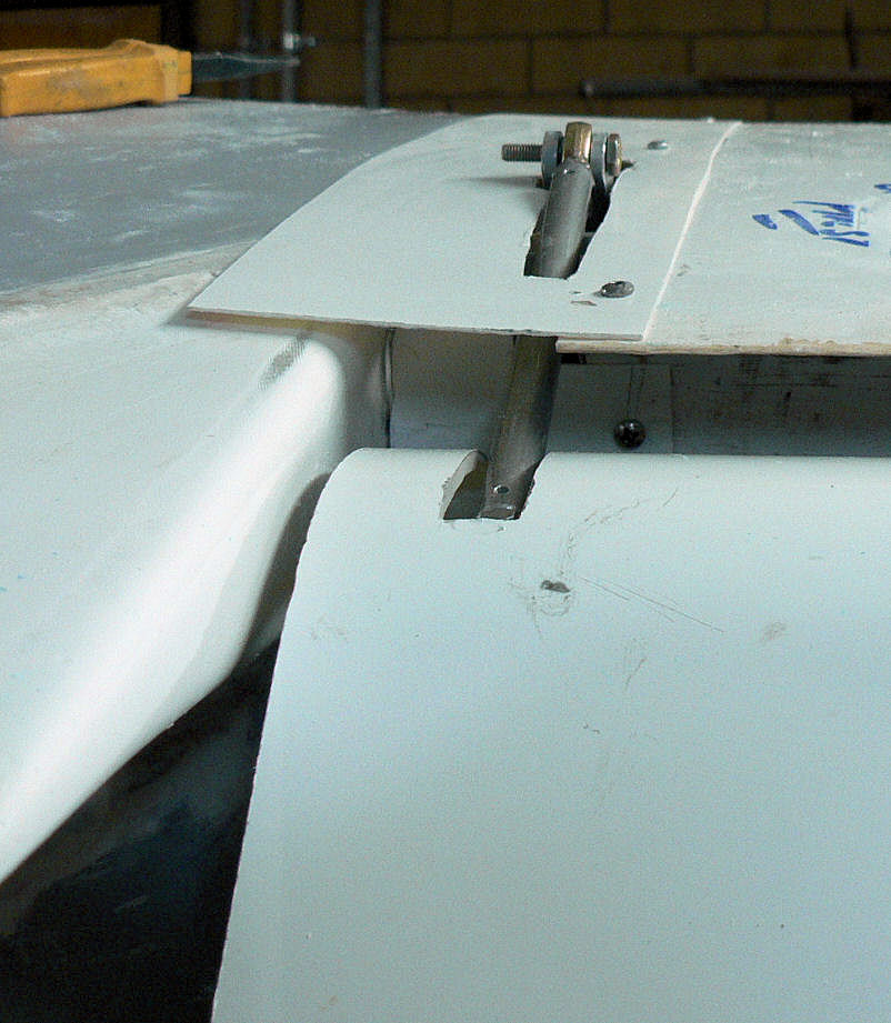
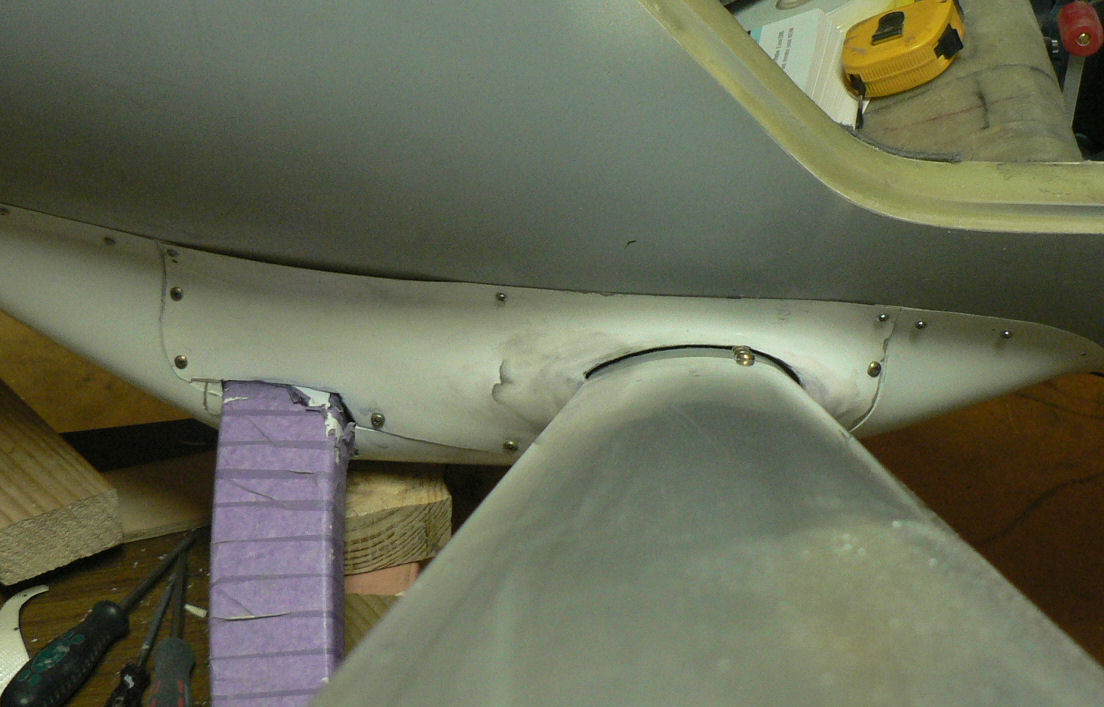
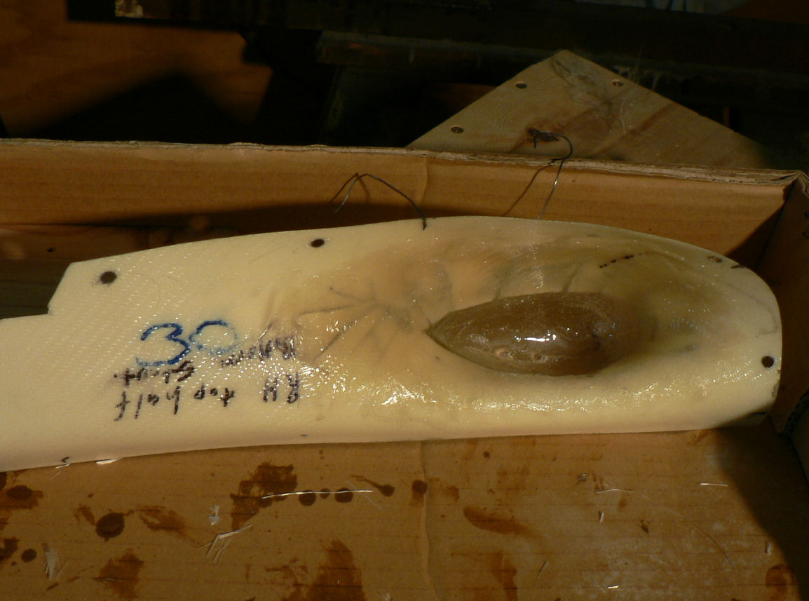
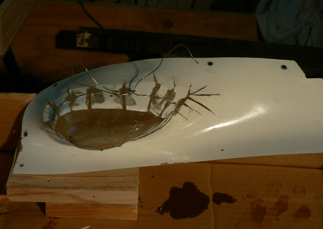
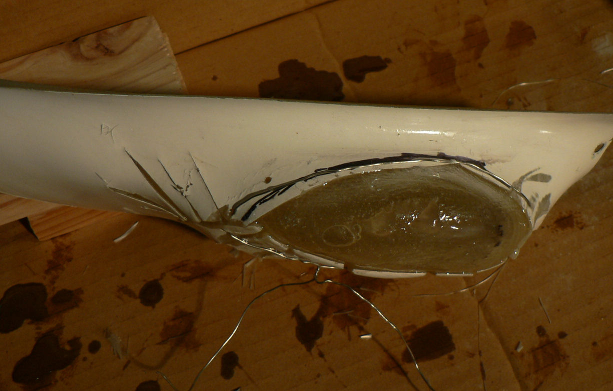
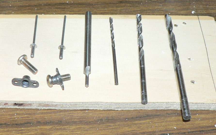
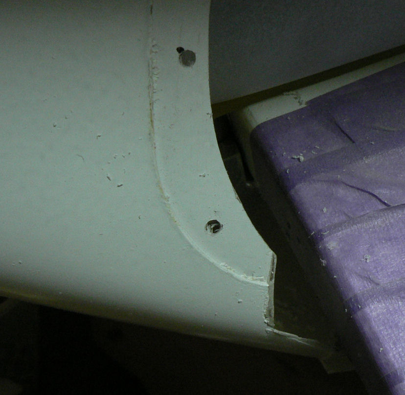
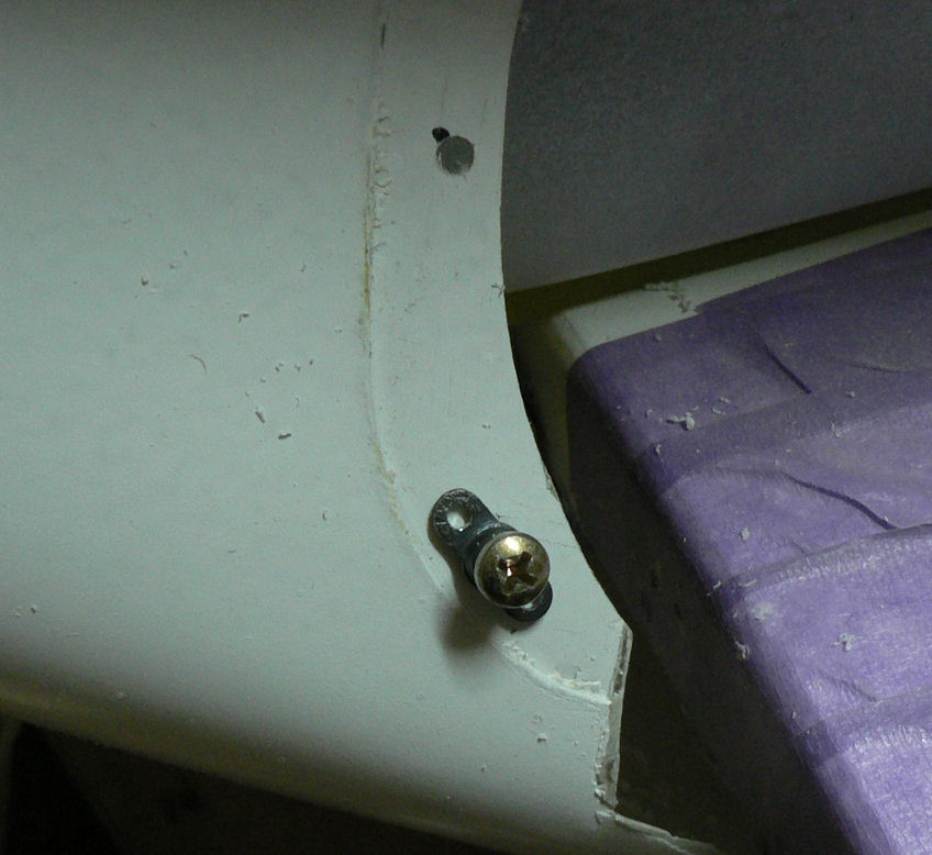
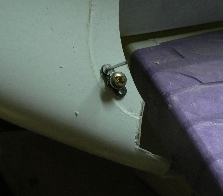
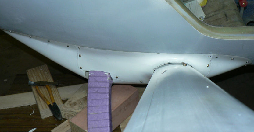
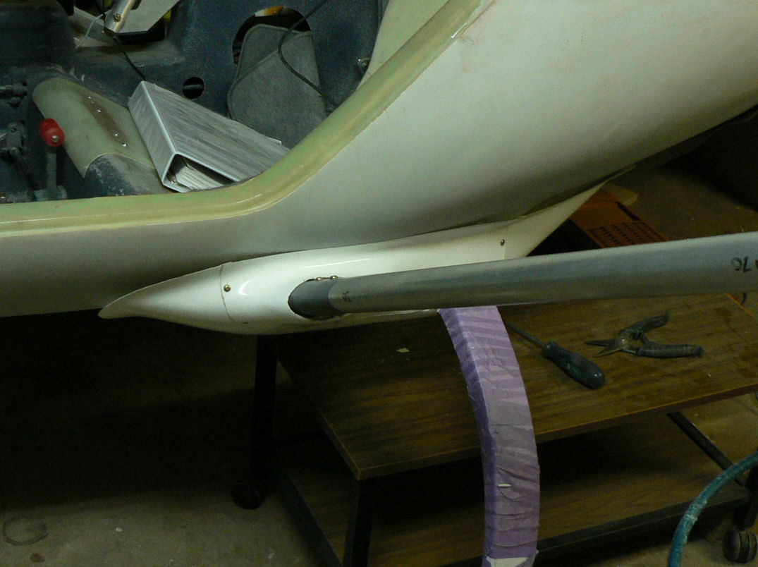
21-09-2007 Did the RH lower strut fairing today. It is going to need a bit more work on it than the LH lower strut fairing as the strut does not fit the area designed for it very well. Aside from the excessive side gap near the UC leg being addressed by filling it in this bad fit problem is not very apparent from the pics shown here. Both problems are being attacked but will take a few sessions of epoxying, filling and filing to improve them. I have mostly used retained nuts to hold the two halves of the fairing together and have done a photo sequence of doing one retained nut. The fairings were set up using SS self tappers and then drilled for the retained nuts and screws with a 5/32" drill. [ATTACH]3674.vB[/ATTACH][ATTACH]3675.vB[/ATTACH][ATTACH]3676.vB[/ATTACH][ATTACH]3677.vB[/ATTACH][ATTACH]3678.vB[/ATTACH] The retained nut with a 5/32" screw is used as a template for drilling the rivet holes at 3/32" which are then countersunk with a 3/32" countersink. After the countersinking all the 5/32" holes were drilled out to 3/16" to give some clearance for the screws. [ATTACH]3679.vB[/ATTACH][ATTACH]3680.vB[/ATTACH][ATTACH]3681.vB[/ATTACH][ATTACH]3682.vB[/ATTACH][ATTACH]3683.vB[/ATTACH] In the last shot shown above the strut - the fairing is too close to the strut and underneath the gap between the fairing and the strut is far too big. [ATTACH]3684.vB[/ATTACH][ATTACH]3685.vB[/ATTACH][ATTACH]3686.vB[/ATTACH][ATTACH]3687.vB[/ATTACH][ATTACH]3688.vB[/ATTACH] The last photo shows a piece being alraldited back in to fill the gap near the UC leg.
-
20-09-2007 A bit more work required here to clean this fairing up later on after I see how the other side goes. Obviously, with hindsight or rather lack of foresight, I do not need the slot for access to the safety belt anchor bolt. [ATTACH]3663.vB[/ATTACH] I am trying to get both sides set up so that the fairings are the same distance from their strut, UC leg and their respective door frame. Have started on the other side and it is more difficult as the clearance between the top half of the fairing and the fuselage is less thus making it difficult to fit it all in. Not a very productive couple of days.
-
Hi Geoff Yes temps are pretty good except that my carport is usually pretty cool in the mornings unless I have done a very late session with the heaters going. Took the day off today with a very short session to fill in a bit of fairing that I had cut out. Repaired with a piece of waste and a couple of drops of araldite. That reminds me that I should go and have another look now. Regards
-
18-09-2007 Not a very productive day. I think I have figured out how to make the fairings fit the bottom of the fuselage, the UC legs and the bottom wing strut. Cut out the hole for the wing strut. Join the two halves of the fairing using only two or three SS screws located along the bottom half of the outside fairing from about half way along the strut and towards the position of the UC leg. Position the last screw near the UC leg about 25 mm from the leg and only on the strut side of the leg. Then concentrate on getting the fuselage side of the fairing to sit neatly on the fuselage and fix it with SS self tappers. This will affect the fit of the outside fairing against the recesses cast into the bottom half of the fairing. Once I am happy with the fit on the fuselage - trim the outside part of the fairing to fit the recess in the bottom half of the fairing. Once it all fits neatly retained nuts & screws can be used to attach the outside fairing to the lower one that is attached to the fuselage. So I might actually get one completed tomorrow except for perhaps tidying up the mess I have made of the first set of fairings. I don't really want to epoxy the bottom half to the fuse as it will make access to some of the seat belt bolts, the UC bolts and legs and the brake lines more difficult.
-
Hi Big Pete It is Kit # 14. I am sure that there were many changes by the time it got to the certified ones. I do not know if the dimensions of the UC legs was one of them. As an example, the certified cabin heater control air valve through the firewall is made in metal, my kit one is made of fibreglass (still on the shelf)! On this kit # 14 at the point where the UC leg exits the fairing the dimensions are 72 mm wide x 32 mm thick measured on top of that tape wrapped around the painted legs. It is certainly bigger than the earlier LSA 55 but how much I do not know. Let me know if your dimensions are different. Regards
-
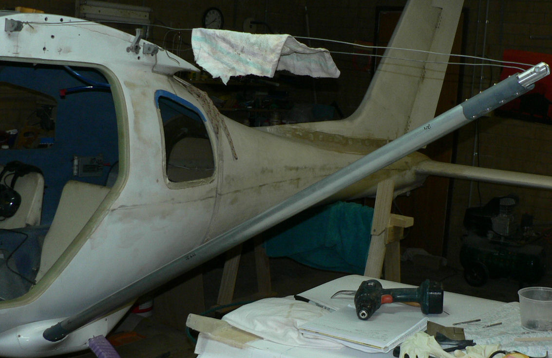
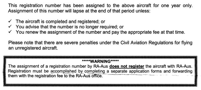
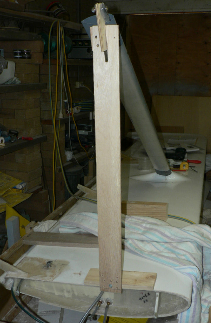
17-09-2007 "The Assigned RA-Aus Registration number is now 19-5162 for one year only. The number will lapse at the end of one year unless:- [ATTACH]3654.vB[/ATTACH] Made up wire strut to simulate the wing connected to the strut to facilitate fitting the lower strut fairings. Connected LH strut to wire struts which puts the strut in approximately the correct angle to simulate the wing in place. Start to pre-fit the lower strut fairings. After cutting out the hole for the strut on what is to be the top removable half of the lowere strut fairing fitted some retained nuts & then tried the fit again. [ATTACH]3642.vB[/ATTACH] [ATTACH]3643.vB[/ATTACH] It is not very neat at the back end at this stage and is going to make access to the undercarriage bolts and the bottom strut bolt more difficult.
-
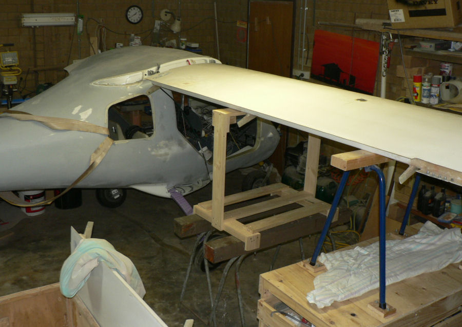
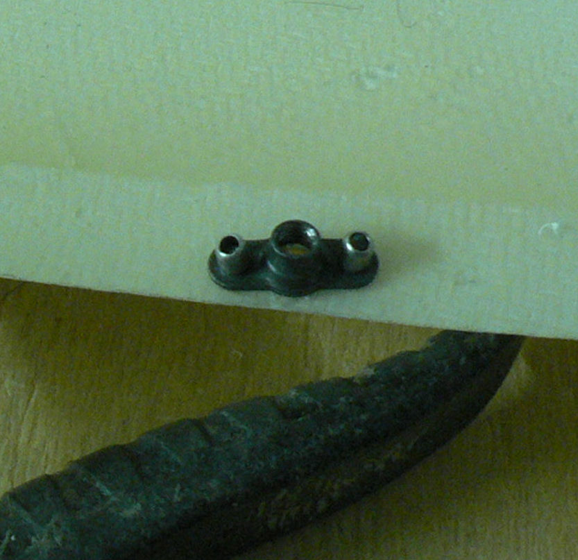
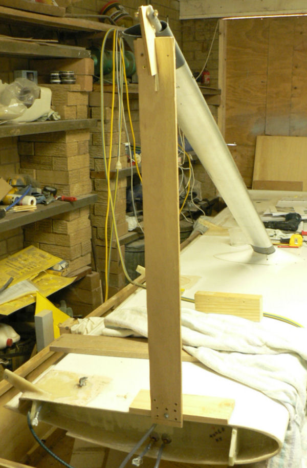
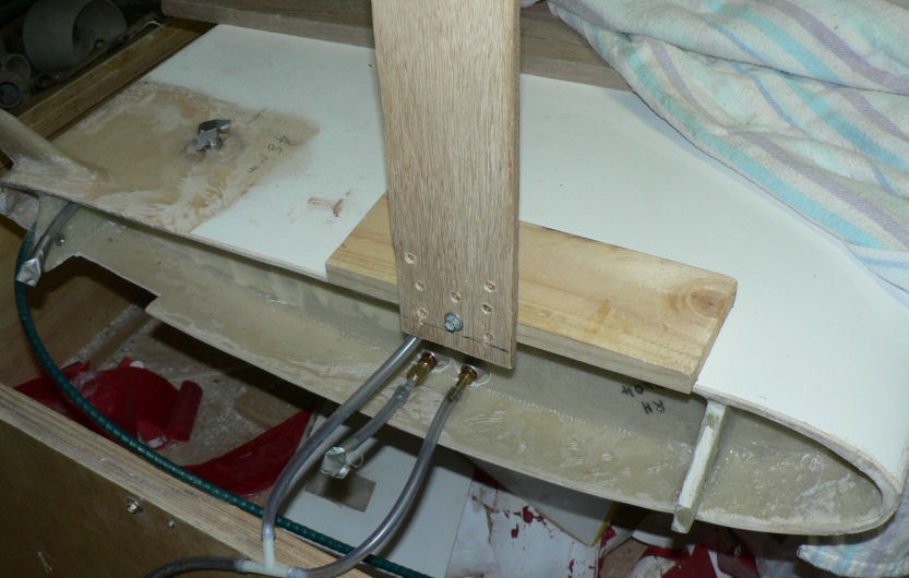
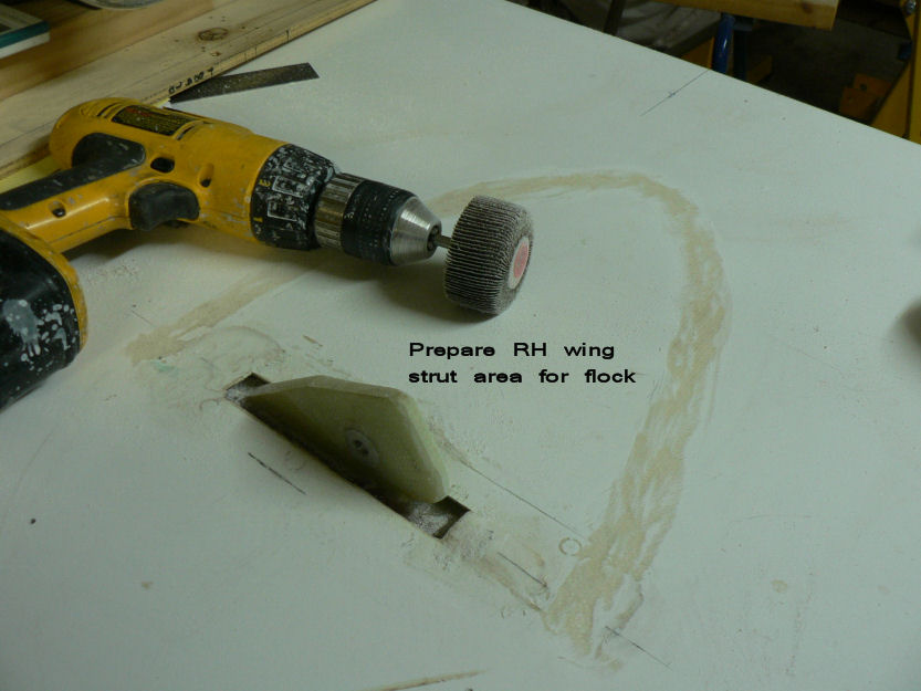
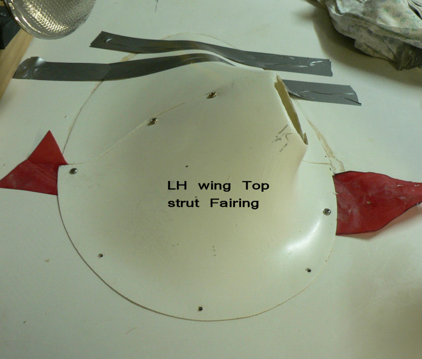
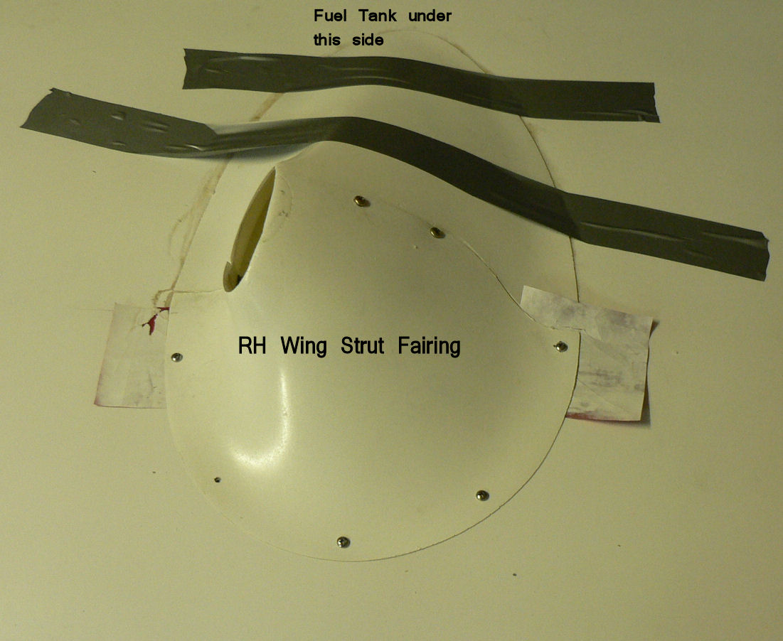
15-09-2007 Simplified the strut support stand so that its foot is sitting on the wing skin - not bolted to the wing brackets. The support can rotate to match the angle of the strut connection and will work for RH & LH wing. Pre-fitted the the upper strut fairing for RH wing & measured up so that it will be a mirror image position wise according to the LH strut fairing position. Some retained nuts were used to join the two halves of each fairing. The Fairing piece that was not below the fuel tank in each wing was attached to the wing by SS self tappers making sure that none entered the fuel tanks. The position of the fairings was marked in pencil on the wing. A strip around this mark on the tank side of the strut was prepared for flock by sanding & cleaning with acetone. The matching fairing for the tank side was also sanded to remove the shine and then cleaned with acetone and epoxy applied to both surfaces. The remaining epoxy was mixed with flock and applied to the fairing for the tank side only of the fairing assembly. The assembly was weighted and taped down to the wing with the excess flock wiped up with an acetone soaked rag. Strut positions marked in pencil and then sanded for the flock connection then cleaned with acetone. [ATTACH]3623.vB[/ATTACH][ATTACH]3624.vB[/ATTACH][ATTACH]3625.vB[/ATTACH][ATTACH]3626.vB[/ATTACH][ATTACH]3627.vB[/ATTACH] Make sure when struts are attached that strut construction nuts are underneath one each side to be replaced with a tie-down lug. [ATTACH]3628.vB[/ATTACH][ATTACH]3629.vB[/ATTACH][ATTACH]3630.vB[/ATTACH][ATTACH]3631.vB[/ATTACH][ATTACH]3632.vB[/ATTACH]