damkia
-
Posts
605 -
Joined
-
Last visited
-
Days Won
3
Content Type
Profiles
Forums
Gallery
Downloads
Blogs
Events
Store
Aircraft
Resources
Tutorials
Articles
Classifieds
Movies
Books
Community Map
Quizzes
Videos Directory
Everything posted by damkia
-
I wonder what model car the engine is from? Look at the air filter on top and the coil near leftmost kid's left hand.... It has actually got a decent coat of white paint on the tail plane too...
-
The technology is cheap enough to do it easily. It wouldn't be that difficult to make retrofit kits available. Phased in over 5 yrs, and mandatory with next panel overhaul and in all new registrations? You've only got to need it once....what price a life? It could be yours.............
-
IIRC - VERY heavy circa 185kg. Better example would be Zoche aerodiesel @84kg for 150HP, although not in production yet (has been a looooong birth) http://www.zoche.de/ I think the main thing holding back the design is in earlier times there was a reluctance to change from Avgas for light aircraft. This is changing with the coming demise of lead in any fuels (including Avgas). Diesels are a lot more acceptable to the general public now thanks to Diamond Aircraft in Europe, and the world is waking up that modern diesels may in fact may be a good thing in aircraft.
-
I would be looking at the valve guides to see if the valve stems are "soft" sticking in the guide art some point, not a hard jam, but a reduction in valve velocity leaving a bit of extra slack in the valvetrain and allowing impact with the piston. This could be from wear of the guides and a valve "rattling" down the guide, or too close a tolerance causing sub critical valve seizure issues in a hot engine. The marking on the piston and lip of the cyl would seem to be an errent valve. The arrow on the piston is used to indicate the correct orientation of the piston when rebuilding, Normally points to the front of the motor. Please note edits to text.
-
Not really as the rocker ratio (ratio of push rod to rocker fulrum, and valve to fulcrum) is what defines how far the valves get sent down the guides assuming that there are correctly set clearances and the hydraulic lifters are working correctly (correct leakdown rate). Changing the camshaft throw would be another fix to achieve the same result. Changing the push rod or cylinder barrels alone would also change the camshaft timing, once again changing the camshaft to adjust for that would put you back at the beginning.
-
No offence meant, but you kinda left yourself open on that one.... Good luck with it and congratulations. Mighty achievement for someone so young.
-
African-Australian Award????? The epic/legendry number of "highs" you have attained? Yep. That'll be it.....
-
I suppose if it was 1st April we could call it an April fools day joke... Seriously though:smash pc: The problem is, it is probably someone with access to an aircraft radio (owner/relative). Reason enough for a lockable isolation master switch to be fitted for all electrics, and a lockable canopy where possible. I would love to see a "selcall" type arrangement that flashed up a fixed radio identity number (like your computer ethernet network card) on your radio display whenever you PTT, that could be cross referenced to an owner, like a GA "squawk". The technology exists as does the ability to store hours of digitised audio data with ID number and GPS positions in real time on every radio in every aircraft (like a black box, but actually inside the radio). If you utilised GPS timing data you could triangulate between airborne sources of the same information (time delays to start of audio) to establish a search point, even if the radio was not a GA comms radio built into an aircraft.
-
Replace one spark plug with a thermocouple on each cyl sequentially for some standing tests?
-
The "Romans" and Greeks have been invading Australia for the last 70 yrs... Wasa da matter you, eh?
-
Bah, humbug Typical space cadets.....
-
Just a few questions about the Joey II 1. Will it take the new Rotax 912 with fuel injection? Rotax 914? Other engine options (Jabs + others - UL Power 130HP)? 2. Are there any specifications/more performance values available on it than what is listed in the website (needs updating?) ie fuel capacity? 3. Anyone have one of these flying yet, and how long did it take to build? This will probably be my choice of aircraft in the next 6 months or so if everything goes according to plan - looking for speed (130K +) as will be used to get to and from work (the ultimate tax deduction?) Gold Coast to Central/North Queensland monthly. Building I am guessing would be in the 400-600 hr range? I still have to get my RAA Lic yet, but that is starting in the next few weeks.
-
Engine Failed, No radio, within gliding distance to airfield
damkia replied to 68volksy's topic in AUS/NZ General Discussion
IIRC this scenario is covered under the CASA rules regarding radio operation into uncontrolled aerodrome, although not specifically during engine failure. I seem to recall something about rocking your wings to indicate a radio failure??? Does this sound right? (it was 18 yrs ago....) -
Known as the bathtub failure curve http://en.wikipedia.org/wiki/Bathtub_curve
-
Another Jab bites the dust.
damkia replied to motzartmerv's topic in Aircraft Incidents and Accidents
Relating to EGT and CHT's As much as I don't believe the reason given by Jab for the failure (ie not living in Bubndaberg etc) they may well be on to something. Could high humidity (northern climes) play a part in keeping the engines cooler than they would be in low humidity? Would it be worth tracking where these failures actually occurred in Australia (or at least where the engines have spent most of their time)? (related to the experiences in the Phillipines per rick-p's post) Anyone that has used water injection in car engines would be familiar with the principle. -
Rotax gets us to Temora and back in fine style........
damkia replied to a topic in AUS/NZ General Discussion
You need a link of cable at the junction of the engine and airframe to prevent engine movement/vibration translating into throttle movement (ie, isolating the engine movement). There is also the issue of resonance/slack of the bars causing potential uneveness of delivery of fuel through changes in throttle, potentially leading to one cyl being leaned out. I'm not saying don't do it, but consider bars for the fixed structures, and cables (enclosed bowden type to minimise effect of vibtation?) for the vibrating parts. But hey, what do I know - I a noob here:wasnt me: -
Another Jab bites the dust.
damkia replied to motzartmerv's topic in Aircraft Incidents and Accidents
IIRC consistancy of manufacture would be good due to the parts being CNC machined. Material consistancy would be the next thing to look at, but I would guess as some of the aircraft engines are certified then there would need to be reasonable QC on the materials with documentation of standards to be met with each batch. Whether the end products designed/manufactured with appropriate materials could be a factor. In military applications I am actually aware of various parts only having a safety factor of about 5% over what they are used at, to maximise the lightness of each part. (old man was RAAF mechanical engineer - his team was the one that "added lightness and simplicated" the F-111 swing wing mechanism for the yanks years ago ) Once again, no expert, or Jab basher, simply someone interested... -
Another Jab bites the dust.
damkia replied to motzartmerv's topic in Aircraft Incidents and Accidents
16" = 4/3ft @12.25lb So for 1 ft it would be 12.25 x (4/3) = 16.333 ft.lb IN THIS CASE (easy way of remembering is to look at what a "ft.lb" represents - how many pounds at how many feet, or simply remember that in maths a "." can also mean "multiplied by") Be aware that there are two types of main errors - zero offset, and scaling. Zero offset means that the scales do not start at a true zero point ( ie a needle with or two either side of zero). Scaling is is a linear inaccuracy (ie as if you were measuring things on the moon - less gravity affects all readings by an equal percentage). The best idea if you are serious is to do three series of three different settings on the torque wrench, ie, 10 ft.lb (x3), 30 ft.lb (x3) and 50 ft.lb (x3) and post up the figures you get from your scales. From this you can draw a "line of best fit" on a piece of graph paper and extrapolate all points in between. There are more obscure errors but not really appropriate in this discussion (parallax errors in viewing scale from an angle, etc), and of course the obvious of the accuracy of the scales you are pulling on (with their zero offset and scaling errors...). -
Site doesn't appear to be loading... Post up details?
-
Another Jab bites the dust.
damkia replied to motzartmerv's topic in Aircraft Incidents and Accidents
On such a critical component such as the through bolt I would have thought it prudent to have a maximum number of times it can be used (torqued up) before replacement (ie replaced every 5 or so re-torques). Whilst it may not be a directive of Jabiru, it may be worthwhile approaching them to do some real life trials of periodic replacement with new bolts, even with the new larger bolt solution they have started to use. The worst that can happen is the problem is fixed. The big problem I see with these bolts would seem to be that they are retorqued too often coupled with a bit of resonance along their length ("guitar stringing"), stretching them each time until the metallurgical properties of the steel change from elastic deformation t0 plastic deformation and fatigue, and they fail. This would generally be seen as the bolts not being shiny, but have a slightly grainy appearance inthe shaft, especially at the stress riser of the junction of the thread to the shaft of the bolt and under the head of the bolt. -
Another Jab bites the dust.
damkia replied to motzartmerv's topic in Aircraft Incidents and Accidents
Thank you for the full explanation. -
Another Jab bites the dust.
damkia replied to motzartmerv's topic in Aircraft Incidents and Accidents
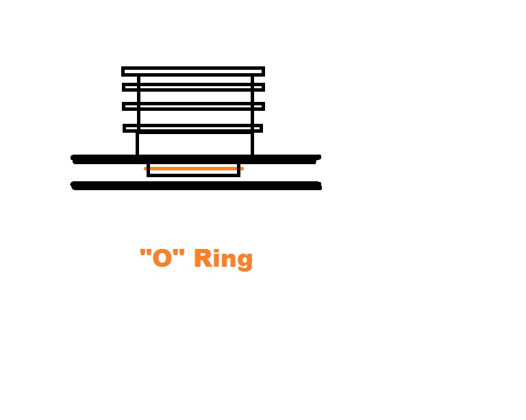
Why not use an "O" ring (of silicone?) in a groove around the base of the barrel where it "plugs in" to the crankcase, allowing the flush mating surfaces under pressure to come together sans silicone, and using the inner part of the crankcase hole and outer barrel as the oil sealing surface? Seems to be a far more elegant way of doing it...
-
Another Jab bites the dust.
damkia replied to motzartmerv's topic in Aircraft Incidents and Accidents
An interesting comparison of failure rates is that of the nitro funny cars. Apart from "idling" (well, more "failure to stall"), they have a life of perhaps a half a dozen runs before catastrophic failure or strip down and rebuild. Consider this: they do a quarter mile in (say) 6 seconds = 1/10 minute, at 8000 rpm WOT = 800 revolutions per WOT run. Multiply this by the half doz runs and you have an engine that lasts less than 5000 revolutions at full power, or 1.5 mins equivalent for a Jab, and 1 minute for a Rotax. -
Another Jab bites the dust.
damkia replied to motzartmerv's topic in Aircraft Incidents and Accidents
Not at 75-100% power continuously though.... As previously noted most automotive engines are lucky to see one to two short bursts of WOT in a day. More work = more wear. -
Another Jab bites the dust.
damkia replied to motzartmerv's topic in Aircraft Incidents and Accidents
A few more things.... Out of curiosity, have the bolts been re-tensioned by way of removal and rebuild? Could they in fact be a "torque to yield" bolt that is designed to be single use? Could they have accidentally been used (designed) in a yield situation where they are in fact overstressed (seems utterly possible)? One more thing, would it be possible to do a dye test for cracks around and through the bolt hole in the pot and crankcase? Is there is a possibility that there may be a bit of crush deformation of the hole allowing metallic "hammering" of the bolt? Yet another possibility from left field is resonance of the bolt itself at particular engine revs causing metal fatigue. Torque to yield style bolt/stud is commonly used in automotive head-block assemblies. Having said that there is also a common issue in (of all things) Mazda rotary engines where the long steel through bolts expand at a different rate to the aluminium housings causing similar issues if not torqued correctly with new bolts used each time causing the alloy to crush. This also happens with wheel studs and nuts and alloy rims that have been overtightened with a rattle gun (the reason they give you a ridiculously short wheelbrace - so you can't over-tighten them by hand when out on the road).