Dafydd Llewellyn
-
Posts
1,513 -
Joined
-
Last visited
-
Days Won
43
Content Type
Profiles
Forums
Gallery
Downloads
Blogs
Events
Store
Aircraft
Resources
Tutorials
Articles
Classifieds
Movies
Books
Community Map
Quizzes
Videos Directory
Everything posted by Dafydd Llewellyn
-
Propeller breaks at 13,000 feet
Dafydd Llewellyn replied to ayavner's topic in Aircraft Incidents and Accidents
Yes, indeed. In recreational aviation circles, some people seem to regard the propeller as some sort of fashion accessory. The reality is that propeller failure is just one notch less disastrous than losing a wing. -
Braking ideas
Dafydd Llewellyn replied to Deskpilot's topic in Aircraft Building and Design Discussion
Nev, I agree, having owned several Austers - but the problem with the Auster heel brakes has two causes, neither of which is a result of the basic principle: Firstly, the brakes themselves were Bendix "duo-servo" drum brakes, and without going into too much detail, they are the worst possible design for brake fade. Secondly, the operating cables turn through a right angle in guide tubes under the floor. Over time, the cables wear a groove in the wall of the tube, at the bend. But the cable wears also, so the groove is just a bit undersize to fit a new inner cable. So, when the brake cable need replacing - somewhere around 2000 hours TIS - the new inners will lock in the worn grooves, and the harder you push on the pedals, the more firmly the cables jam in the grooves. Combine the two effects, and an Auster becomes impossible to taxi in a crosswind. The heel brake concept has a lot going for it in my view - but it does need to be properly engineered. However, most people just fit toe operated hydraulic disc brakes and have done with it. -
Propeller breaks at 13,000 feet
Dafydd Llewellyn replied to ayavner's topic in Aircraft Incidents and Accidents
OK, you have, say, a 60 inch fixed-pitch wood propeller that weighs four pounds, turning at 2700 RPM. The centre of gravity of each blade will be somewhere about one foot (300 mm) from the axis of rotation. What's the centrifugal force at the centre of the propeller hub? The formula for the centrifugal acceleration is radius x (speed of rotation squared); the speed of rotation in radians per second. 2700 RPM = 45 revolutions per second. There are 2 pi radians per revolution, so that's 283 radians per second. So the centrifugal acceleration is 1 x (283 squared) = 80,089 ft/sec^2. 1G = 32.2 ft/sec ^2, so that's 2487 G acting on the blade - so the force will be 2487 x the mass of the blade (2 lbs) = 4974 pounds force, i.e. 2.2 tons. The engine mount is stressed for 1.5 times the engine weight, acting sideways - so for a 180 lb engine, the mount will be designed for a limit side load of 270 lb Force; and the required factor of safety is 1.5, so it will break at a bit over 405 pounds force, i.e. a bit less than 1/4 of a ton, under the side load. It's also stressed for around 6 times the engine weight, vertically down, i.e. around 1080 lbs force. Either way, if half the propeller departs and the other half stays on the engine, the engine is almost certain to part company with the aircraft. This tends to result in the CG being not where the designer intended, so you get a short and very interesting ride. Fortunately, when a fixed-pitch wood propeller fails, it almost always does so in the middle in such a way that both blades depart virtually simultaneously. This is one of the reasons I like fixed-pitch wood propellers, especially certificated ones. -
You're very far from being the only one!
-
Any retractable- gear aircraft has the potential for a gear-up landing, for a variety of causes apart from pilot error. What surprises me is that so few of them incorporate a rub-strip or two on their belly*, to reduce the damage; or leave a part of the main wheels extended. But no, they seem to want to retract the gear sideways, and pull it all the way in. The small gain in performance from that, over the way Douglas did it in the DC-3, is important if you are actually in combat, where every ounce of speed counts - or if you are flying a high-altitude spyplane, where the drag may cost a bit of service ceiling. But in a recreational aircraft? * The Boulton-Paul Balliol advanced trainer had a sprung skid incorporated in its fuselage; one of the very few whose designers seem to have thought about this. It reminds me of the pattern of aircraft ownership that emerged amongst well-heeled owners in the '60s - their first aircraft was similar to what they trained on; the second was a retractable, with two engines for the really affluent ones, and the third one was single engine, fixed gear, but with sufficient disposable load to be useful - e.g. Cessna 206 or Cherokee six. One of the things one needs to watch for, in a retractable, is that no fuel drain valves project where they are liable to be damaged in a wheels-up landing. That's a requirement for certificated aircraft.
-
Tends to be more expensive than that, in a Lancair of that generation, because sliding along the bitumen tends to abrade the wing main spar cap.
-
Small aircraft crashworthiness
Dafydd Llewellyn replied to Dafydd Llewellyn's topic in AUS/NZ General Discussion
Nev, I agree; and a fuel shut-off valve within the pilot's reach is a requirement for just about any certification standard. The multiple fuel valves one sees in some amateur-built versions are not acceptable for certification. The Citabria was a CAR 3 aircraft; CAR 3.625(b) contains the same requirement as FAR 23.1193(d).. I recall the Citabria did have metal skin on the fuselage underside, back to the undercarriage (it was openable, as an access panel). I flew a 7GCBA and the 8KCGB (if I have those numbers right) at Tocumwal; and a friend owns a 7GCBC, so I'm tolerably familiar with them. You can't pick a fire-retardant resin by its appearance, normally. Fire is something a lot of people turn a blind eye to, possibly because it's too horrible to contemplate. This is foolishness; with a little thought, the risk of an in-flight fire can be vastly reduced, and the survivability vastly increased. It gets a lot of attention in certification, but only to the level demanded by the relevant standard. One of the things I do not like about the Rotax 912 is that the fuel system is above the engine. That's an unnecessary fire risk, as was proven by the Continental IO-360. The optimum engine layout for fire risk is exhaust on top, fuel system underneath - and the Navajo and Cessna 400 series are set up that way. However, cowl outlets ahead of the windscreen are not unknown, amazingly. Somebody must be insane . . . -
Small aircraft crashworthiness
Dafydd Llewellyn replied to Dafydd Llewellyn's topic in AUS/NZ General Discussion
Yep, ablation is the term you want - the trick is to form a strongly-adhering layer of char, which acts as an insulator. The use of hydrated aluminium oxide works that way, as far as I can see. The term "fire-retardant" in respect of resins systems seems to mean that they do not themselves support combustion, but slowly char. There's very little evidence of real thought in regard to fire resistance, in most small aircraft cowl designs. -
Small aircraft crashworthiness
Dafydd Llewellyn replied to Dafydd Llewellyn's topic in AUS/NZ General Discussion
How thick was the layup? In a massive (by comparison with a typical aircraft cowl) layup, the temperature of the laminate can be controlled for a while, by the use of hydrated aluminium oxide powder in the resin - around 50% by weight. The latent heat of vaporisation of the water is quite effective - while it lasts. Also, you do not have a tornado of air inside the tanker, as you do inside an engine cowl, so there won't be sufficient oxygen to get a really hot flame inside. So not really a valid comparison. Most readily-available fire-retardant or heat-resistant resins I've come across are getting pretty hot and bothered at around 300 F. "Fire-resistant" requires 1100F. You may be able to get better than this, but it won't be available in small quantities. Derakane 510A plus 15% W/W of Antimony Trioxide just managed to meet the FAR 23 requirement, but it was largely char by the end of the test, with barely any structural strength remaining. -
Small aircraft crashworthiness
Dafydd Llewellyn replied to Dafydd Llewellyn's topic in AUS/NZ General Discussion
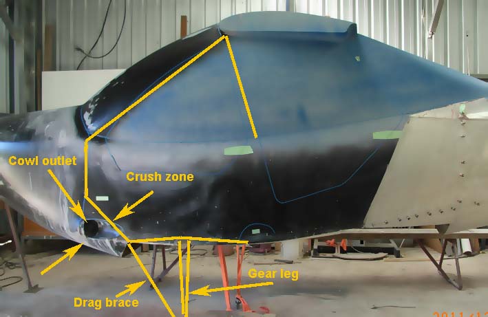
Ha - I assume your concern is that in the event of an engine fire, the fuselage skin aft of the firewall needs to be fire-resistant? Let's talk about that, because it has both primary and secondary safety aspects: Firstly, there is a requirement in FAR 23 and CS-VLA that the fuselage skin directly behind any cowl outlet (by which is usually understood, any area of skin likely to be affected by flames coming from the cowl outlet) for a distance of 600 mm aft of the outlet, must be at least as fire-resistant as normal aluminium alloy aircraft skin (FAR 23.1193(d) or CS VLA 1193(d)). That is normally addressed by adding a piece of metal skin in that area outside the GRP skin. (There is no such requirement in most of the recreational aircraft standards.) Secondly, the cowl outlets in my aircraft are pieces of 0.016 inch wall stainless steel tube - i.e. they are in a regulatory sense, parts of the firewall. What you see in the photos is the chute in the fuselage skin plug to cater for them. The stainless steel tubes finish about 3/4 of an inch clear of the skin. Thirdly, an engine cowl is supposed to be as fire-resistant as aluminium alloy (23.1193©); again, that's not carried over into most recreational aircraft standards. Containing an engine fire in an aluminium-alloy cowl is rather akin to boiling water in a paper bag; it depends upon the cooling supplied by the external airflow to prevent the cowl from melting. This makes the use of GRP cowlings an interesting question; in the past, people simply used a "fire-retardant" resin and added 15% of Antimony Trioxide to the resin, and let it go at that. But any GRP resin is an organic material, and it is not truly fire-resistant to the extent that aluminium alloy can be when it is cooled on the non-fire side; and GRP is a much less effective conductor of heat, so cooling the outside is not particularly effective. A single-engine aircraft requires a "fire life" of the cowling of 15 minutes (look up the definition of "Fire resistant" in FAR Part 1). That is likely to require something additional to a bare GRP cowling; there are various approaches - one could glue Fibrefrax blanket to the inside - if one had a truly fireproof glue - but the insulation must not be able to absorb spilled fuel or oil, so that won't answer. Intumescent paint sounds good, except that it's likely to fall off when it chars, rather than remaining in place to protect the cowl. I've not seen anything that I'd consider a truly fire-resistant engine cowl on any recreational aircraft. I have some ideas on this, but not yet tested. At least, the cowl outlets on my aircraft are visible to the pilot. -
Small aircraft crashworthiness
Dafydd Llewellyn replied to Dafydd Llewellyn's topic in AUS/NZ General Discussion
I used Microsafe, which is an old DOS - based FEA program. I did the analysis almost a decade ago. -
My BIG Lottery Win on the weekend!
Dafydd Llewellyn replied to Riley's topic in AUS/NZ General Discussion
If it's the type that has a loose flange, retained by a large wire circlip (as was used on the PA 18), they are notorious for cracking in the base of the circlip groove. If it's one of those, I'd look into fitting a standard Cleveland 600 x 6 wheel with 800 x 6 tyres. -
Or another qualification that is appropriate for the class of aircraft.
-
I would question whether this is in fact correct.
-
Small aircraft crashworthiness
Dafydd Llewellyn replied to Dafydd Llewellyn's topic in AUS/NZ General Discussion
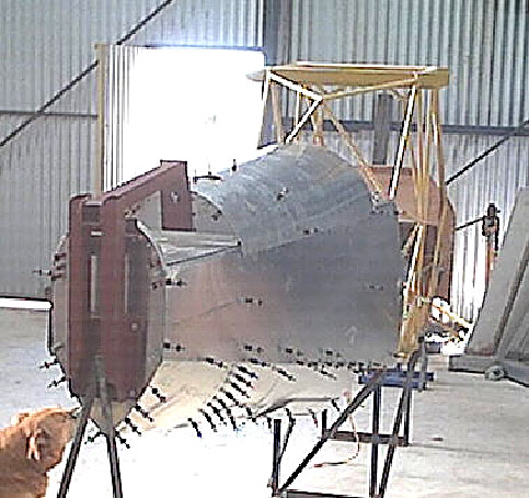
Those photos are of the plugs for the fuselage moulds, so naturally no proper firewall in there at that stage. Yes, there will be a conventional stainless-steel firewall, extending to the lower skin, with fibrefrax backing. Attached a shot of the rear fuselage, for your interest - the sheet metal bit weighs 30 lbs. There's a vapour barrier between the pannier and the cabin. I'm not trying to sell you the aeroplane; I'm trying to illustrate how some of the secondary safety feature identified in this thread can be incorporated into the design of a small aeroplane. It's designed for certification under CS-VLA, so of course it has all the safety features demanded by that standard.
-
Small aircraft crashworthiness
Dafydd Llewellyn replied to Dafydd Llewellyn's topic in AUS/NZ General Discussion
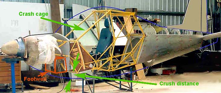
That crash cage of mine is actually the aircraft primary structure; it's essentially a 25G cage but it also carries the undercarriage, the engine mount, the wing and lift-strut, and the rear fuselage. The skin of it is largely removable for servicing; and since it has "stroker" seats, the control circuitry runs outside the steel frame, between it and the non-structural skin. The total weight of the yellow frame in those photos is 56 lbs. It's "fail-safe" to some extent; the analysis covers a number of single-element failures. The aircraft has two seats in tandem. The detail of the frame is not evident in those photos, but it can certainly deal with the FAR 23.561 inverted case (3 G inverted). The analysis showed that a "spider" is needed in the windscreen aperture, to minimise local bending stresses at a number of cluster joints; however it has to be made from non-magnetic material , and so is not in the photos. -
Small aircraft crashworthiness
Dafydd Llewellyn replied to Dafydd Llewellyn's topic in AUS/NZ General Discussion
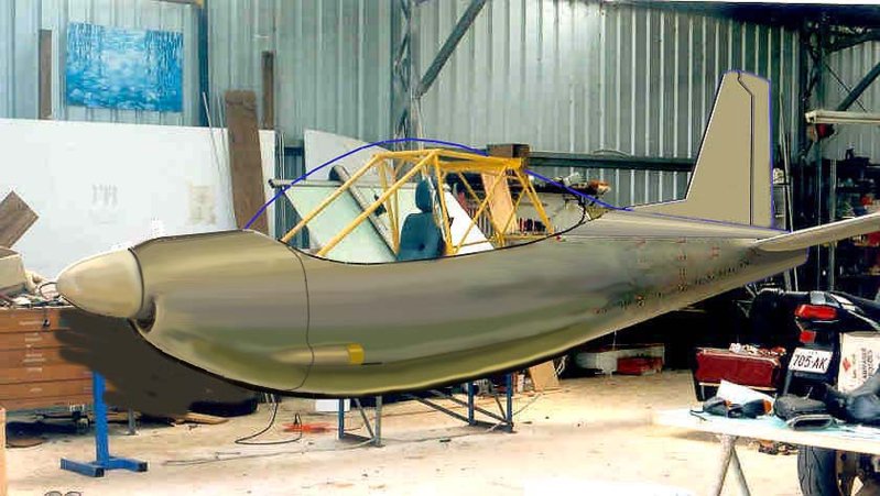
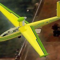
Some of you may find the attached of interest. The third image is a photoshop drawing, but the real thing looks very much like that. It has a faired-in cargo pannier underneath the crash cage, which can (provided it's not loaded with hard objects) provide some eight inches of crush capability. The pilot's footwell also contributes to the crush capability; the rudder pedals are designed to move rearwards as it crushes, carrying the pilot's feet with them. This fuselage has the major features identified in the thread. I don't see how to achieve more than this without the design getting silly.
-
Small aircraft crashworthiness
Dafydd Llewellyn replied to Dafydd Llewellyn's topic in AUS/NZ General Discussion
Well, if it forms a strong film that shrinks and thus pre-stresses to concrete block in compression (and the porous surface of the block is ideal for that), then it takes advantage of the compressive strength of the block, and overcomes the very low tensile strength of unreinforced concrete. However, that's the reverse of what we have in s typical fuselage structure; the shell is quite strong in tension, but weak in compression, because it buckles. So you might find that a coating of that nature rather less effective than that video would lead one to expect, on the impact resistance of an aircraft fuselage. Of course, it would make the pieces easier to find . . . -
Two things to watch out for in an "on condition" engine, especially if it's over the recommended calendar time: (1) Corrosion inside the front end of the crankshaft, where fixed-pitch propellers are used. The only way to check this is to remove the welsh plug from the centre of the propeller flange, and take a good look inside. Got your LAME to do that and to replace the plug with a new one afterwards. (2) With small Lycomings - look for oil getting into the starter motor. If the starter is covered with black oil, the centre crankcase joint on the engine is starting to "work". That's a sure sign it's time to overhaul.
-
Small aircraft crashworthiness
Dafydd Llewellyn replied to Dafydd Llewellyn's topic in AUS/NZ General Discussion
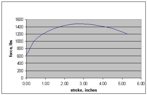
Quote: "If the seat is on top of the deforming structure, then in a vertical deceleration, surely some weight may help it begin the deformation? As your mass and that of the seat would be moving as one." Once your mass and the seat are moving as one, yes. However if you had, say, a three inch cushion on top of the seat (not uncommon when a woman wants to see over the instrument coaming), your body will collide with the seat quite hard before the seat starts to move. This showed up in the various impact tests. This is why people need to read and understand the technical data before setting out to "improve" their seats. Attached is the force curve I expect to see from my "folding parallelogram" seat base. As you can see, it has a "soft" start. This is the force produced by plastically stretching two pieces of soft stainless-steel rod; the shoulder harness adds something to this, increasingly towards the end of the stroke. There's another issue with seats that use a deforming metal element (e.g. the S-bend seat legs on the Cessna 208), and that is, that the deforming elements must get fairly close to their yield stress in flight if the aircraft is manoeuvring hard or in turbulence; and that means they eventually start to develop fatigue cracks; I think you will find there's an AD on Cessna 208 seat legs for this reason. It needs clever design to avoid this. In regard to the overall summary by HITC, I think it's important to put the various items listed into the following context: The FIRST step is to achieve a non-deforming cockpit structure. The idea of any form of "crash cage" in any form of vehicle, is to keep the immediate space in which the body moves under impact, free of hard objects. Everything outside the crash cage should, if possible, act as energy-absorbing material; but since energy absorption is the product of the crushing resistance of the material and the distance it crushes under that load, the scope for that is very limited in a small aeroplane. The main object of motor vehicle barrier-crash testing is to demonstrate that the cabin does not deform significantly, up to the limit specified. Until you have achieved a non-deforming cockpit, none of the other secondary safety devices is going to achieve anything, really. The SECOND step is to absorb the velocity of the crash cage without exceeding its structural capability. Since we can't do this by building a long, crushable snout on the thing, we have to do things to allow the aircraft to skid along the ground rather than to dig in. So the detail design of the lower front corner of the crash cage is absolutely critical; the "bevel" needs to act like a belly-board on steroids. Also, the stall behavior needs to be such that the aircraft does not pitch nose-down and spear into the ground - although that's a piece of primary safety, but it's of vital importance in an emergency landing situation. The THIRD step is to use any or all of the things in the summary, to prevent the occupant from colliding with the crash cage itself. THIS is where safety harness, air bags, temperfoam etc all come into play. They are a waste of time, pretty much, unless they are used in this context. I should add - a fully-triangulated steel space-frame makes an excellent non-deforming structure, and it's not particularly heavy - but when it does collapse, it absorbs little energy. The cabin structure of the Jabiru does absorb significant energy by minor elastic deformation, and to that extent it is arguably superior to an equivalent rigid steel space-frame; however designing such a structure is largely a matter of trial and error, so unless you have a dynamic test facility handy, it's very difficult to beat a welded steel space-frame for the crash cage.
-
Small aircraft crashworthiness
Dafydd Llewellyn replied to Dafydd Llewellyn's topic in AUS/NZ General Discussion
Turbs, you will find data on the accelerations that a human body can stand in the reference for which I gave the link in post #86. It's also given in the USAF Crash Survival Design Guide, and in the early Vulcan and Sarraihle report, for which I have not been able to find a link so far. This work goes back to the NACA rocket-sled research performed by Colonel Stapp, in the early 1950s. http://en.wikipedia.org/wiki/John_Stapp We do not need to infer it from road or race car practice, although some of the design techniques devised in racing may be of value. -
Small aircraft crashworthiness
Dafydd Llewellyn replied to Dafydd Llewellyn's topic in AUS/NZ General Discussion
Yes, very good thinking. A lot of those aspects are in the area of primary safety - i.e. accident prevention by design - which should really be the next major thread on this overall safety subject. However there is a bit more to be said on the subject of spinal protection: The first requirement has been defined by the various authorities as limiting the compressive force in the lumbar spine to not more than 15 00 lbs force, whilst reducing the body's velocity in the direction parallel to the spine from 31 feet per second to zero; so the problem is one of energy absorption (i.e. force times distance) with an upper limit on the force involved. Various of the research efforts that are documented in the bibliography of the report whose link is in post #86, show that the dynamic response of the aircraft structure, the seat structure, and any cushions between the pilot and the seat, can all have major modifying effects on the spinal load/time history; and for that reason, the authorities require a dynamic test using an instrumented dummy* fitted with a load cell at the base of its "spine" - in other words, in this particular area, the design requirement has not been reduced to a simple, readily measured "code", but it instead a prescription for what amounts to basic research. People doing such tests have been able, by "fine-tuning" the seat structure and a temperfoam cushion, to meet the 31 ft/second impact requirement without having to resort to a "stroker" seat. The Whitney Boomerang seat is one example; it achieved the result by allowing the temperfoam cushion to partly extrude through calibrated perforations in the seat pan. It is not clear to what extent this sort of thing constitutes complying with the letter of the requirement rather than the spirit of it; after all, the intent of FAR 23.562 was to provide an overall level of protection against a wide range of impacts; tailoring a minimal system to just comply with the precise impact conditions prescribed for the design standard may not provide good protection for impacts in general; insufficient research exists at present to answer that question. It is known, from the research, that adding a soft cushion over the top of either a "stroker" seat, or of one of the "finely-tuned" rigid seat systems, can completely nullify the protection provided by the seat, because it introduces a "secondary collision" - between the pilot's backside and the seat. "Energy-absorbing" foam tends to be decidedly on the hard side for comfort; but it is unwise to add more than 25 mm of soft "comfort" cushioning over it. A real "stroker" seat with around 150 mm of travel or more, can overcome these secondary effects to a considerable degree, provided it is sufficiently light that the inertia of the seat itself does not overload the pilot's spine in order to start the collapse process. Such a seat brings with it issues of maintaining harness tension, and avoiding injury from the controls - so it becomes a very considerable design challenge in its own right. Thinking about ways to design around these issues may well be less costly than throwing money at impact sled testing. * A very expensive instrumented dummy - around $35K if you can get hold of one - but they were out of production, last time I looked. -
Small aircraft crashworthiness
Dafydd Llewellyn replied to Dafydd Llewellyn's topic in AUS/NZ General Discussion
I suggest you read this first: http://www.dtic.mil/dtic/tr/fulltext/u2/a221557.pdf -
See http://services.casa.gov.au/airworth/airwd/schedules/ad_display.asp?session=422775566&pc=PC_90822&sched=Enggen&toc=ENG and look at AD/ENG/4
-
Small aircraft crashworthiness
Dafydd Llewellyn replied to Dafydd Llewellyn's topic in AUS/NZ General Discussion
I imagine - I don't KNOW - that an airbag might be a substitute for a hans device or equivalent head-neck support - and indeed if you use a crash helmet, the added mass of the helmet makes neck injury more likely in a sudden deceleration event. However, that's supposing the major impact is "on the nose" (as in a motor vehicle). The aircraft requirements for impact testing are more directed towards impacts from below. I do know that the impact testing for the Whitney Boomerang showed that whiplash protection is necessary (i.e. a headrest behind the head). However an air bag cannot cope with multiple impacts, whereas a full safety harness with a hans device can. If one were flying low-level air racing or something like the Red Bull air racing, I expect going to this extent would be advisable. However it will not protect your spine from an impact from below; and it does little to correct basic structural collapse of the cockpit; so I would not consider it a substitute for proper basic crashworthiness design. Simply designing the lower front corner of the firewall so it slides rather than digging into the ground, would achieve at least as much benefit as airbags, I would imagine. I'd advise people not to purchase aircraft that have obvious design deficiencies of this sort, rather than trying to compensate for the deficiencies by the addition of airbags. We all make compromises in these regards - I'm setting up a Blanik, which has anchorages for 9 G four-point harnesses, and no possibility of more than about a 2 inch cushion of temperfoam. I'm counting on the primary safety. But at least I understand what I'm choosing. I hope this thread will help other people to understand what they choose.