Dafydd Llewellyn
-
Posts
1,513 -
Joined
-
Last visited
-
Days Won
43
Content Type
Profiles
Forums
Gallery
Downloads
Blogs
Events
Store
Aircraft
Resources
Tutorials
Articles
Classifieds
Movies
Books
Community Map
Quizzes
Videos Directory
Everything posted by Dafydd Llewellyn
-
 You could hardly find anybody better than Keith.
 -
Nev, I've never come across a real professional test pilot who was any sort of "ace of the base", no matter what his manner might be. If you look at CASR 21.037, anybody can act as the Applicant's test pilot - but if the applicant wants CASA to take the Applicant's Flight Test Report seriously, he had better use a pilot that CASA recognises as competent. CASA will not even come and look at the applicant's aircraft until they have received the applicant's FTR and assessed it. The ability to write an intelligible test report is part of that. Real test pilots are cautious and methodical about what they are doing; and nowadays often have both formal test pilot training and an engineering degree. I do not see how an amateur builder, unless he has this sort of background, can hope to match that. To answer another post - the test pilot generally chooses whether or not to wear a parachute, depending on the nature of the test. I always wear one for flutter testing and spin testing; I may or may not wear one for other testing depending upon what I see as the level of risk. The use of a spin recovery parachute and a personal parachute is usually mandatory for spin testing, in the conditions imposed on the experimental certificate.
-
Has anybody tried asking an experienced test pilot? I rather doubt one would be too willing to do this; test pilots usually fly solo. And wear their own parachute.
-
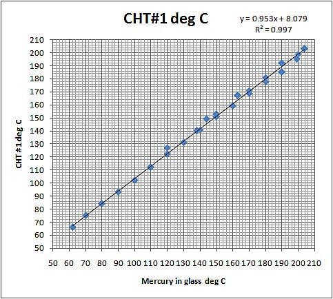
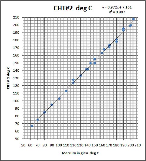
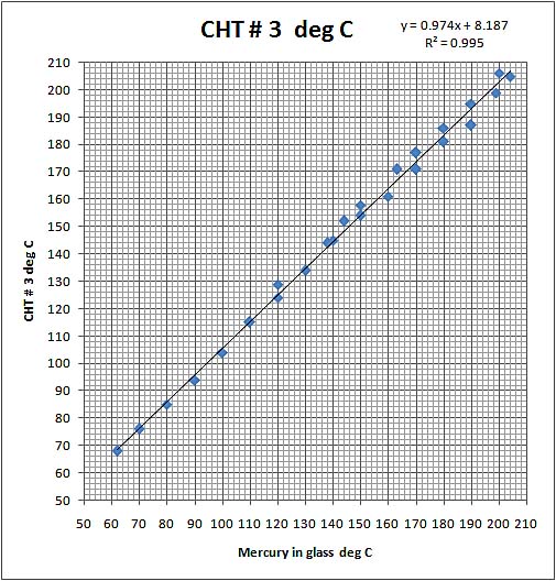
For what it may be worth, here are the results of four CHT calibrations, for K-type thermocouples supplied by Ian Bent, as read by MGL Infinity E-3 gauges, at the end of approximately 3 metre K-type extension leads. The thermocouples had simple crimp-type electrical (plated copper) eyelets which were fastened to the calibration block by 8-32 steel screws. The calibration block was earthed to the system ground, as were the "ground" leads of the E-3 gauges. The E - 3 gauges have cold-junction compensation; the cold junctions were located close to the gauges, i.e. at essentially the same temperature. As you can see, the accuracy was quite good. The graphs are an amalgam of rising and falling temperature data.

-
Thanks, Nev; I understand. However, the whole subject of flight testing of aircraft is very much misunderstood; much of it is about as exciting as watching cement set; but some aspects of it can be very hazardous, and somebody who sets out to venture into the unknowns of a new prototype needs to be (a) a competent pilot, and (b) have sufficient aeronautical engineering knowledge to understand what the aeroplane is trying to tell him, before the situation becomes unrecoverable. So I'm concerned that inexperienced pilots who are really in the stage of "getting the feel" of the aircraft, will ipso facto not be in a position to recognise subtle danger signals. Fortunately, I suspect that most of the test flying is not of that type; but is essentially shaking the weevils out of a newly-built kit aircraft whose basics were sorted out long ago. So it amounts to the equivalent of a production flight test of a newly-manufactured certificated type. For that, one is essentially bedding in the brakes, adjusting "fixed" trim settings, and checking that everything works as it should. That's normally covered by the kit supplier's instructions. You shouldn't need a professional test pilot for that sort of thing. When one is dealing with a new prototype, however, all one really has is the structural design flight and weight/CG envelope - and with amateur-designed aircraft, not even that in most cases. So the test pilot needs some levels of understanding that are outside normal pilot training; also, test pilots in this area have their own jargon; they talk of CG positions as "% MAC" and use such terms as "aperiodic phugoid" (which latter is actually a contradiction of terms, which makes it all the more confusing). But these things are life or death matters, in an unknown prototype; and what I am trying to say, is that unless the pilot has sufficient knowledge to understand precisely what is meant by (for example) an "aperiodic phugoid" and what that implies (negative longitudinal static stability), he should stay away from that activity.
-
I suggest you contact Nick Coulson at CASA and ask for a short list. But see my next post.
-
Nev, if you do not understand what data you should be looking for, you definitely do not know enough to attempt to test fly a new prototype. If you're interested in the subject, download FAA AC 23.8 (I think now at issue c or possibly d). It will give you considerable bed-time reading. A competent test pilot can usually make a fair qualitative assessment in considerably less than one hour's flying. That's cheap insurance, I would have thought. Getting all the numbers takes quite a bit longer; and when you're starting from scratch, there's almost always some development to be done - which means the overall task may take up to around 25 hours for a "simple" aircraft - or possibly more, if some difficult problem shows up.
-
Quite a few good points on this thread. I have a couple of comments, for what they may be worth: Firstly, test flying is a quite different skill set to that of a normally competent aviator. An experienced pilot without actual test flying experience, will normally have experienced many aircraft types - but most of them will be certificated types, which means that whilst they will have different "feel", they will all behave in essentially the same general way. You will no doubt remember the first time you drove a car other than the one you learned to drive on; it felt very different. But when you get to your sixth car, you hardly notice the differences, because under the superficial "feel" they all act very much the same. It's the same with aircraft - provided they are certificated; and this leads people to have an unconscious expectation that all aircraft inherently behave similarly. You do NOT normally find yourself in a car with, for example, negative caster; and to somebody who has never experienced something of that sort, it would come as a very rude surprise. The reason all certificated aircraft behave essentially similarly, is that somebody sweated blood to make them behave that way. They do NOT necessarily do so until their fangs have been drawn. The reason we have operating limits and centre of gravity limits is to define the range of such parameters within which the aircraft does exhibit acceptable behaviour. With a new prototype, especially an amateur-designed one, these limits are not defined, and it is the test pilot's job to determine what the safe operating limits are. Usually, a professionally designed aircraft will have defined structural limits and these will have been worked out for a "structural design" centre of gravity range; but the handling and stability limits are still very much the responsibility of the test pilot. So experienced test pilots usually know a few "tricks" to let them spot marginal or negative longitudinal or directional stability before they allow the aircraft to get into a situation that is unrecoverable. There are other things that need to be approached in small increments, such as the damping of airframe oscillations. Secondly, flight testing is essentially a matter of data collection. The last thing you want is an experienced pilot who will bore a hole in the sky for 45 minutes or so, and then come back, hitch his trousers, spit downwind, and say "She's Beaut!". You need to plan each flight according to the item of data you want; and configure the aircraft to achieve that; then go and perform precisely the planned test and nothing more. In other words, plan the flight and fly the plan. Thirdly, a test pilot must know when to stop. If you lack sufficient knowledge to identify a hazardous condition before it gets dangerous, you will not survive. Flight testing demands precise control of weight and balance. It is not uncommon the weigh the aircraft, with the test crew aboard, before and after a flight. At the very least, the aircraft's empty weight and CG must be determined accurately, at the outset, and each test loading condition must be at a known centre of gravity position. If you do not know how to do that accurately, do not attempt to test fly an aircraft. Flight testing also demands precise control of airspeed - which means that the airspeed system errors need to be determined as early as possible in the test program - just as soon as the engine has been proven to cool adequately, in fact. See CASA AC 21.40 for suitable procedures for ASI system calibration. If you are talking about a kit-built aircraft for which the CG limits and other operating limits are already defined, then the flight testing is essentially equivalent to the "Production flight test" of a certificated aircraft, and its purpose is not to sort out fundamental design issues, but to ensure that the aircraft is in trim, and that everything works properly. That is a task that any relevantly experienced aviator can reasonably tackle. However, the Lancair 235 that I experienced was a kit-built aircraft, and it did have fundamental stability problems; so an LSA kit or a kit based on a certificated aircraft, can be a very different proposition to one that merely meets the "51%" rule.
-
Preventing inflight fires
Dafydd Llewellyn replied to Dafydd Llewellyn's topic in AUS/NZ General Discussion
Dead right; PVC has no place in an aircraft; for a start, the products of combustion are extremely toxic. In regard to the entire subject of aircraft wiring, ALL the answers are in Chapter 11 of FAA AC 43.13-1 ; ALL circuits need to be protected by fuses or circuit breakers and wire ratings, including reduced ratings for bundled wires, are given in that document. -
Zimango motor glider ditching Sunday morning.........
Dafydd Llewellyn replied to a topic in AUS/NZ General Discussion
"Preventing inflight fires" in General Discussion. -
Fire in flight requires (amongst other things) (a) A fuel source and (b) an ignition source. Prevention of fire essentially means keeping these two apart. Let's start with ignition sources: One major potential ignition source is electrical- sparks, arcs, or overheated wiring or components. One good general rule is to locate potential ignition sources separate from, and above, potential fuel sources. So electric circuits should NOT be bundled together with fuel lines, run inside fuel tanks, or located where leaking fuel is likely to dribble on them. FAR 23.863 refers: § 23.863 Flammable fluid fire protection. (a) In each area where flammable fluids or vapors might escape by leakage of a fluid system, there must be means to minimize the probability of ignition of the fluids and vapors, and the resultant hazard if ignition does occur. (b) Compliance with paragraph (a) of this section must be shown by analysis or tests, and the following factors must be considered: (1) Possible sources and paths of fluid leakage, and means of detecting leakage. (2) Flammability characteristics of fluids, including effects of any combustible or absorbing materials. (3) Possible ignition sources, including electrical faults, overheating of equipment, and malfunctioning of protective devices. (4) Means available for controlling or extinguishing a fire, such as stopping flow of fluids, shutting down equipment, fireproof containment, or use of extinguishing agents. (5) Ability of airplane components that are critical to safety of flight to withstand fire and heat. © If action by the flight crew is required to prevent or counteract a fluid fire (e.g. equipment shutdown or actuation of a fire extinguisher), quick acting means must be provided to alert the crew. (d) Each area where flammable fluids or vapors might escape by leakage of a fluid system must be identified and defined. The above rule is not confined to the engine compartment; it applies throughout the aircraft. Be aware of such possibilities as a DC electric motor - e.g. a flap drive motor - being located in the same part of the wing as a fuel line. Incidentally, the ignition of liquid that falls on a hot surface is NOT indicated by the "flash point" of the liquid; a useful rule of thumb in regard to hot surfaces, such as parts of the exhaust system, is whether or not they are hot enough to melt solder; petrol in liquid form needs a bit over 300 C to ignite. Lubricating oil ignites at a considerably lower temperature. Fuel Systems: There is a considerable advantage in the use of an "updraft" carburettor, especially if it is combined by an "up exhaust" engine layout, because this places the hot bits on top and the potential fuel leaks underneath the engine. If the engine layout does not do this inherently, then it is necessary to use splash trays having drain tubes or liquid flow deflectors under carburettor bowls, etc. Also, the use of separate fire sleeving on hoses and lines carrying flammable liquids in the engine compartment has a "hidden benefit" in that it also serves to catch liquids escaping through small cracks in the tube, and thus converts a highly-flammable fuel spray into a dribble at the end of the fire sleeve. Fuel lines that are under pressure - e.g. fuel injector lines - are a particular hazard, especially when the injector nozzles are located high on the engine. The traditional fuel distributor placed on top of an injected engine is an unnecessary hazard, and special care is needed to prevent the injector lines running from it from resonating to any engine vibration frequency. There have been a number of engine fires from this cause, over the years. I have seen EFI systems on recreational aircraft engines that are an accident waiting to happen, from this cause. Fuel lines in engine compartments are required, nowadays, to comply with FAA Technical Standards Order (TSO) C 53 Type D. It is foolish to use less. See, for example, http://www.aircraftspruce.com/catalog/appages/ae466.php
-
Zimango motor glider ditching Sunday morning.........
Dafydd Llewellyn replied to a topic in AUS/NZ General Discussion
See new thread on this issue -
You certainly seem to dislike glider pilots. The Goulburn accident was a winch launch; the collision occurred about 100 feet above the ground - which hardly allowed the launching aircraft time to drift with the cross wind. The aircraft coming in evidently did not see the aircraft leaving the ground because it was "under his nose" and (I can only assume) had been previously hidden behind the row of trees. The winch driver, one might suppose, could have seen the aircraft on final - but he's about a mile away, and the strip, as I recall, has a hump in it - so if the incoming aircraft was making a low approach, it may have been below his line of sight. There are certainly questions that the available data do not answer. But you might, perhaps, at least acknowledge the few facts that are available, rather then shooting from the hip.
-
Zimango motor glider ditching Sunday morning.........
Dafydd Llewellyn replied to a topic in AUS/NZ General Discussion
I'd be most interested to know more about the actual cause of the fire. Engine fires are, fortunately, rare nowadays; that's a result of - amongst other things - much better flexible hoses and a fair bit of attention to the subject in the certification design standards. So when one does occur, the cause is of considerable interest, because it may have a bearing on the design standards. -
Quite true. For what it's worth - a common battery in glider use is the Yuasa REW45-12, which is nominally eight amp-hours capacity. Most of the modern radios use under 300 mA on "receive" and around 2.5 amps on "transmit". Glider pilots do not generally transmit unnecessarily; if you assume the transmit time is 5% of total use, the average current drain would be around 410 mA; so a fully-charged REW45-12 would give about 19.5 hours of use. So if the batteries are fully charged overnight - which is normal gliding club discipline - there would be ample electrical power for a day's flying. Normal usage would use about 40% of the battery's capacity, so it will have a reasonable life under that usage. Because a glider cannot normally "go around", mixed usage on a field is sometimes arranged with the glider strip parallel to the "power" strip, or otherwise segregated; a typical example is Tocumwal. This may extend to the gliders doing opposite-hand circuits to the power aircraft. Gliders usually use a considerably "tighter" circuit pattern than powered aircraft. Tug aircraft usually fly the same circuit pattern as the gliders.
-
Not my experience either; glider radios used (in the 1960s) to be poor, often in the CB band, and gliding ops had some specific assigned frequencies. Most gliding clubs, in the past, operated where carriage and use of radio was not mandatory. However they are now required to use VHF COM and the CTAF frequency, when one is applicable. The Bundaberg club - of which I am a member - has good radio discipline. I'm not sure whether all country clubs will have caught up with this; but it's clearly spelled out in the GFA operations manual.
-
Last time I looked at it (couple of years ago) it had a row of open holes either side of the strip for lighting; you would not want to put a wheel into one of them.
-
Low level flight article in Sport Pilot
Dafydd Llewellyn replied to rdarby's topic in Student Pilot & Further Learning
Try doing VOR intercepts under the hood, just outside Sydney CTZ, in turbulence. -
And this differed from the NSW Wran government's machinations over the Sydney airport at Badgery's Creek, in exactly what fundamental principle? "No man's life, liberty or property is safe whilst the Legislature is in session" (Mark Twain). Now, what was that about democracy? . . .
-
Step 1: Set it up on the ground with the wings laterally level, and verify that the skid ball is centred. If it's not, then the instrument is installed in the panel with a lateral tilt - and you must correct that before trying to use the skid ball to assess whether the aircraft is in lateral trim.
-
Yes, although the choice is a little wider than you may imagine.
-
An AN bolt ceases to be an AN bolt if it's exposed to welding heat; it becomes a piece of Cr-Mo alloy steel whose ultimate tensile strength will be around 80 KSI (instead of 125 KSI minimum). Provided the designer recognised this change in the tensile strength, there's nothing wrong in principle with using an AN bolt as the starting point - tho breathing the cadmium fumes from burning off the cad. plating may not be good for the welder . . . The danger with welding Cr-Mo steels lies mainly in the consequences of fast-cooling them; they must be slow-cooled to avoid embrittlement. They end up in what metallurgists call the "Normalised" condition, if the welder knows what he is about.
-
Propeller breaks at 13,000 feet
Dafydd Llewellyn replied to ayavner's topic in Aircraft Incidents and Accidents
Probably one of those McCauley 2A34 series props; the blades had a counterbore internally from the root end, and the manufacturer used to trim-up their balance by stuffing lead-wool in the counterbore. If any water got in there, that set up a corrosion problem that initiated fatigue failure. Most of those props were withdrawn from service about 20 years ago, because of this. The history of propeller design shows that a lot of variations were tried, but very few have stood the test of time. -
Propeller breaks at 13,000 feet
Dafydd Llewellyn replied to ayavner's topic in Aircraft Incidents and Accidents
You have answered your own question. What suitable attachment spot? -
Propeller breaks at 13,000 feet
Dafydd Llewellyn replied to ayavner's topic in Aircraft Incidents and Accidents
Compliance with a suitable design standard - e.g. FAR Part 35 - or CASR Part 35, for that matter - and the appropriate maintenance requirements - provides adequate safety as far as most people are concerned. Discussing ways to compensate for sub-standard propellers by such measures as ballistic parachutes is about as sensible as debating the merits of various shark repellants, to allow one to swim off Victor Harbour when the Great Whites are about. A sane person who understands the risk, simply avoids the problem. There are at present a considerable number of manufacturers who market composite-bladed propellers. You can count the ones who have put their product through Type certification on the fingers of one hand. Attached is a typical GA propeller Type Certificate Data Sheet. The most interesting part of it is the table of engines for which the propeller has been cleared (in single-engine tractor applications) in regard to vibratory stress (which causes blade fatigue failure in a metal propeller, and can cause delamination in a composite propeller.) It starts about half way down page 6. The "crankshaft damper configuration" refers to the use of tuned pendulous counterweights on the engine crankshaft, to reduce the propeller blade vibratory stress. Now, go see if you can find this sort of information for any composite propeller for recreational aircraft. If you do, please let me know. McCauley2A34 series.pdf McCauley2A34 series.pdf McCauley2A34 series.pdf