RFguy
-
Posts
3,464 -
Joined
-
Last visited
-
Days Won
47
Content Type
Profiles
Forums
Gallery
Downloads
Blogs
Events
Store
Aircraft
Resources
Tutorials
Articles
Classifieds
Movies
Books
Community Map
Quizzes
Videos Directory
Everything posted by RFguy
-
Bydanjohnson Rumours About A New Pipestrel Trainer
RFguy replied to mnewbery's topic in Aircraft General Discussion
"It's a little like learning to fly within RAA because "it's cheaper - advice given time and time again on this site, but by the time the student has to learn to fly the less-developed Rec aircraft the extra hours load up, and then there are the extra hours learning GA system and procedures to the point where without some luck it's cheaper to do all the training in GA to PPL." That is not true. Little difference between the Brumby and Jab I learned in and the 'big ' Piper I now fly. I did have an instructor that taught like it was GA.... So I had zero extra to learn to fly the bigger airplane in complex situations..... The Instructor makes alot of difference. I do know RA people who I think fly and do stuff like they got their licenses out of a corn flakes packet. But I also have seen GA people do some poor airman's ship things. -
go with a big bore 912(low compression) and a afterthought turbocharger. Or if you are scared of heights and heat , just a 912ULS with big bore kit. Jab Gen4 is OK, also , but not really cheaper than a rotax per hour. so you might as well buy a medium lifed rotax if you have the cash. If you have not much cash, you can get a 400-800 hour Gen2/3 Jabiru for peanuts and rebuild it to new for 5k. BUT ! the aircraft nose weight requirement will drives things, also. Lycoming O-235 would be my first choice if nose weight was required.
-
Light aircraft crash near Palgrave, Qld. 19/10/23
RFguy replied to dlegg's topic in Aircraft Incidents and Accidents
Enter the term : AutoIgnition temperature (AIT) (not to be confused with flashpoint) ... OIl has a lower AIT than gasoline. Doing some reading, the autoignition temperature is probabalistic- to get reliable ignition, for gasoline LIQUID , you must be miles over, like 2x the AIT to get reliable combustion - around 580C for gasoline. 450C for engine oil approx. (ignition is where the rate of gain of heat is positive) The AIT for varies for varying surface area to volume ratio is high (IE vapourized), amount of oxygen, pressure, turbulence etc etc etc . Someone here will know this stuff better than I . Please chime in. in my experience, hard to get a fire if a little fuel drips on a exhaust or manifold,With oil, I've only had lots of smoke (vehicles). But, it's probabalistic, get enough action and it will ignite if above some temperature. The AIT definition is temperature that ignition occurs at normal atmosphere and the state for that material in that atmosphere (ie liquid for gasoline, oil ) -
Light aircraft crash near Palgrave, Qld. 19/10/23
RFguy replied to dlegg's topic in Aircraft Incidents and Accidents
excellent comment ! OK there it is : dont forget to re-calc /measure the W&B https://www.firefree.com/fire-retardant-fire-resistant-paint-products/ff88-intumescent-coating.php https://www.firedefender.com.au/pdf/TECHNICAL-DATA-SHEET-AU-FINAL.pdf A couple of things- the fibreglass going above its glass temperature will quickly lose its shape/strength. The fire guard stuff might be useful to prevent the fibreglass itself catching fire. Others will no doubt have some experience here. -
Light aircraft crash near Palgrave, Qld. 19/10/23
RFguy replied to dlegg's topic in Aircraft Incidents and Accidents
MarkDunstone in conversation made a good point that high pressure leaks may well vapourize effectively the fluid into a nice combustable mist... Fire sleeve whilst becoming soaked, would contain the spray ultimately turning it into a drop/liquid, rather than an aerosol. -
Light aircraft crash near Palgrave, Qld. 19/10/23
RFguy replied to dlegg's topic in Aircraft Incidents and Accidents
yeah , like I said in my expose' - ".. unless a hose to and from the oil cooler failed, that would end up on the muffler. " Those are barbed fittings and must be clamped correctly. Oil filter could have failed, also, there have been a few oil filters split / come off..... -
SP500 OK. wiring varies ! "So do you think the damage might already be done with the voltages being so high?" ---anyone's guess. See how you go. Usually, protection devices clip the peaks, but if the battery gets that high, the peak limiting devices are usually cooked and may require replacement (if it has any) Get it all wired up. See how it goes. if it all works, then good.
-
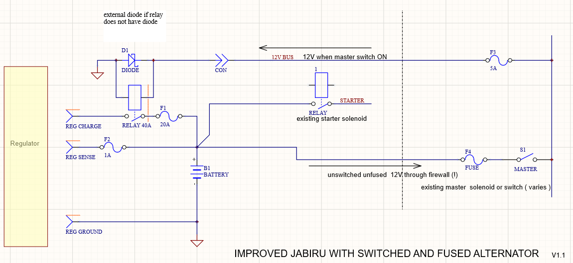
Hi Jenny. WHat's the aircraft type and SN ? Yeah if you do " improved jabiru with switched and fuses alternator" circuit that will go a long way to removing the chance that that is a problem. (Ideally you do method 1 or method 2 diagrams but this is a fair bit more work but ensures you can disconnect the battery) When the voltage goes sky-high- the device called a crowbar in the Jabiru bus wiring may begin to 'arcing over' and causes ALOT of noise. ALSO many electrical devices will have their own 'crowbar' - a type of high voltage transient suppressor - will begin to conduct to try and clip off the high voltage peaks and make alot of noise.
-
Light aircraft crash near Palgrave, Qld. 19/10/23
RFguy replied to dlegg's topic in Aircraft Incidents and Accidents
An in flight fire... putting aside eletricals , and looking at a fluid induced fire : At my last annual on the Piper, all fluid hoses under the cowling got replaced. Cost a bit. They were pretty old , well outside the hose manufacturer limit of 8 years, and various other requirements . They bent OK, so, OK. I'm OK with the replacement requirement - an oil or fuel hose leak under pressure would be bad . Unlike the rotax setup, which weaves all around the cowling , The fuel line run in a Jabiru is short from firewall to fuel pump and carb direct. In a Jabiru, an overflowing Bing carby cannot easily end up on the exhaust manifold OR muffler ... it is behind the exhaust muffler . A leaking gasket on the fuel pump might be possible, but it would likely be drops. THose fuel lines are only a few psi, I would be surprised if the hose came off with or without a worm-band clamp. Oil leaks- any engine oil leak from the block and push rod tubes is going to be SLOW. drops.... unless a hose to and from the oil cooler failed, that would end up on the muffler. The Rotax requirement of 5 year replacement on hoses also is a bit too much of an B-S overstretch by the Rotax I think, There isnt much pressure in those hoses - the oil is low pressure or under vaccuum, and the water, well if you lose water, that's your own problem. Fuel - that's the $64 question- a fuel hose leak is bad. A few are probably improperly terminated hoses (band clamp in the wrong place etc ). Fire sleeve is good but might mask leaks but will contain a serious leaf and provides additional protection . Hence a good reason to go for high quality hose. A hose manufacturer that stands to cop reputational loss if you have a problem . I would some hose failures in LSA are related to friction between the hose and something else. My Jabiru had a chafed fuel line hose. I'd be much more concerned about fuel hoses in the rotax (long and many) , and I'd be more concerned about where the overflow from the carbys are (rotax) - right over the exhaust manifold. So take care with that... The Lyco has steel braided hoses everywhere. A good reason.... RAAus are going to have to expend money to get to the bottom of this. In flight with engine spluttering ( as reported above) could be anything, but suggests to me fuel starvation and a fuel fire AT A COMPLETE GUESS. -
Light aircraft crash near Palgrave, Qld. 19/10/23
RFguy replied to dlegg's topic in Aircraft Incidents and Accidents
With refernce to the post about the battery fire of the tasmanian fire, : Read what the ATSB wrote about the TASMANIAN accident and as usual t they've made mistakes and wild assumptions that are not necessarily correct..(about battery chemistry) .. I have told them.... Lithium Iin (Polymer) batteries associated generally with scooter fires etc are different chemistry to the Lithium Iron Phospate. This was a Lithium Phosphate battery, most likely, and while they can experience thermal runaway, it's hard to acheive..... It would have to depend on the ratio of charge input to capacity .... The weight of the battery would be able to tell us that. Chargers and regulators (for any chemstry - but particular Lithium chemistries ) should probably have battery temperature cutoff for disconnect of charge or discharge. -
Light aircraft crash near Palgrave, Qld. 19/10/23
RFguy replied to dlegg's topic in Aircraft Incidents and Accidents
I wonder if my concerns about the way Jabiru aircraft are wired is any contribution to the (post?) accident fire. -
NO ground 'circuit'. Ground location - yes. But regulator CANNOT go to the busy ground say on the firewall that a bunch of things front side and back get connected to. The reason for connecting the regulator direct to battery ground (or - the engine block is pretty well battery ground because of the 50mm2 cable to the battery negative) , is that high pulsing current from the regulator needs NOT to crosstalk with other signals. If the alternator regulator negative goes to some 'ground bus' then that whole ground bus will be noisy unless there is another (short) 50mm2 cable to the bat negative. it is no longer ground if you connect the noisy charging current into it. ground is supposed to be quiet.
-
so in that case, needs a shaft through the firewall to the battery isolator location. Yes, I do like that !
-
Nev, pls expain the 'crash bar' comment ? Do you mean some sort of method to short the bus and blow the battery fuse ?
-
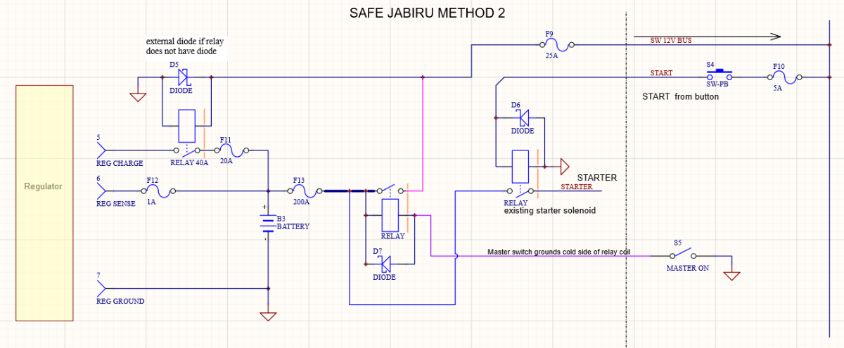
SAFE JABIRU - WITH BATTERY ISOLATION - METHOD 2 - ROUTING STARTER CURRENT AROUND MAIN ISOLATOR (AND THUS CAN USE SAME 40 AMPS RELAY AS ALTERNATOR )

-
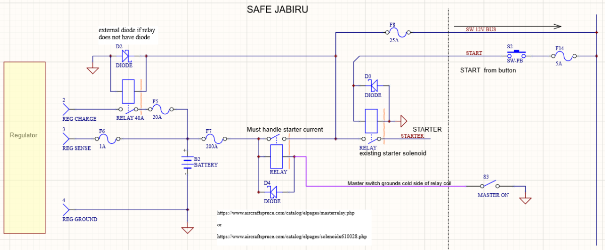
SAFE JABIRU - WITH BATTERY ISOLATION - METHOD 1 - ROUTING STARTER CURRENT THROUGH MAIN BATTERY ISOLATOR \
-
V1.1
-
-
Good. 5A fuse for the sense wire OK. The wire will pass 5A and blow the fuse if there is a fault. (remember- idea is that fuse blows before wire melts) In your photo, the starter V+ goes to the starter solenoid ..... I see a smaller red wire going to the battery V+ terminal to a connector off photo - I gather this is the regulator charge output (check). this needs to have a 20A fuse in it so that if the regulator fails it doesnt cause a fire. There needs to be THE alternator charger relay that we discussed in series with this 20A fuse. The alternator relay can have the negative of the coil to ground (anywhere) and the positive of the relay coil should go back through the firewall to your MASTER 12V bus. That is the minimum for modifications And regulator sense wire to battery termal. If you want to go further, you can see that there are UNFUSED battery white wires going through the firewall. This is bad in an crash- the battery master relay needs to be IN the engine bay and connected to the master switch. so that unfused and unswitched battery + does NOT go through the firewall ..... There is a master relay behind the instrument panel, that relay needs to be moved next to the battery and via a good sized fuse probably 30A is enough for a Jabiru.
-
Jabiru company aircraft wiring is... questionable. Battery sense should ALWAYS go to the battery (via small fuse) NO MATTER WHAT. anyone who wants an argument, put $10,000 on the table and let's have a bet. Comon, I'll see you in court. Battery charge should go to the battery to remove alternator 'noise' components from the wiring harness. If the battery charge wire goes to the harness/master, then high frequnecy battery charge current 'noise' will fill and pollute the 12V bus . Battery charge must go via a fuse (20A in this case) AND ideally, via an isolation relay that is actuated from the master 12V bus. Battery negative SHOULD go to the negative battery terminal BUT engine block is good enough because starter cable size, direct to battery negative, is usually sufficiently sized to not have any voltage -current noise. Jabiru factory wiring practice I beleive, may be responsible for Jabiru airframe fires. IE the need of a master battery contactor - because std Jab wiring puts UNFUSED battery B+ through the firewall. Where as good practice, and safe practice, and certainly all part91 cert aircraft, the battery is isolated at the battery via a contactor/relay which is turned on and off via a battery master switch. This has been well covered by me here several times.
-
Hi Jenny well, if the 'avionics guy' didnt connect the battery sense wire, he either was having a bad day, or needs to be sued, or the wire 'came off'. So, I am sure there is more to this story. ANyway, get what I suggested done. If the headlamp relay doesnt have a 'flyback/reverse' diode across the coil, ensure that one gets put on. No-----, if you fly with high voltage like that (The TRUE peak voltage is much higher than indicated) you'll damage everything connected to the 12V bus..... If not damaged now, you will reduce the life and things will die for no reason prematurely, even after it is all fixed up.... Use something like a : - they have the diode in them. NARVA 68032 or 68032BL NOTE THAT THESE UNLESS MOST RELAYS WILL HAVE + AND - ON COIL . - to ground, + to 12V bus so relay turns on when master on Repco Australia | Auto Parts Store - Aftermarket Car Parts WWW.REPCO.COM.AU Narva | 12V 40A NORMALLY OPEN 5 PIN RELAY WITH DIODE (BLISTER PACK OF 1) WWW.NARVA.COM.AU Narva relays are manufactured to exacting original equipment standards under the control of ISO9001. or Narva | 12V 40A NORMALLY OPEN 5 PIN RELAY WITH DIODE WWW.NARVA.COM.AU Narva relays are manufactured to exacting original equipment standards under the control of ISO9001. NARVA 68032 or 68032BL
-
yes indeed, the regulator has no voltage sense so it just thinks the battery is flat all the time voltage sense wire must be connected. WHo did this work prior to you ???? Needs all the wires for the regulator connected. Jabiru's wiring is a bit F-ed up anyway, but it can be acceptable. DO NOT fly or run it over 1500 RPM with the regulator like that- you will damage ALL of your electrical systems and electronic instruments.... Regulator negative should go to the engine block which has a really good solid negative wire connection to the battery via the starter cables. Regulator sense wire (usually yellow) needs to go to the battery via a 1 amp blade fuse. Regulator charge output needs to go direct to the battery via a 20A blade fuse . There will be a tiny bit of current always drawn so it might flatten the battery over a couple of months. IDEALLY an extra relay (small cube headlamp relay will do it) is required from the master , the relay goes in series with the alternator charge output so when the master turns off, the regulator charge output is disconnected from the battery. and....Transient voltage suppressors or diodes need to be across the main bus to avoid the master relay back EMF damaging radios and electronics, as it does....
-
how good is the ADSB coverage in the region at ground level- is this the termination of flight, or just the ADSB coverage limitation ? glen
-
Help with OzRunways - playing with it.
RFguy replied to flying dog's topic in Student Pilot & Further Learning
My Samsung A8 tablet internal GPS works fine, providing the orientation is in portrait mode up. (this is important !!!!). do not need internet en route. allow 10 minutes to get GPS though. -
Looks fantastic. I did 'airwork'. practiced flapless approaches, glides etc. It took 4 goes for me to make the glide approach work.... in nil wind. tut. tut. needed the practice after flying many 400nm A to B flights.... I even got carb ice ! (during startup/ runups) .