
Head in the clouds
-
Posts
1,842 -
Joined
-
Last visited
-
Days Won
42
Content Type
Profiles
Forums
Gallery
Downloads
Blogs
Events
Store
Aircraft
Resources
Tutorials
Articles
Classifieds
Movies
Books
Community Map
Quizzes
Videos Directory
Everything posted by Head in the clouds
-
 I don't understand how this program can work. Since the most 'junior' operations QANTAS operate is their regional Qantaslink service, and that is a full RPT operation, every pilot with hands on controls has to have an ATPL. Unless Regs have changed you need 1500hrs command time to qualify to sit the ATPL exams, so how can they have FOs with just a shiny new CPL flying RPT ops?
 -
A riveting weekend
Head in the clouds replied to planet47's topic in Aircraft Building and Design Discussion
And also not a tricycle where you get out and it becomes a fall-on-its-ass ... -
Yes ... but wasn't it also the first pure jet cropduster? Might have been ugly but probably quite practical I'd think, huge hoppers in the right place, high tail and all that. Lots of wing area, structurally simple. And let's be fair - the Russians have built far uglier aircraft than that one ;-)
-
I can't recall what it's called but it's a Russian cropduster I think.
-
DooMaw - building a STOL
Head in the clouds replied to Head in the clouds's topic in Aircraft Building and Design Discussion
Hi ClintonB, thanks for your feedback! Yes, everything I've read suggests that the main reasons top coatings crack is due to lack of sufficient plasticisers (given that it's applied to a flexible fabric, rather than a steel auto body panel or house exterior, for examples). As I understand it from their documentation, the Stewart System's own topcoat contains plasticisers that, once cured, leave it looking 'glossy, almost wet' on the surface. A couple of people have suggested that's right. I guess it's everyone's choice of which topcoat to use, because the Stewart filler coat apparently provides all the fabric sealing/filling required, as well as the most important UV protection. After that they offer a topcoat that isn't cheap at US$338/gallon but those who have used it seem to recommend it. On the other hand polyurethane topcoats are about 1/3 their price and are known to be flexible (one can add more plasticiser if you like) and PU is very 'tough' and high gloss as a surface coating. So - thanks for all your contributions and I'm very much still open to more info please folks ... -
DooMaw - building a STOL
Head in the clouds replied to Head in the clouds's topic in Aircraft Building and Design Discussion
Thanks for all the info folks. OK, great to have some feedback about the Stewart system, really appreciated. Also, what you say about the size of the oil cooler is taken on board, I have a friend who has lots of experience with this and he said he has to tape over most of his oil cooler in winter and about half of it in summer. But then he's in Tassie these days ... So I'm quite happy to have a large cooler, can always restrict airflow to it but it may well come in handy on a 40+ degree day outback. Good point about the reverse airflow Oscar, thanks, I hadn't actually thought that through but it just didn't 'seem' right where I had it at first. Thanks for the info about the smaller elbow Bluead, I did think this one was rather bulky but in the new position it fits rather well to run the oil hose between the coolant hoses and the pushrod tubes, so it'll do well at this stage. -
DooMaw - building a STOL
Head in the clouds replied to Head in the clouds's topic in Aircraft Building and Design Discussion
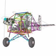
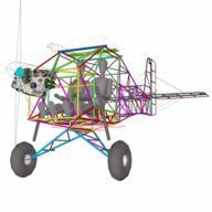
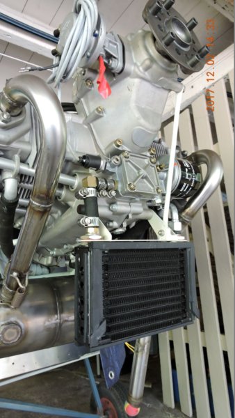
2nd December 2017 Real work is getting in the way again, so progress has been a bit slow. I built the oil cooler mounting bracket, fabricated and welded up out of aly angle. I loosely copied the oil cooler/coolant radiator setup of the Foxbat but didn't end up liking the cramped location of the oil cooler tight under the spinner, where it has to be to allow enough room for the coolant radiator below it. Then I saw in the Rotax installation manual that the oil cooler is required to be below the oil pump, which isn't the case for the Foxbat but they seem to get away with it. I also didn't like the inlet/outlet being at the bottom of the oil cooler, it seems to me that there'd be a likelihood that the oil could just enter and exit in the bottom part of the cooler and it might never be filled with oil, especially since it is on the suction side of the oil circuit. Anyway, I threw out that mounting hardware and started again. This time I have plenty of space to play with, the oil cooler is up the right way, the hoses aren't perilously close to the exhaust pipes, and the coolant radiator will be mounted vertically into the port side of the cowling. That'll appear a little unconventional but makes a lot of sense in terms of keeping the coolant hoses short and away from the exhaust headers, and the radiator will still be in good airflow whether flown with the engine cowling on or off. Now it's time to get what will hopefully be the last hardware orders in from the US, so I'm having to spend time going carefully over the whole project to determine every missing bolt, nut, clevis pin, bearing and all the rest of it. By the way, does anyone reading this have any experience with the water-based Stewart covering system? Until yesterday I had every intention of, and was looking forward to using Oratex, until I calculated the amount of fabric I need and priced it up along with the special tools required. It worked out to be more than triple the price of conventional dacron covering and coatings, so although I haven't completely given up the idea I'm also investigating other options - hence the question about the Stewart system which avoids the use of flammable coatings and dangerous goods freight costs. Pics of the oil cooler setup - 11 hours for the log making a total of 1787 so far.
-
Kickstart the Bugatti "Blue Dream"
Head in the clouds replied to Head in the clouds's topic in AUS/NZ General Discussion
Thanks. Yup, remember it now. Strange though, whilst the incident report refers to the right rear prop reversing pitch, many of the pictures of the XF-11 show it with only one prop per engine. Perhaps those pics are mis-titled and the tested XR-11 didn't use the twin axial props? -
Kickstart the Bugatti "Blue Dream"
Head in the clouds replied to Head in the clouds's topic in AUS/NZ General Discussion
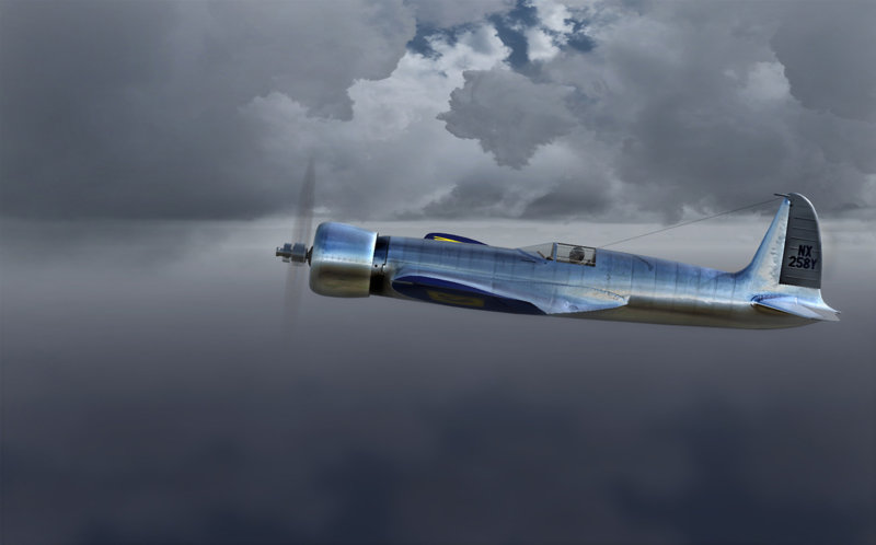
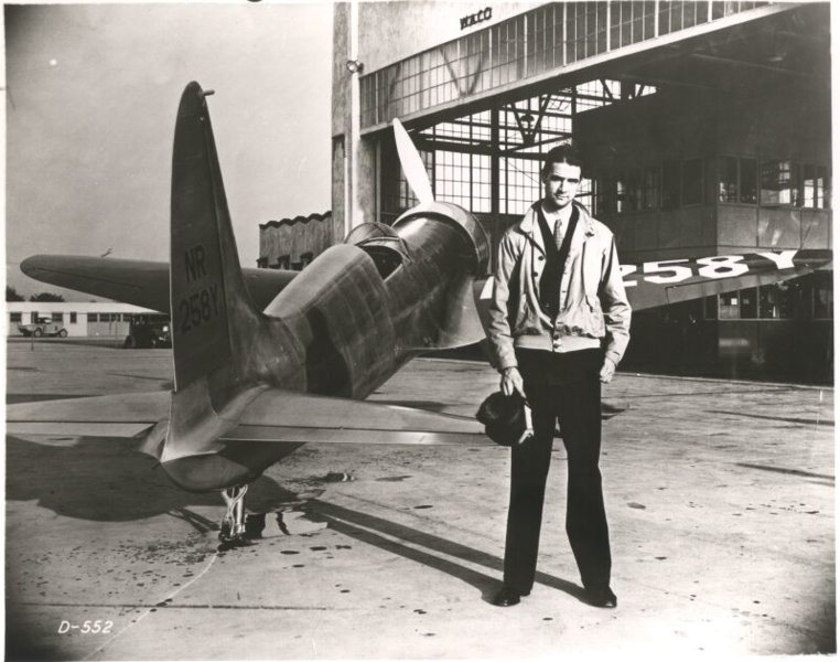
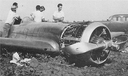
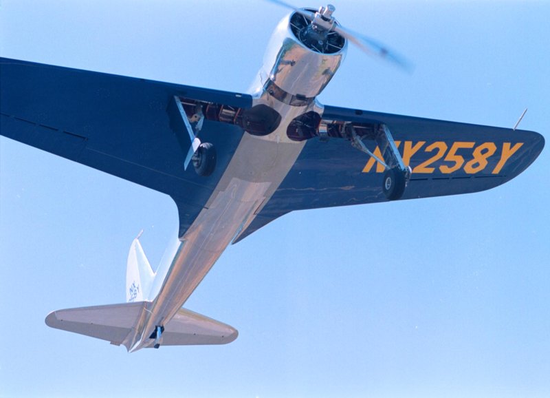
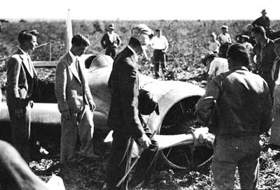
OK, you've got me again turbo. I've been trying to recall this one but I only know of the Hughes H-1 racer that he did crash and I think he maybe clipped a building before putting it down in a ... was it a beetroot paddock? Anyway, that one wasn't contra-rotating or anything particularly complex about the mechanicals, just a sleek airframe and big horses. Planform does have some loose similarities to the Bugatti. Were you referring to a different one?
-
Kickstart the Bugatti "Blue Dream"
Head in the clouds replied to Head in the clouds's topic in AUS/NZ General Discussion
For those with an interest, Le Reve Bleu team have now published their Bugatti 100P Crash Investigation which collates the information from all sources, including the ATSB final report. Bugatti 100P Crash Investigation -
Kickstart the Bugatti "Blue Dream"
Head in the clouds replied to Head in the clouds's topic in AUS/NZ General Discussion
deleted...Mod -
Kickstart the Bugatti "Blue Dream"
Head in the clouds replied to Head in the clouds's topic in AUS/NZ General Discussion
winsor, you're way out of line! I spent many happy times on the phone with Scotty and exchanged dozens of emails, and was also in regular contact with other workers and suppliers to the project, so I can reasonably well claim to know what was going on. I was also working with Scotty to bring the aircraft on a tour to Australia once initial flight testing was completed and negotiations with a major Australian international airline for sponsorship to achieve that had been progressing well. Please provide a link to ANY legitimate report, let alone THE accident report which suggests that there was an instability problem. There is NO SUCH THING as far as I am aware - so I would be very intrigued to learn where you came across that idea. Having said that, the design was never intended to be anything more than neutrally stable - it was intended to be a racing plane, after all. In those days (late 1930s) racing planes weren't only designed for straight-line speed tests in two directions (like the earlier Gee Bee, for example), they also had to race around closed circuits like pylon racers, so positive pitch stability was not a design consideration, otherwise their turning radius would be too wide and therefore they'd lose time in the turns. The 100P was assessed to be not only capable, but intended, for sustained 9G turning efficiently i.e without excessively losing speed - and you won't achieve that with a Sunday driver's super-stable Cessna type I'm afraid. If that offends your sensibilities of what's flyable or not, well that's your problem. Louis de Monge was a specialist designer of that era of manoeuvrable aircraft - he designed it by the way, not Bugatti, so your earlier comment about Bugatti wanting something 'pretty' is another nonsense. Let alone that, I guess you're also not aware that Scotty was a career USAF pilot with full test-pilot training and considerable experience actually in command as a test-pilot? So far, you're right in just one thing, it wasn't engine failure that caused the crash, it was a clutch failure. Why don't you read the real accident report? I provided a link to it above. And - as far as another of your nonsense comments "And note... the only almost scale RC Bugatti was extremely unstable in flight and crash landed." - is concerned, I say - RUBBISH! Get your facts right please. I posted two videos above which show as close to scale models as can be achieved given the limited surviving drawings and reverse engineering (one was directly sponsored by HobbyKing who wouldn't be involved in any situation that might lead them into disrepute), and they are just two of dozens that you can find if you spend five minutes googling instead of sniping at people who are out there doing things. -
Kickstart the Bugatti "Blue Dream"
Head in the clouds replied to Head in the clouds's topic in AUS/NZ General Discussion
That's a rather cynical outlook winsor. There have been numerous models built and flown which demonstrate that whilst it's clearly not for a low-hours pilot, it flies very well and based on the power-to-weight ratio it's exceptionally efficient and therefore very fast. The only real issue has to do with the main gear being too far aft in the original and true-scale models, making the take-off and landings prone to nosing-over. In that regard Scotty had taken a little 'licence' and moved it forward just enough to get away with it with careful handling. Anyway, I know that I, and a number of other forumites here, are very proud to have been sponsors of the Blue Dream project and if you consider it to have been a 'cartoon aircraft', well we all have different perspectives on things I guess. From 4:40 ...
-
Kickstart the Bugatti "Blue Dream"
Head in the clouds replied to Head in the clouds's topic in AUS/NZ General Discussion
The final report from the NTSB has been released though for some reason I can't open the report but here is a link to the Docket containing the various documents. The findings are summarised on the Bugatti 100P FB page. It seems there was a failure of the front engine clutch system causing a lack of power to the front propeller. This was apparently verified by the footage from one of the onboard GoPro cameras where the engine revs were seen to be increasing but the prop revs were decreasing. It appears that Scotty was aware of the problem and was manoeuvring to try and clear the boundary fence and put it down in the adjacent paddock but stall/spun in the attempt. All very sad. -
Don't shoot the messenger ... The first time I flew to the far north was 1989, two of us in a Drifter, no ground crew. Left in May, returned in September. As far as I recall the trip was Kooralbyn - Dalby - Roma - Augathella - Blackall - Barcaldine - Longreach - Lorraine Station - Cloncurry - Mt Isa - Gunpowder - Burke & Wills R'house - Gregory Downs - Normanton - Burketown - Doomadgee - Lawn Hill ... from there we went via Hells Gate and Nathan River - Borrololla - Ngukurr - Mataranka - Curtin Airbase - Pine Creek - Darwin (MKT) and then return via stops in Kakadu - Arnhemland (various) - Tennant Ck - Barkly Homestead - Camooweal - Lawn Hill - Cloncurry - Lorraine Station - Emerald - Rolleston - Taroom - Miles - Kooralbyn The point of writing all that was more than just a trip down memory lane, though a good one of that it was anyway ..., but 1989 was a La Nina year, just like this one is looking like being, and the first half of our trip was a comedy of getting bogged every time we landed off 'made' surfaces, even on the grass alongside runways, and bogged to the boomtube wherever there was blacksoil which is most of central and north Qld as far as the Gulf. And - I had big golf buggy wheels on! It was fun since we had the time for it not to be an issue but had we known how wet it would still be, we might have left a month later. Just something to keep in mind. Once you're north of the Gulf and hit the clay, redsoil, sandy or rocky ground it's not a problem, but a hint of moisture on blacksoil areas and you're done for, so take a folding shovel ...
-
Hi BP, wish my DooMaw would be finished by then because I would have been joining your group for sure. Anyway ... next time. Having done that trip and other similar ones to the north, by Drifter, Cessna and helicopters on many an occasion, a couple of pointers that you might find useful - Keep in mind that planning going up or back along the coast has several issues, the main ones being CTA and the risk of weather coming in from the sea and pushing you up against the Divide, or weather flowing off the land and pushing you offshore. Your chosen time of year does reduce the weather issues a fair bit though. A support vehicle(s) can be mighty helpful but also a PITA when they can't keep up or access where you want to go. The cost of running the support vehicle, in my mind, is better spent getting locals to help along the way instead. The main thing I noted from your OP was your intention to fly in the mornings and evenings. IMHO that's a really bad idea. From experience I'd suggest you get all your day's flying done as early as possible in the morning. Fuel up the day before, get up and breakfasted in the dark in the morning and be airborne at very first light. That way you can have five hours' flying done in the smooth air before 10am and before headwinds pick up - they're always headwinds, it doesn't matter which way you're travelling ... Apart from the better climate for flying there are a number of other reasons to do it that way. You get your plane tied down early and are more likely to find people at airports who might help with your transport/fuelling needs, also sometimes hangar space, and certainly local knowledge. Then you have the rest of the day to explore the local area before returning to your hotel and be able to relax instead of fuelling and tie-down, transport to town, and all that at last light. And - most importantly - when something goes wrong, as it often does, if there's a mishap, bad weather, get lost etc ... you have lots of daylight to sort it out, whereas if something goes wrong during the evening flying leg of your day, it'll be a case of waiting until morning to sort it out, and if someone was injured that could make the difference between survival or not.
-
This is going to end well...
Head in the clouds replied to Marty_d's topic in AUS/NZ General Discussion
My next door neighbour is a man called Mick Van Moorsel, he's quite a famous stuntman - recently returned from LA after taking out the 'world's best' award. Among his claims to fame are providing many of the vehicles used for the Mad Max films as well as performing a lot of those stunts. Last year he was asked to be the 'stunt vehicle supervisor' for Eddie Braun's re-creation of Evel Knievel's 1974 attempt to jump the Grand Canyon in a steam-rocket powered 'skycycle' which was virtually identical to the one Knievel used in his failed attempt. This time they made it ... those steam rockets are quite something, tiny, but 10,000hp reaching about 430mph (650km/hr) in 3.9 seconds during a 427m parabolic flight, quite a ride! Gold Coast Bulletin report - Gold Coast stuntman helps get steam rocket over Snake River Canyon This is a better video of it - -
Groppotrail - Folding Wings
Head in the clouds replied to Super Cub's topic in Aircraft General Discussion
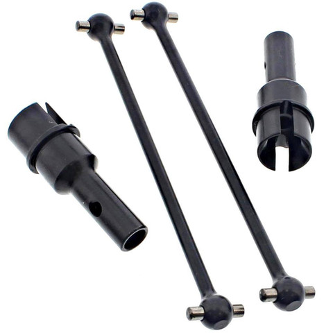
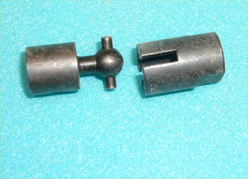
Hi Pylon, Yes I think you mentioned the diaphragms/bolt-in-tension thing. As you say, it's probably well strong enough though it doesn't look ideal. The bolt-in-tension aspect is fine, in fact bolts seem to be used in shear mostly on aircraft and similar structures, but they actually have a higher rating in tension than in shear. These days my day job is in structural steel and whenever lifting lugs are attached to anything the bolts are always arranged in tension, so I'd say that's probably the best way to go about it even if it doesn't 'feel' quite right. The benefit of using bolts in shear for aeroplane struts is that it provides a good start for adjusting/setting dihedral and other wing rigging. Down the track I'd expect that Groppo might develop machined parts for their top strut fitting, rather than fabricating them, for better looks and structural consistency if nothing else, and especially if it makes the customers happy ... My DooMaw has wings that fold similarly, except they hinge at the rear spar for a less tall folded package (though it has the penalty of being longer), so I also needed a 'wrist' mechanism at the top of the strut. I machined mine from 6061T6 billet. As a one-off set it was quite a time-consuming business but for a production aircraft kit using a multi-axis CNC milling machine it would probably be a lot quicker than fabricating them. Pic of my strut fittings, also the second and third pics show a 'dogbone' arrangement, one of many ways to have auto-connect controls -
-
Groppotrail - Folding Wings
Head in the clouds replied to Super Cub's topic in Aircraft General Discussion
With respect I think you miss the point. There are numerous means of having auto-connect/disconnect controls which cannot, under any normal circumstances, come undone. They don't employ loose nuts or whatever you have in mind. For one easily researched example have a look at the paddle system that is used for Sonex to fold their wings. My own project uses a 'dog-bone and socket' system (imagine a tube with a slot cut into the end of it and the mating half is a rod with a cross-pin), controls lightly sprung to centre when disconnected they must engage when the wings are unfolded and there is nothing to come loose, in fact all parts on each side are welded together ... Then there's the type of articulated system used for aileron connections when, for example, the wings of a Kitfox/Skyfox are folded, they just accommodate the geometric change as the wings fold, they are never disconnected or re-connected, they always stay connected whether the wings are folded or not. Then there's the Pylon 500 hinge mechanism which allows the horizontal stabilisers/elevators to be folded up when the wings are folded, making a still smaller package, and the controls always remain connected - it's just simple geometry and a clever idea, thanks again Pylon!. As far as removing/replacing duals on helicopters is concerned, I was a career comm heli operator and did get my own Approvals to remove/install them on several types, but that has nothing to do with it. Removing/fitting a set of duals doesn't have anywhere near the risk we're talking about here. Duals are just that ... Duals ... the primary controls don't get interfered with at all. In fact there's more risk with the common practice of turning the H369/MD369 pedals back onto each other to lock the pedals (due to the risk of not properly engaging them again, than there is with adding/removing duals. You may not be aware of the not-inconsiderable number of fatal incidents, in Australia and Globally, immediately following re-rigging of sport aircraft types from a folded/trailerable condition? The problem is that in some cases it's not easy to determine whether connections have actually been correctly made prior to flight loads being applied, and by then it's already too late. 'Auto-connect or no folding' is already well along the way into regulation in both Europe and USA, and has been since the Ark for Type-Certified, so if you're planning to distribute these types I'd think it's something you'd do well to look at from a litigation-avoidance aspect if nothing else. -
Groppotrail - Folding Wings
Head in the clouds replied to Super Cub's topic in Aircraft General Discussion
The wing-folding is certainly nice enough though it results in a very high package for trailering, if that is part of anyone's plan, but the control connections really need a complete re-design. For the next little while owners might be able to get away with connecting and disconnecting primary controls for wing-folding but it won't be long before it requires an L2 at least, or quite probably an L4, to sign it off each time someone unfolds the wings and re-connects the controls, unless that person was the original kit builder ... which doesn't bode well for onselling. It's not that difficult to design controls that auto-disconnect and auto-connect when the wings are folded. There are plenty of designs that do it with various different means employed. -
More of Jean-Baptiste Chandelier's magic amid stunning scenery in Portugal, France, Brazil and South Africa -
- 1 reply
-
- 6
-

-

-

-
Theoretical speed from prop pitch?
Head in the clouds replied to Enigma's topic in Engines and Props
Yes, your basic calcs are on the right lines. It is a screw working its way through the air but fallowdeer is also correct, the lifting aspect of the blades is a more efficient way of doing the same thing, than using flat (i.e non airfoil shaped) paddle blades. IIRC, as a rule of thumb, and since air is compressible, you might allow 20% for slip, more in draggy situations, and less for clean airframes. Any amount of pitch is possible but what happens is that with very high pitch angles, during take-off the airscrew blades will remain fully stalled until considerable airspeed is achieved. That means lots of horsepower to even be able to get airborne, and then remaining in ground effect to build airspeed until the relative airflow angle becomes sufficient to unstall the blades. That requirement for high horsepower is what might be expected anyway for a 400mph airplane, but careful piloting is critical, any attempt to climb while the blades are stalled and producing heaps of drag can, and have been (in racing types of planes particularly), catastrophic. That is where variable pitch propellers come into their own ... Welcome to the forum, we need more Enigma, or should that be Enigmas ... or is it Enigmata? Damn ... you've been here five minutes and created an enigma already ... -
DooMaw - building a STOL
Head in the clouds replied to Head in the clouds's topic in Aircraft Building and Design Discussion
Hi Mark, thanks for the very kind words! What happened was that when I built the exhaust for AussieMozzie, the muffler was hard-mounted to the fuselage and set vertical so I had to move two of the muffler inlet sockets to the other end, so all four sockets were at one end of the muffler, the opposite end from the tailpipe. Then I made up the pipes from the heads to the muffler before realising that wouldn't work because the engine could move on its rubber mounts but the muffler couldn't ... so ... I cut each of the pipes and added another set of the flared cups and balls and retaining springs into each pipe i.e. each pipe from the cylinder head to the muffler was in two pieces instead of one, so that extra flexibility allowed the engine to vibrate independent of the muffler. The point of telling that is that I used up the donut-type bends and also needed more bends so I got them from a local tube-bending works. They're a lot heavier than the originals though. The original is 30mm x 0.9mm tubing but I couldn't find any of that in Oz so the new ones are made from 32mmx1.6mm, quite a bit of weight penalty but at least it's a bit easier to weld. I'm really enjoying watching your progress on Mabel too, you're making a wonderful job of it - and I hope you're getting over that bug. -
DooMaw - building a STOL
Head in the clouds replied to Head in the clouds's topic in Aircraft Building and Design Discussion
November 17th 2017. Well, I just had one of the most stimulating days during the whole of my project. Our well regarded forumite, Old Koreelah, needed to travel up this way for family matters - and I am so delighted that he accepted my invitation to call in and say G'day. What an interesting person and fascinating conversationalist he is. We chatted non-stop through a multitude of subjects ... I'm still mentally re-living it. If any of you have the chance to meet up with him I guarantee you'll enjoy and value the time spent. And - this was so very welcome following what I unfortunately found to be the least enjoyable part of the DooMaw project so far - building the exhaust system. Some will recall my previous project, the AussieMozzie, described in the first posts of this thread, and that was when I bought the 912ULS engine I'm using in DooMaw. For AussieMozzie I made extensive changes to the standard 912 exhaust and now, using it for DooMaw, I had to change it all back to the original setup, or pretty close to that. At the best of times I dislike welding stainless, and my cheap chinese copy of a good TIG welder is not the best for welding thin material, let alone stainless which just slumps to the other side of the material at the first hint of heat. Generally that wouldn't matter, but if you get lumps of slump all around a butt weld of exhaust pipes somewhere in the middle of a length of the feed pipes ... well you have a major exhaust flow restriction which means a permanent performance reduction for your engine. I re-used as much as I could from the previously-made AussieMozzie exhaust system, although most of that had slump/restriction problems but I made a set-up for the milling machine where I could run dressed mounted stones into the tubes and grind away the internal restrictions ... all nice and clean. Then the only potential issues were where tubes were joined in the middle, so I just accepted a small weight penalty and used thicker walled tubes and welded them with very gentle stop-start welds like a series of tacks. It all worked out and the exhaust system is fine though I still say it's the most unpleasant part of the project ... But .. the unpleasant aspect isn't just because of the demands of the welding. There just isn't any room for tolerance in the length of each of the manifold tubes. Making the first tube is easy enough ... as long as you start with the one that is most critical to the final position of the muffler. I worked that out in advance and started with the rear left cylinder. That worked fine though it took me a day and a half to get the pipes and spring hooks cut and tacked, then the rear right cylinder might have appeared simple but it wasn't, it took me two days to do that one. I was fairly happy that the front right would be easier, as it was, another day for that one, but I was stressed about the last one because there's simply no adjustment available for that one. Either you cut the tubes perfectly with no gaps, and weld them without pulling them out of shape, or it won't fit at all, or will have gaps that leak exhaust gases, and wear the muffler sockets. Anyway, concentration paid out and the end result is good but I'm sure there must be easier ways to build an exhaust system. Next challenge is the mounting of oil cooler and coolant radiator ... Another 40hrs, for a total of 1776hrs so far.
-
Bruce - please note that polyester resin is NOT an adhesive, but epoxy resin is ... Poly will join a layer to a layer if it's abraded or similarly a long scarf but if you just want to bond an unprepped poly matrix to timber ... well, I'd inject epoxy.


.jpg.b0f39187a908c5556577000976747767.jpg)
.jpg.1afd8fd7b98515f78f943c3e5f1b619f.jpg)
.JPG.92531b53f94c043a6cf49b2959cb4440.JPG)
.JPG.452df224f62af56b1d24a7084e6701a2.JPG)
