
Head in the clouds
-
Posts
1,842 -
Joined
-
Last visited
-
Days Won
42
Content Type
Profiles
Forums
Gallery
Downloads
Blogs
Events
Store
Aircraft
Resources
Tutorials
Articles
Classifieds
Movies
Books
Community Map
Quizzes
Videos Directory
Everything posted by Head in the clouds
-
With the DooMaw build I'm in the same boat and I'm quite certain it won't be finished in the next 5 months, but from the RAAus ENews Issue 24 email I received yesterday - 3. The process for initial registration of amateur built aircraft has changed. New amateur built aircraft where the construction commenced after 1 August 2016 will need to comply with the process outlined in Version 4, section 3.1. Staged inspections and the Permit to Fly scheme have been introduced. I would read that to mean that any aircraft build commenced before the end of July 2016 (as yours and mine were), would continue to be built under the provisions that were in place when the build began.
-
Will Skidmore puts the skids on class 2 medicals
Head in the clouds replied to DrZoos's topic in Governing Bodies
Zoos - referring to the title you created for this thread, in which way do you consider that Mr Skidmore has 'put the skids' under anything? You've referenced a letter and proposal from Mr Morgan of AOPA, to CASA, nothing more ... and no CASA response. "maybee???" you say ... Even if it had Mr Skidmore's unwavering support, based on historical performance of this bureaucracy, it'd be years before any change comes about, and when it does, it won't be by a model offered by an Aus industry or community group, it'll be a virtual carbon copy of another nation's legislation, most likely that of USA. -
Puts a new light on microlights ...
Head in the clouds replied to bexrbetter's topic in Aircraft General Discussion
That's Bob Bailey flying it. For those who might not know, he's the designer of many aircraft including this one. The Moyes/Bailey Dragonfly was designed to tow hang-gliders aloft, consequently it has exceptional low speed handling due to having huge control surfaces. For hang-glider towing it has to be fully controllable whilst also being able to fly very slowly, IIRC its stall speed is around 18kts. It's a delight to fly and consequently there's never a shortage of pilots offering to act as tow pilot on competition days. Not quite so popular is the ferry flying of it between events - with an efficient cruise speed of something like 35kts it takes a while to get anywhere, particularly if there's a headwind ... For those who enjoy videoing their flights there's a nice tidbit on show at various parts of the above video where Bob is towing a camera close behind the plane. He has it rigged with a 'J' shaped frame attached to the towline so that the towline isn't in shot and a small drogue chute to stabilise it. The drogue is probably tethered off-centre to make the camera fly out to one side of the tailplane. It makes for some great close-up shots that appear to be filmed by another plane flying in very close formation. It's something those of you who built your own planes, or are permitted to modify them, could experiment with if you wished. You could have the system arranged so that you can reel it in and out from the tail to avoid damage to the camera during ground operations. Important - if you try this make sure you use a weak-link in the towline - a piece of cord that will break at perhaps 15kg or so should do it - in case you snag the tow on a fence or similar. -
Yup, gottit -

-
Kickstart the Bugatti "Blue Dream"
Head in the clouds replied to Head in the clouds's topic in AUS/NZ General Discussion
This may well be true but we should remember that although Bugatti was the 'producer' of the 100P he wasn't the designer of it, he employed a gifted aeronautical engineer of the time, Louis de Monge to design it. Yes, well I suppose I started the speculation, so I shouldn't leave it hanging. I would like to make it clear though, that this is my opinion only, and based on the extremely scant information from the video posted above which doesn't show much at all, and certainly not the critical moment of departure from controlled flight. I'm quite sure that the CG would have been exactly where it should have been, so I expect we can discount any possibility of actual tail-heaviness, although it does superficially look as if it was flying that way. Consider - this aircraft was built to go as fast as possible with the power of the engines it had been fitted with ... and remember that its 200hp Hayabusas were very much less powerful than the original Bugatti engines of the 100P of the late 1930s. Also keep in mind that the airscrews were fixed pitch. Designed by one of the world's leading propeller designers, Jan Carlsson (JC propeller Design), and beautifully optimised for the 300+ knots expected to be achieved, they would be fully stalled during, and for some time after, the take-off run. A fella called Robin Austin (sp?) broke a few world speed and efficiency records a few years ago, flying out of our local strip at Heck Field, Gold Coast. He fine-tuned his Sonerai II airframe and engine and built his own airscrew to achieve, IIRC, around 200kts or perhaps a bit more. One of the consequences of having a fixed-pitch airscrew that could still provide thrust at that speed without over-revving the engine, was that he had to have so much pitch on the blades that they were fully stalled until he exceeded an airspeed of about 70kts. Consequently, when taking off he had to lift off and level off and build speed to a reasonable margin above 70kts before attempting to climb. It was commented on that as the airscrew un-stalled it was as if the engine had reached its 'power-band'. I imagine the Bugatti would have been similar but worse. If they were aiming for in excess of 300kts it's likely the airscrew(s) would have been stalled anywhere below about 120kts and looking at that video, and considering the Bugatti is a small plane (small planes look as if they're going faster than large planes, when they're both flying at the same speed), I would estimate it was well below 120kts while apparently trying to climb. If that was the case then he'd very easily get behind the power/drag curve - and with the increasing nose angle that appears to be what's happening as it disappears behind the spectator's head - and speed would bleed off very quickly with any attempt to continue the climb (giving that impression of 'tail-heaviness because it would be flying at an ever-increasing angle of attack). Forward swept wings have some notoriety for their low and/or negative stability in pitch and, depending on a few variables, can also be quite unforgiving in terms of tip-stalling with the resulting rapid wing-drop which appears to have been a feature of this crash. Anyway, as I said, only my opinion and not based on nearly enough information at this stage. Whatever happened it's absolutely tragic for friends and family - and all those who worked so tirelessly for seven years to get the thing built. -
Kickstart the Bugatti "Blue Dream"
Head in the clouds replied to Head in the clouds's topic in AUS/NZ General Discussion
Yes, I did see that one but it doesn't show the critical moment. Presumably there'll be chase aircraft video like there was of the two previous test flights which should be more conclusive. Nevertheless, based on what you can see on that video, and without intending to initiate a rash of wild speculation, but for those who understand the dynamics of the forward sweep, I didn't like what you could see of the climb-out. > > > I was privileged to have conversed and corresponded with such an open and friendly fellow builder and flyer, I'm gutted. RIP Scotty Wilson. -
Kickstart the Bugatti "Blue Dream"
Head in the clouds replied to Head in the clouds's topic in AUS/NZ General Discussion
Tragic news. Scotty has been killed during another test flight of the Bugatti replica. There aren't many details that I can find yet. At this stage the Bugatti site just confirms the sad news. -
Mosquito and Cookies: A good combination?
Head in the clouds replied to a topic in Military Aviation
I think I'll have to take your word for it because I can't find any mention of it. Here is a listing of all the Mozzie variants. The Fleet Air Arm carrier variant was the Sea Mosquito TF/TR33 which had the same wooden airframe as all the others but with a few minor modifications for carrier operations. It had a strengthened fuselage, manually folding outer wing panels, Lockheed oleo landing gear to help absorb some of the landing shock and smaller wheels. Also large four paddle-bladed airscrews to help 'drag it in' for the lower-than-normal-speed landings. The next DH carrier-based aircraft was the Sea Hornet which also exploited the wooden construction techniques developed for the DH88 Comet Racer and the DH91 Albatross transport and later employed for the Mozzie. There is some great information on the Airvectors site about the various deployments of the Mozzie and Hornet and I can't find any mention of a metal version there either. It would have been an enormous task to completely re-engineer and re-tool the Mozzie for metal construction, and seemingly pointless at a time when its wooden structure was one of its greatest assets due to there being plentiful timber supplies and skilled timber workers available then, but aluminium and metalworkers were at a premium due to the war. It appears Geoffrey De Havilland probably worked quite closely with Lockheed, and that is evidenced by the fairly regular testing and/or incorporation of Lockheed components in DH aircraft of the period. Not so often mentioned is the quite remarkable similarity of Lockheed (and Beech) airframes' form (though not construction method) in the same period. Loosely compare, for example, the Lockheed Model 10 Electra and the Beech 18 with the DH98 Mosquito - and similarly the Lockheed C-69 Constellation with the DH91 Albatross -
Mosquito and Cookies: A good combination?
Head in the clouds replied to a topic in Military Aviation
Are you sure about that Nev? I've always had a lot of interest in the Mozzie due to my grandfather's involvement with building them at DH, and I'd never heard of a metal version. Certainly they all had small amounts of metal in them - gear doors, engine cowlings and control surface framing - but I'd not come across anything other than the balsa/birchwood (balsa/coachwood in Australian versions) structures. -
DooMaw - building a STOL
Head in the clouds replied to Head in the clouds's topic in Aircraft Building and Design Discussion
July 3rd-17th 2016. I've not had a lot of time to spend on DooMaw in the last 3-4 weeks, just five days during the weekends. It's mainly been more of the same as last time, adding the tab plates for the metal skins on the forward fuselage. I'd started out thinking they would be done at the rate of about eight plates per day and with 32 of them to do I'd guessed I had about three more days of them to do. That turned out to be a bit optimistic when I got to the ones on the side and the underside as there is a fair bit of time required each day to roll the plane over carefully and remove the dummy landing gear, and to pack it all up again at the end of the day. The thing that takes the longest time is cleaning up the burnt paint behind the strips after the welding in preparation for repainting, and the painting, because of the difficulty and absolute necessity of ensuring that new paint has penetrated into the acute angled corner behind the plate. That area is a natural moisture trap and so if it isn't very well coated, both by the etch primer and later the epoxy final coat, then it will be a certain place for rust to develop over time, and a very difficult place to treat later, so it's worth spending the extra time to get it right at this stage. One of the plates is a bit different from the others because it has two folds in it to form an offset door jamb. Ordinarily the door jamb could be a simple strip welded to the back (inside the cabin) of the tubing but in this case I needed the edge of the door to be a little further back so that when it opens it doesn't clash with the 44mm/1.75" pneumatic landing gear strut, so I made the jamb plate with two folds in it which moves the front of the door aftwards by about 25mm so the door will open upwards past the strut, missing it by about 8mm or so. To bend the jamb plate I used the mini brake press that I fabricated for folding the ribs for the tailfeathers (see posts 109 and 111). The bed and blade weren't long enough to fold them in one piece so I had to cut the jamb plates in half, fold the pieces and then weld them together again. In case anyone's having to do something similar in the future there's a good trick to lining up and welding thin plate without distorting it and/or blowing holes in it - clamp the two pieces to some copper sheeting before welding. The copper takes the bulk of the heat away very rapidly and prevents distortion and makes it difficult for you to blow holes in the steel. This can be a very useful method when repairing car bodies and similar thin steel projects, particularly when welding close to an edge where blowouts happen most easily. I also added four cleat plates which will attach the aluminium straps which hold the fuel tank in place. Some pictures - That's another 40hrs in the log, making a total of 1159hrs so far.
-
In my mind this is the epitome of recreational flying. Sebastian Kawa, Polish, the most awarded glider pilot ever - ten times World Champion, three times European Champion - flies Mount Elbrus, the highest point in the Caucasus mountains. I liked the music choice too, for the first half ... and it was great with the sound off for the second half - enjoy!
-
- 5
-

-

-
I really can't agree with this Don. By a long way the majority of non-commercial GA hours are NOT recreational, they're PRIVATE, in the same way that the majority of the time people spend driving their car is private use but I'd hardly call driving to work, delivering goods, making sales calls and the like, Recreational. A look around your local aero club hardly constitutes a reasonable sampling of the activities of Private GA ops. Every city has a bunch of folk who get a GA licence and only use it to fly a monthly jolly from the local club - but go and spend some time in the bush and you'll see where the real GA Private ops take place. Many people use planes and helicopters for upwards of 20 or 30 hours a week in the process of their work. Builders fly vast distances overseeing their various housing and commercial projects, mechanics and fitters fly to remote areas repairing earthmoving and roadworking machinery, their suppliers fly parts similar distances, station cockies check their fences and waters, muster their stock, fly to town for supplies, fly to stock auctions, conduct medivacs for injuries, sickness, snake-bite, conduct feral and pest control. Vets, doctors and missionaries fly vast distances and high annual hours to and from their work - and so on. I'd like to see the look on some their faces if you described their flying as 'recreational'. And I can't imagine that the kind of restrictions our organisation imposes on our operations would provide the serious Private operator with a useful vehicle to conduct their business, regardless of weight changes and the like that might or might not be in the offing. People who fly as part of their work don't find the CASA restrictions overly arduous, they just comply as far as they need to, to be able to 'get on with it'.
-
It's a nice simple concept Don but I wonder how long our movement would survive if your 'formula' was approved. It would allow some clever fella to build, for example, a two seat 4 tonne MTOW variable wing geometry F1-11 lookalike capable of around 400 kts swept and 45kts stall speed when extended. Unfortunately, though we have a few members well capable of handling such a beast, we also have plenty with the disposable cash to buy one, but who struggle to keep ahead of their current 90kt LSA. If you open those doors it wouldn't be long before CASA would find justification to declare that we're 'out of control'. It's not the first time I've suggested we be careful what we wish for - lest we get it, of course.
-
The XPB Stage 1 underway.
Head in the clouds replied to bexrbetter's topic in Aircraft Building and Design Discussion
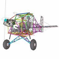
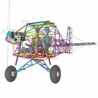
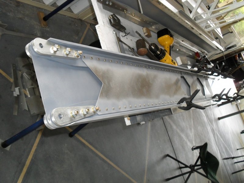
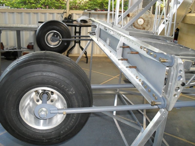
Well - thanks for the kind words. I'm quite sure that my guesstimate of the material sizes you've used for the carry through are not likely to be exact, but I still think they look a bit light ... I notice you've not said what the actual sizing is though. On closer inspection of your photos the caps are a little larger than I first thought but I'd be surprised if they're larger than 50x3 angle and since you say it's 6061T5 then at a yield strength of 210MPa they'd calc out at 21.77kg/sqmm and have a cross-sectional area of 291sqmm, giving them a capability of 6.4T - which is still only about half what you need. I'm not meaning to rain on your parade but I really think you need to build the whole carry through on the bench before 'inserting' it through the fuselage. Your photos show that you've riveted it into place via pop-rivets to the angles each side of the fuselage - that's a nice simple attachment method BTW, and quite secure enough since it can't 'escape' vertically, so only needs to be held in location laterally - but if you do plan to solid rivet the web then it'd be much easier bucking it on the bench than trying to do it in-situ. If you use pop rivets you'll be building a very limited service life airframe, they'll work loose in a short while in that highly stressed location. Just for reference I've posted some pictures below of the carry-through I used on AussieMozzie which I never completed, but which is a similar wing arrangement for a pretty much identical weight aircraft. If you compare the size of the structural members you'll see why I think you might be a bit on the light side. Note that on this carry-through I have tapered the spar cap material at the outboard ends where the load is transferred from the aly caps to the nearly 800MPa heat-treated chromoly wing attachment plates, so to compare the actual member size you need to look at the carry through near its centre rather than at the ends, but as you can see, the spars for a cantilever wing need to be quite massive, even when using 6061T6 alloy -
-
Hellsbells Gareth, the runway was built in the 1970s long enough to safely land Learjets on the valley floor. If you're so low and flat in an LSA that trees on the approaches are an issue then you need a little more practice with flaps and slipping ... just sayin'. Low approaches and/or departures at a location with very limited outlanding opportunities is a bit inadvisable, one is wisest to treat operations at such places as if they were always deadstick, ensuring you can always make it to the strip in event of loss of power in the circuit. Pearo, a cutting is where a ridge has been blasted away to make way for a road, or in this case a road and also a runway. Do you use Google Earth? Turn on the 'terrain' function and you might see a cliff adjacent to the left side of 12 ... it can produce strong rotors over the strip when suitable conditions prevail. Especially since the ridge rises steeply 1000ft higher on that northern side. Nothing to worry about unless firm northerlies are blowing.
-
No, 12 is better in almost all conditions except in a due northerly, westerly or WNW, and if it's strong then it can be quite bumpy close to the ground due to extensive areas of uneven high ground to the north and west. Also - check the windsock carefully, it may well be blowing NW in the air but the valley funneling effect can have it blowing NE on the ground. Also - be mindful of the seabreeze which comes in very strong from the East in mid-late afternoon on days when it's hot and unstable further inland. In a north easterly I'd always recommend using 12 and land long to overfly the cutting. If you've had time to check the surface on the ground then I'd always land on the grass to the right of 12 to increase the distance from the cutting itself - and grass is easier on the tyres too of course. 30 is fine in nil wind or little wind conditions, naturally. One other thing, a smallish oval RH circuit for 12 is best, avoid straight in approaches to avoid overflying the hillside villas and to keep you further away from the resort.
-
Don't forget it's right hand ccts for 12 ... and a word of warning from someone who's made thousands of landings there while instructing in the 1980s ... if there's any northerly component to the wind it can be quite treacherous ... um ... interesting ... if you're touching down about halfway down the runway where the cutting is. And that's the usual place to be touching down if you're using 12 due to high ground and villas on the approach, so if there's any significant wind and it's with a northerly component then land long so that you're touching down after the cutting. You've been warned ... ;-)
-
The XPB Stage 1 underway.
Head in the clouds replied to bexrbetter's topic in Aircraft Building and Design Discussion
Galvanized steel sheet, or more usually zinc plated steel sheet is also acceptable though I think the stainless has a slightly higher melting point. The effect of a bit of zinc burning off and breathing the gases therefrom probably wouldn't be much of a concern while you were dealing with the more pressing aspects of an inflight fire. In fact galv sheet would be a better option when the rest of the airframe is aluminium because in event of any electrolysis between the two the galv would be sacrificial whereas between stainless and aly, the aly becomes sacrificial. On a welded steel airframe like DooMaw, for example, you would probably choose stainless rather than galvanized steel sheet, though the stainless must never be welded to the chromoly frame because doing so causes localised brittleness of the 4130. -
The XPB Stage 1 underway.
Head in the clouds replied to bexrbetter's topic in Aircraft Building and Design Discussion
The general idea of your carry-through is OK but I'm a bit concerned about some of the details. I realise you've just put a few pop rivets in to hold things together at this stage but I trust you'll be solid riveting it in the final assembly? You've removed a lot of the web material at the top and bottom with multiple lightening holes in the rivet zone. I wonder whether you'd be better off leaving that material there because, apart from saving the cost of the laser cutting, it adds to the spar cap value which at this stage looks as if it's way too light. A quick calc of your spar caps - the spars look to be about 180-200mm high so the spar cap centroids are about 150mm vertically apart. I'd guess you'll have an effective wingspan of about 8m and your centre section is about 2m so each bolt-on wing will be about 3m span-wise. Consequently the half-span of each wing panel is about 1500mm providing a leverage/moment ratio of 1500:150 at the spar caps = 10:1. If your all-up weight is around 600kg then each wing panel will be carrying about 3m/8m of the total weight, minus the panel's own weight and any fuel the wing might contain = (3/8x600) - 50 = 175kg. At 6G that becomes 175x6 = 1050kg. At the ratio of 10:1 that means the spar caps must yield at more than 1050 x 10 = 10,500kg = 10.5T in either compression or tension. The spar caps shown in the pictures appear to be just architectural grade (5 series aly), which apart from having poor fatigue characteristics, has a yield strength of only around 28kpsi/190MPa = 12.7T/sqin = 19.7kg/sqmm. Therefore you need 10500/19.7 = 532sqmm of cross-sectional area at each spar cap. Well that's the theory anyway. In fact you need more than that because you need to allow for break-out values for the bolts in less-than-ideal bolting arrangements - as they invariably are when joining spar caps of angle material - and the yield strength of aluminium in compression is about 80% of the tensile yield strength, so cantilever wings typically have larger top spar caps than lower ones. Then you need to consider the buckling issues as the top cap tries to move towards the lower cap under normal upright flight loads (exacerbated by any dihedral you might incorporate). That requires a significant web stiffener at the wing attach point. Perhaps you plan to add that but your outer web lightening hole has removed most of the material where you need to attach it. Currently your spar caps appear to be something like 30x2mm angle providing a cross-sectional area of around 120sqmm which is about 4-5 times less than required. If you used 6061T6 (yield 276MPa/40kpsi) you'd need 375sqmm of cross-sectional area, or about three times as much as you appear to have used. In similar builds my carry-through caps were made from Alcan/Capral/Alcoa 2in x 1/4in 6061T6 structural angle (structural angle has a radius in the internal corner which helps resist buckling), which has a cross-sectional area of approx 600sqmm and a yield value of just over 17T. By the time bearing strength and compressive strength is taken into account it works out just about perfect for this class of aircraft. The web - in conjunction with the caps described above - and after practical testing - I found that I needed a 3mm thick web, solid riveted with 3/16 rivets at 25mm c/c (Type 2117-T4 Hard 26kpsi shear, not Type 1100 Soft 12kpsi shear, and most certainly not any kind of pop/blind rivet (around 6kpsi shear), or even commercial grade aly solid rivet which normally test at around the same as Type 1100). Also - the largest lightening holes that didn't cause a significant strength loss (in buckling) were small enough to be pointless, so I just used a solid web. Additionally - web stiffeners were needed at c/c spacing no more than the height of the web, and half that spacing at the outboard ends i.e. stiffeners about every 200mm along the web and the last 2-3 of them at about 100mm spacing. Another note on spar web lightening holes - it's important to keep the load-path direction in mind - In the part of the wing that is cantilevered - i.e. the outboard wing panel - the load direction in the web is at 45 degrees, consequently you must have your lightening holes sufficiently far enough apart (and/or small enough) to allow a 45 degree load path between them - and it's beneficial to flange the lightening holes to provide those load-paths with stiffened 'edges' which significantly helps to resist localised buckling and to stabilise the entire spar. In the spar centre-section the load path is quite different. When both wings are lifting/loaded equally (or close to equally, as they usually are) then there is a small amount of 45 degree tension in the web as the lower (in upright flight) cap tries to stretch and the upper cap tries to compress, but the far greater load is that of the upper cap trying to move toward (or apart from) the lower cap. So keeping the web from buckling under compression is the major issue, hence web stiffeners are crucial and lightening holes don't play much of a part in that area. It's very easy to underestimate the immense loads that must be resolved by the spar carry-through. Rear spar - at this stage you don't appear to have provided for it but do keep in mind that it's better to have a full carry-through than to join stubs outside the fuselage. This is to resolve uneven drag loads i.e. lozengeing of the wing/fuselage junction. And to achieve that you'll need substantial triangulation structure between the main and rear carry-throughs which in this configuration can be made from flanged sheet material and skins (rather than extrusions) to form a tough monocoque seat-base structure - hint ... consider the control runs while designing it ;-) One last thought - earlier you spoke of your firewall. I've seen practical demonstrations of an engine bay fire. Even an ignited bad fuel spray or hot oil spray (912s have external oil lines) doesn't cause too concerning a fire. That is - until you add airflow of 60kts or so, at which time it becomes a huge blowtorch. An aly firewall of 3mm thickness was shown to burn through in less than 15 seconds - then that fire is blasting straight into the cabin. After seeing that demo was the last time I used an aly bulkhead instead of a proper firewall. Firewalls must be made from stainless steel, and though stainless is a heavy material you only need 0.5mm thick stainless sheet and that is less than the weight of even 1.6mm aly sheet. And 0.5mm stainless will not melt in event of an engine-bay fire. -
DooMaw - building a STOL
Head in the clouds replied to Head in the clouds's topic in Aircraft Building and Design Discussion
June 25-26th 2016. The day job's still busy, so I only had the weekend to get a bit done on DooMaw. Following on from fitting the pedal assemblies I had to make and fit a bracket at the firewall which will secure the ends of the central pair of rudder cables - the outer pair of cables will be secured through the engine mounting plates at the firewall lower corners. On Sunday morning I was raring to go and then had what seemed to be a breakdown of the TIG machine. It refused to deliver any Argon gas through the torch. I couldn't hear the gas solenoid operating in the machine itself, so I guessed that was the problem but thought it could also possibly be at the regulator on the gas bottle. I've got the new kind of Argon bottle from BOC which has a built-in regulator so I had my suspicions, and particularly since it was our coldest day of the year so far, hovering just below 6C. I disconnected the outlet hose from the regulator and although the reg was pressured up, no gas came out. Ah ha, I thought, some valve or other doesn't want to play ball ... I got out the trusty heat gun and pointed it at the regulator from all angles until it was pleasant to warm the hands on and still no gas would exit. After about an hour of fiddling I'd just about decided that my day's welding was over and was developing dark thoughts about the conversation I'd be having with BOC about their wonderful VIPR system ... when I wondered whether it was just possible that they might have an auto cut-off valve on the outlet. I've never seen such a thing but sure enough, as I re-connected the gas line gas hissed out of it. Then it had to be in the TIG machine itself, so off came the casing. Everything looked normal except the solenoid-style gas valve wasn't operating when the foot pedal was pressed. I isolated the pedal controls and operated the switches manually, still no action from the solenoid. Judicious tapping of the solenoid with a jewellery hammer while it was powered up didn't produce any results either. With it installed it was very difficult to get enough access to test the solenoid by applying external power. I could see from the feed from the welder's power supply that it was a 24V DC unit but there was very high AC voltage nearby, so I elected to remove the valve entirely for testing. I'd unplugged the machine from the mains but I didn't like the look of some large capacitors that would probably hold residual power at a voltage enough to do me serious damage, so I dug out some very large wire-wound resistors and put them across the capacitors first. Glad I did, from the heat generated I'd say there was probably enough power in them to blow my fingers off if I'd let them stray in the wrong place. Half an hour later I had the valve on the bench - operating perfectly. There was nothing wrong with it. It took an hour to replace it and connect the gas lines securely, to be sure they were tight and wouldn't leak ... Then the phone rang and I was chatting to my brother and glancing at the now rather unpopular TIG machine when I noticed one of the switches on the front didn't look quite right. The machine is a combination MMAW (stick) welder, plasma cutting machine and AC or DC TIG welder ... and when either replacing or removing the dust cover I put over it at night or when not in use, I must have caught the switch and it was now in the MMAW position instead of the TIG position. You don't use gas-flow for MMAW welding of course ... So we now all know that it doesn't take much to make a monkey of me on cold mornings. Then, at last it was time to start fitting the tab plates which I had the laser-cutting people cut for me a while ago. They were a bit fiddly to get positioned for tacking but once the first few tacks were in place it is just a case of persistence and, for some of them contortionism, to complete their welding. The tab plates will be used to secure the aluminium sheeting for the forward part of the fuselage sides, and to attach the engine cowling. These tab plates are necessary to avoid drilling holes in the CRMO tubing which would weaken it and also moisture would get inside which would allow internal corrosion to develop. There are thirty two of these tab plates to fit and I got eight of them done in the rest of Sunday, so I guess there's a couple more full days needed to finish them off. I'm starting to see the light at the end of the structural work on the fuselage (no, not the navigation light), at which time I can get the epoxy coat on and stop having to be so careful about moisture protection. The remaining jobs are starting to get short enough to list - Finish the tab plates Make and fit the throttle bar and supports Similar for the choke Make/fit hinges for the doors Make/fit latch plates for the doors Add cleats to secure the fuel tank(s) Fit the flanged cabin-top plates made previously to support the clear cabin roof Design/make/fit the cabin-top aileron control attachments Design/make/fit the flap control attachments ... and probably a few more things I haven't thought of yet. Some pictures - The VIPR gas regulator holding pressure though the delivery gas line is disconnected - The cable termination bracket for the central pair of rudder cables - Tab plates underway - Not counting the time spent on the welder 'problem' it's just another 10 hrs for the log, making a total of 1119 hours so far.
-
DooMaw - building a STOL
Head in the clouds replied to Head in the clouds's topic in Aircraft Building and Design Discussion
This is all very nice folks but you're 'chatting' on my build log. Could we keep the discussion relevant to DooMaw and/or good engineering practices, thanks. -
DooMaw - building a STOL
Head in the clouds replied to Head in the clouds's topic in Aircraft Building and Design Discussion
May 30th to June 19th 2016 - A while since the last progress report due to the day job being rather busy and so I've not had much time to devote to the DooMaw build. I did manage to get a bit done in stolen hours here and there, and during parts of the weekends. At present I'm trying to finish off a multitude of partly completed tasks. Some while ago I made the pedal sets but had to make a couple of small changes to make them more readily dis-assemble-able for servicing, and I still have to make the recoil-style balance springs for them. In the most recent previous progress reports I showed hardware that I'd been making and installing for the rudder cables, so now that I'm equipped with the cable and swaging gear I showed earlier I was able to start running the cables and making their end fittings. Concurrent with that I made up the top tail bracing wires using the tensioning fittings shown last post, and then I could devise the quick-release mechanisms for the lower wires, so that the horizontal stabiliser and elevators can be folded quickly using the all-important pylon500 hinge! Very time consuming making all the small components for that, if I didn't enjoy doing it, it'd be a far more profitable use of time to do more of the CAD work in advance and send it off to be laser cut instead. The quick-release is based on the pelican hook concept such as is used for the releasable cargo hook on a helicopter, or a bomb-release mechanism. I'm happy with how mine work but I'm going to re-make the actual hooks and the hook retainers because I'm not 100% happy with their geometry, but that's a minor job for another rainy day. Once I'd finished all the rudder and tailwheel steering cables, working from the tail forward, I could finally position the pedals assemblies and mark and drill the floor to secure them. It took a bit of time to get them right because I wanted the full forward adjustment position to be as close to the firewall as possible without the pedals, brake pedals or brake hydraulic cylinders actually hitting it regardless of several variables. I also wanted to install thin stainless steel slider plates between the floor hold-down screws for the pedal-bar supports to bear on so they don't wear the floor timber in use. When I got all that set out it was an anti-climax actually drilling the eight bolt holes ... then I could locate the positions for welded brackets to be installed at the firewall which will secure the forward (static) ends of the rudder cables. Once those brackets are made and installed the pedals will be able to operate the rudder via those S tubes described earlier. Before I can do that though, I have to paint the final epoxy coat on the pedals because once the forward end fitting is swaged onto the rudder cable I can't remove the cables from the pedals without cutting them because the end fitting can't be pulled through the S tube. Last job before the big rains yesterday was to measure and divide the elevator pushrod which, as discussed previously and well pointed out by pylon500, was too long in one piece. I'd previously machined up another pair of the rod-end fittings and made the centre walking beam, so it was just a case of accurately marking the pushrod above the centre of the walking beam's travel with the elevators set neutral, marking the portion of tubing to be removed to accommodate the length of the new rod-ends - and cut the tube. It also provided me with the chance to do something that had been nagging me because I forgot to do it when I originally made up the pushrod. I'd forgotten to paint the interior of the tube to protect it against corrosion, and that was a very remiss omission given that the tubing is only 0.9mm/0.035" wall thickness, so even a very slight amount of corrosion could make a significant difference to its serviceability. Painting the interior presents its own set of difficulties, I've tried with various kinds of swabs before without very satisfactory results and I've seen attachment full-circle nozzles for spray cans that do the job but didn't have one or know where I'd locate one ... so I put a bolt in the rod-end thread to block it and taped over the rivets with PVC tape and poured a cup full of 50% thinned etch primer into the tube then rotated it in a set of padded V blocks that were set not quite horizontal, so that the paint was just slightly pouring out of the open end into a catch can, it worked perfectly. Then I inverted the tube for a few minutes to drain all the excess and set up my heat gun blowing through the tube on warm setting for a few minutes to dry it and evacuate any remaining thinners. The thinners and heat gun combination didn't make the workshop blow up which was pleasing, and I was able to rivet the new rod-end fittings in and install the two pushrods to the walking beam. A few photos - The first three show the harness attachment cleats, shoulder belt attachments at the back of the baggage door, they'll have crossed cables so that each cleat shares the load of both occupants. The lap belts are attached to cleats on strongpoints near the strut attachments. The next picture shows the antenna support plate. The harness cleats and this plate were installed a while ago but I forgot to takes pictures at the time. The pedal assemblies in place The elevator pushrod now divided in two, and showing the centre walking beam straddling rudder cable guide pulleys Tail bracing, and showing quick-release mechanisms for folding the tail 37 more hours for the log - 1109 hours so far.
-
Essential flight bag items
Head in the clouds replied to Parkway's topic in AUS/NZ General Discussion
Erm ... well I hadn't noticed anything particularly subtle about it yet. And the irony wasn't missed, I live ten minutes from Mt Tamborine. ELB is what they are - Emergency Locator Beacon, there are Personal types which are wearable and distinguished from the types fixed to the airframe (or vessel) by becoming known as Personal LBs, but they're all ELBs. Humour aside, there are some folks who are flying machines that take them on cross-countries further than the end of the cross-strip, so in respect of the OP's request for information I simply directed him to an earlier thread, some posts of which contain valuable information, should anyone be unfortunate enough to end up needing it, and particularly if there happened to be injuries involved. Somewhat paralleling the survival kit is the matter of crashworthiness of the airframe itself. Interestingly, although we had plenty of crashes in the early days, often in simple, exposed airframes like the B1rd, but due to the considerably lower speeds a much smaller percentage of crashes resulted in serious injury or death, than they do these days. There are a few things people can do to improve their chances and quite a number of them are listed in this thread which is also worth re-visiting - Small aircraft crashworthiness -
Essential flight bag items
Head in the clouds replied to Parkway's topic in AUS/NZ General Discussion
PLB (ELB?) is a given isn't it? You are required to carry one if you're going more than a stone's throw from your point of departure so the list of things for the survival pack are items you might need in addition. It depends how far you're going of course. If you're headed up Cape York, to the NW Kimberley coast or the SW Tassie coast you'd do well to take more than a firestick and a pack of sultanas ... I know someone who had and used a working ELB when they had an engine failure over the Great Sandy desert and although his predicament was known, even in that relatively accessible location it still took three days to get to him, locally available choppers didn't have the range. It'd be quicker these days but could still take longer than might be comfortable in mid winter or mid summer. -
Essential flight bag items
Head in the clouds replied to Parkway's topic in AUS/NZ General Discussion
We had a similar thread a while ago, you might get some inspiration from it, and it might be good for the rest of us to re-visit it for a refresher too - Survival Pack


.JPG.c87ab337ebd6164e0ae9fe341450b52d.JPG)
.JPG.8b6ac242c53ef0dd2a5f053d0f11a2bb.JPG)
.JPG.18d86a8535a51410d2afbc5cb1d26f6b.JPG)
.JPG.994ef194726bd34477f2483a1911b851.JPG)
.JPG.44e3d70003d869dcde8e0dec246ce484.JPG)
.JPG.ab51f93b25f8afb6ee249f4f085ebff9.JPG)
.JPG.5db23e0410c46afe82a9c489c512499d.JPG)


.JPG.3a8a63da418ea1e063bc82b645ff8c05.JPG)
.JPG.185418b604b53ab614251ca09bea5a05.JPG)
.JPG.1887597f88e33edc3d36e035b7eae60b.JPG)
.JPG.a2eb584cb8716c4d2363a813bbbbdf22.JPG)
.JPG.7fc2ede161754d603fc4bb9e8413b225.JPG)
.JPG.4a2dc5ceac0d806863af28af32572863.JPG)
.JPG.9ac9138b6e70857b4703796d8dbf2630.JPG)
.JPG.047fa77a80605c55767810c4540986c0.JPG)
.JPG.c1c19449cc7ad0cb912565e017556771.JPG)
.JPG.4e0db9eefcf743e508f70c949454974c.JPG)
.JPG.194482bc8e36ab953f539b54930eee8f.JPG)
.JPG.727021e29da341f89345a30eb3649c71.JPG)
.JPG.6c1f421c60f41942887c5cebc658d5e0.JPG)
.JPG.6bb31b87b48a3214f3228a24bd1b242c.JPG)