
Head in the clouds
-
Posts
1,842 -
Joined
-
Last visited
-
Days Won
42
Content Type
Profiles
Forums
Gallery
Downloads
Blogs
Events
Store
Aircraft
Resources
Tutorials
Articles
Classifieds
Movies
Books
Community Map
Quizzes
Videos Directory
Everything posted by Head in the clouds
-
There seems to be a bit of confusion about straight-in approaches. It's stated in the Visual Flight Rules Guide that SIAs aren't recommended but they're legal because they're conditionally provided for by CAR166B. The complete VFRG text for correctly making SIAs is pasted below - Straight-in approaches – Straight-in approaches are not a recommended standard procedure; however, CAR 166B allows pilots to make straight-in approaches providing they meet certain conditions: pilots who choose to adopt a straight-in approach should only do so when it does not disrupt or conflict with the flow of circuit traffic on a straight-in approach, the pilot must give way to any other aircraft established and flying in the circuit pattern at the aerodrome (pilots on the base leg and before entering the final leg should be vigilant that no traffic is on long final for landing) before making a straight-in approach, pilots must determine the wind direction and speed and the runway in use at the aerodrome. There are several ways to do this: automatic weather station (AWS), aerodrome weather information service (AWIS), automatic aerodrome information service (AAIS), CA/ GRS or UNICOM radio contact with a ground-based radio communication service, company agent, approved observer [CAR 120], or aircraft currently operating at the aerodrome or visual indications if the information cannot be determined by the above means. [*]pilots must assure themselves, by other means, of the aerodrome’s serviceability and other hazards which are usually indicated by markings adjacent to the wind indicator [*]on a straight-in approach, the aircraft must be established on final at not less than 3 nm from the landing runway’s threshold. Pilots should include their intention to conduct a straight-in approach with their inbound broadcast. Also make a further broadcast of intentions when not less than 3 nm from the runway threshold. Pilots making a straight-in approach should observe the following: do not commence a straight-in approach to a runway when the reciprocal runway is being used by aircraft already established in the circuit only minor corrections to speed and flight path, to maintain a stable approach, should be required within 3 nm on final. The aircraft’s transponder should be squawking Mode C or ALT. The aircraft’s external lights should be illuminated and remain on until the aircraft has landed and is clear of all runways an aircraft established on the base or final leg for any runway has priority over an aircraft carrying out a straight-in approach. The twin-engined pilot at Narromine did not properly meet the criteria for an SIA because he shouldn't have asked anybody if he could do so, instead he should have broadcast while inbound that he was intending to do so and then determine wind direction, service runway and that there was no other traffic established on BASE or FINAL (see the last line of the quote in red above). Before three miles out he should have then broadcast that he was "established on SIA for runway XY". At that point he would then gain priority over all other traffic in the circuit (given that there wasn't any traffic already on base or final) i.e. any traffic that might be in the circuit would be on the crosswind or downwind legs, and they would have to extend their downwind leg to accommodate the twin.
-
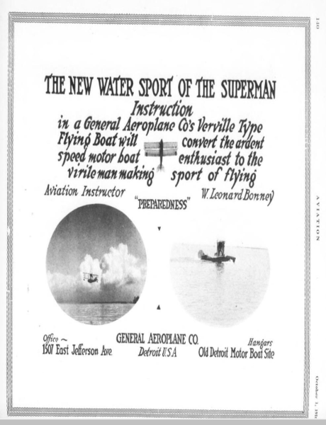
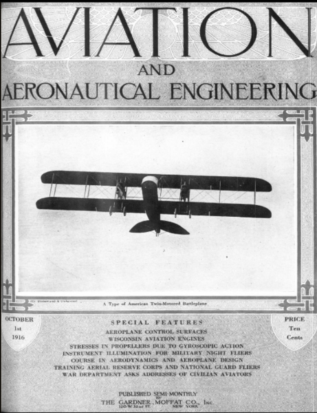
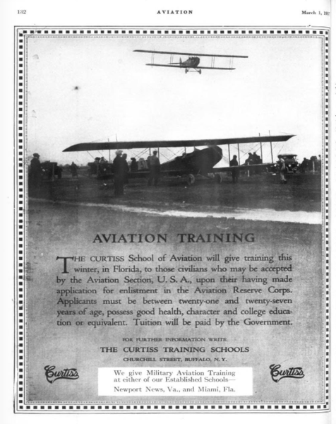
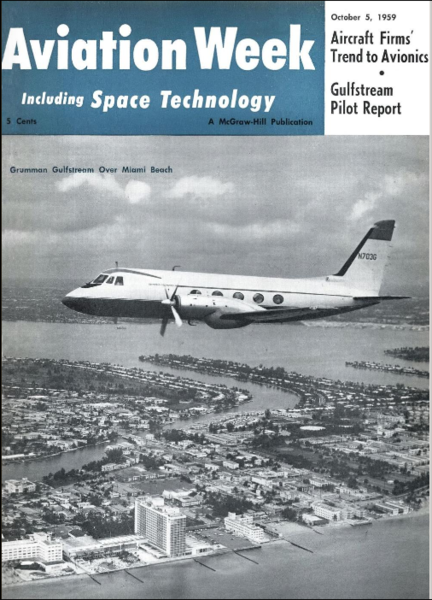
PURE GOLD! If you use the search term 'Aviation' and keep scrolling down you will come across what appears to be every copy of America's premier aviation magazine of the time, Aviation Week, from 1916 to 1960, fascinating reading. Over that time-span the changes are astounding and it covers, of course, WW1, the remarkable developments of the 1930s, WW2, the Korean War, VTOL developments, early space exploration as well as the private, recreational, homebuilt side of things throughout the whole period. Everything's downloadable in various formats too, see the links at lower right of each page. A few example pages, I love the first advertisement -

-
DooMaw - building a STOL
Head in the clouds replied to Head in the clouds's topic in Aircraft Building and Design Discussion
October 3rd 2016. Yesterday I made the mass balance for the trim tab. I balanced the control surface on its hinge line and added test weights to find out how much weight was required, then added a nominal 10% to account for the weight of the fabric covering. Once I knew the required weight I worked out what volume it would be and made up a torpedo shaped template so that I could picture the size and shape that the weight would be. It isn't critical that the weight be exact, within 10% or so is quite close enough, so I then turned a free-hand shape out of acetal on the lathe and cleaned it up with a single-cut file to remove small imperfections and give it a good finish. I drilled and tapped the narrow end so that I could use a 3/16 machine screw to hold it in place while making the mold. Next I turned up a tapered piece of PVC, this would be used to form a gallery into the mold to pour the lead into the cavity. I mounted the acetal and PVC parts to a piece of 2mm aly sheet and then went in search of a suitable container to make the mold in. Those small disposable plastic cups that are used to hold water from a water chiller would have been ideal but I didn't have any so I found a small 'tupperware' which was the right size. I forgot to mention, I was making the mold from silicone, as it's so quick and convenient for one-off molding of lead. Provided you don't overheat the lead, silicone easily manages the heat of molten lead. Lead melts at 330°C and most documentation has silicone melting at around 300°C but it copes with higher temperatures for short periods, so if the lead is 'just melted' and then poured quite quickly so that it doesn't freeze up during the pour it works fine. One caution though, the relatively high temperature does cause the silicone to give off some vapour which affects the surface finish of the lead, so if you want fine moldings it's not the best way to go. If you wanted a better surface finish you'd need to go down the Plaster of Paris road which is rather more arduous because you can't pull the mold off the positive to leave an empty cavity so you have to make an indexed split mold or use the lost wax process, and make sure you bake the plaster mold in a low temperature oven for a few hours to dry it completely before pouring the lead or the heat from the lead will boil any moisture in the plaster and the steam will eject the lead violently and/or explode the mold, either way probably spraying you with liquid lead and causing horrific burns ... beware! I mixed up a quantity of platinum cure 2 part silicone, filled the plastic container and immersed the mounted plastic parts in the silicone. The silicone takes about half an hour to cure sufficiently to de-mold the plastic parts. Before mixing the silicone I had sprayed all the parts including the container with Ease Release mold releasing agent, so to get the mold out of the container I just had to put the nozzle of an airline between the side of the silicone and the container and blow it out. Once the silicone was no longer constrained by the container it was simple to just pull the plastic parts out of the elastic mold. I then created a set-up with the mass-balance support tube dangling into the hole in the top of the silicone mold, heated some lead in an old steel spoon using a gas ring below and a small blowtorch above, and poured the molten lead into the gallery created by the tapered PVC piece. Once the lead had cooled sufficiently I broke the lead sprue off at its narrowest point and pulled the silicone mold off the mass-balance. The last photo shows the control surface now balancing level. After that photo was taken I lightly dressed the surface of the lead with a fine rasp and it's ready for painting - Six hours of fiddling about, a total of 1303 hours so far.
-
DooMaw - building a STOL
Head in the clouds replied to Head in the clouds's topic in Aircraft Building and Design Discussion
September 24th - October 2nd 2016. Before starting the epoxy coating of the airframe I wanted to drill the holes in the elevator ribs which will attach the elevator trim tab hinges. I'd intended to have a trim tab attached to the elevator trailing edge. Having drilled the holes I realised that it was going to be very difficult to have a neat arrangement for the push-pull trim-tab control cable due to the need to curve it along the elevator hinge-line then immediately curve it back again so that it then followed the horizontal stabiliser folding hinge-line (for when the stabs are folded up). So - I decided I'd be better off with an inset trim-tab and run the push-pull cable along the inboard edge of it next to the rudder, then the cable could flex with the operation of the elevator, and would already be in the line of the hinge for the stab folding up. As you can see, I made the trim tab quite large, and that's for two reasons. Firstly, to ensure it has plenty of authority to control the elevators at the low speeds DooMaw should be capable of, and secondly, so that only a small deflection angle is required because the more you deflect the tab down, for example, to trim the nose up, the more the tab detracts from the elevator's own power because the tab is providing a reflex to the airfoil shape, so the less deflection the tab has, the less it reduces the elevator's own effectiveness. I cut the tab out of the aft portion of the port elevator, made up bushings and rear/front spars for the elevator and the tab and welded it all back together again, including using a piece of copper strip as a backing while welding up the holes I'd drilled earlier. As part of the fail-safe design of DooMaw all control surfaces will be 100% mass-balanced, so the trim tab has its own mass balance as you can see from the 1/4" tube projecting forward under the elevator. It will have a torpedo shaped piece of lead of approx 100g cast onto it. Then the elevators themselves will have mass balances attached to the aerodynamic balance forward of their hinge line. These balance weights are not only for flutter resistance. The trim-tab would probably be well within its flutter excitation speed at normal cruise should it have a control disconnect so the tab's balance weight is crucial but it's probable that the flutter speed of the elevators would be above the Vne, considering they have aero-balance tabs. So - the reason for the balance weights on the elevators is to ensure that in event of an elevator control disconnect, for whatever reason, the elevators can be controlled throughout the speed range by the trim tab. It's all very well being able to control the elevators via trim at cruise speed but as you slow down for a landing the weight of the elevators makes them hang down if they aren't mass balanced i.e. induces 'down elevator', so as you slow down the nose keeps dropping and that requires more trim which in turn is less effective at lower speed and so on. Consequently, if your elevators aren't mass balanced and you need to make a landing using trim only then you're forced to make a very fast landing. The mass balances will probably be about 2lbs/1kg each but well worth the weight penalty for the added safety, in my mind. So today's project is starting on installing those mass balance weights, time to make molds and start melting lead. Some pics to help tell the story - Another 19hrs in that, 1297hrs in total so far.
-
DooMaw - building a STOL
Head in the clouds replied to Head in the clouds's topic in Aircraft Building and Design Discussion
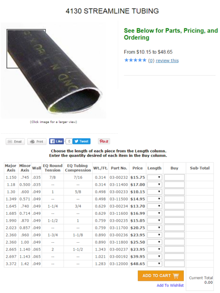
Strut buckling calculation - A strut in compression i.e. under negative G loading would normally fail as a result of structural buckling rather than compression failure of the metal itself. There are various formulae used for calculation column buckling, I've used the Euler Column Buckling Formula - F=nπ²EI/L² Where - F = allowable load n = a factor accounting for the column end conditions E = the modulus of elasticity of the column material L = the unsupported length of the column I = the moment of inertia Among the above the unknown which we want to find out is the allowable load 'F'. Regarding 'n', the column end conditions, in DooMaw's case for a buckling calculation each strut needs to be considered to be two struts (or columns) because DooMaw will have jury struts supporting the centre of the strut so each half of the strut needs to be calculated separately. Without jury struts the long slender strut would buckle very easily under negative G loading. There are various end conditions to consider and each of them affect the way, and how easily, the column will buckle so a factor 'n' is applied to the rest of the formula to account for the way the ends of the column are supported. For examples, if both ends of the column are pivoted (pin jointed), as most struts are, then the factor is 1. If one end of the column is held rigid (embedded in concrete perhaps) and the other end is pivoted, you can imagine that the stiffness at one end would increase the column's resistance to buckling, so the factor is 2. If both ends are held rigid (like a steel column embedded in concrete at both ends, between floors of a high-rise building perhaps) then the stiffness provided at both ends increases the resistance to buckling even more, so the factor is 4. Another condition might be where the column is held rigidly at one end but not supported at the other end at all (like a flagpole embedded in concrete and supporting a heavy weight sitting on the top), you can imagine that a column in that condition might buckle very easily, so the factor is 0.25 ... and so on. In DooMaw's case, each end of the strut is pivoted but the centre of the strut is held rigid by the jury struts, so we can consider each end separately as columns that are half the length of the complete strut and where one end is held rigid and the other is pivoted, so the factor we use is 2. E - The more elastic the material of the column, the more easily it will buckle. You can imagine that a rubber column would buckle more easily than a steel one of the same dimensions. The modulus of elasticity for any material is found in its Materials Properties data. In the case of 4130N chromoly it is 205GPa/29,700ksi (i.e. 205,000MPa/29,700,000psi). As a matter for comparison the modulus of elasticity for 6061T6 aluminium, of which many LSA struts are made, is 68.9GPa/10,000ksi which is only about a third of that of chromoly i.e. aly is three times more elastic than chromoly, so you can immediately see why aluminium struts need to be so much larger than chromoly struts. L - DooMaw's struts are 8ft (96") long but they are supported in the middle by the jury struts, so the unsupported length for the formula is 48". I - The moment of inertia is determined by another formula and is affected by the diameter of the column and the thickness of the wall (assuming the column is tubular). If the column is round we only need to calculate its buckling in one direction, if it is ovaloid it would normally buckle in the direction of the narrower (minor) axis but we would need to take into account the end conditions i.e. it might be pivoted in the direction of the major axis but rigid in the direction of the minor axis. In DooMaw's case it is pivoted in the direction of the minor axis which is the worst case, so we calculate it that way. As you can see from the image posted below, the streamline-shaped strut I am intending to use has similar value buckling characteristics to that of a 1" diameter round tube of the same wall thickness, so we use the dimensions of a 1" round tube for the moment of inertia formula - I = π(do^4 - di^4)/64 Where - do is the outside diameter of the column di is the internal diameter of the column Note - do^4 means the outside diameter to the fourth power i.e. do x do x do x do, similar for di^4 (my keyboard allows second and third power do² do³ but I can't find the alt code for fourth power ... anyone?) So the moment of inertia of DooMaw's strut is 3.142(1 - 0.66195)/64 = 0.016596 We can now apply all the variables to the Euler column buckling formula - F = 2 x 3.142² x 29,700,000 x 0.016596/48² and that would give us the allowable load in lbs = 9732003/2304 =4224lbs From the previous post we recall that with MTOW 800kg at1G the strut is loaded with 1338lbs, so to determine the G at which the strut will buckle we divide the allowable load by the load at 1G = 4224/1338 = 3.15G. My C172 in the utility category was rated at +4G -2G, so with the applicable safety factor of 1.5 it would have been capable of around +6G and -3G at yield. From the above two posts we can see that the chosen strut size for DooMaw will exceed the C172 G capability by about 50% in positive G and is around the same as the C172 in negative G. We don't hear of Cessnas losing their wings so I'm quite satisfied that the chosen strut size will do the job admirably.
-
DooMaw - building a STOL
Head in the clouds replied to Head in the clouds's topic in Aircraft Building and Design Discussion
Calculations ... It's about time for me to organise another couple of orders from the US. I need a lot of fasteners, a couple of instruments, covering materials, some bearings and the airfoil shaped tubing for the struts from AS&S (Aircraft Spruce and Specialities), and from FBI (Freebird Innovations) I need the toe-brake cylinders and some other brake parts. Mostly it's just a matter of making lists and trying not to miss anything out because the freight costs are quite high, so you don't want to be having to make another order for a couple of small parts you didn't think of in time. The struts are the main consideration just now and there are many sizes (and prices) available. Originally I was going to use aluminium extrusions but the folding wing mechanism on DooMaw is quite complex and if I use aly sections for the struts then the end fittings have to be bolted in, and with the folding mechanism it would make the strut ends quite bulky. By using 4130N chromoly I can weld the ends in and make them far more compact. If one had a completely free hand in the design of an aircraft, one would calculate the desired characteristics of the strut and then have the extrusion made to suit. That might work if you were planning on building a few hundred or thousand similar aircraft but it certainly isn't feasible for a one-off design, so there's no point calculating the ideal strut characteristic, instead I need to choose one of the available sections and calculate how it would perform in this particular application. If it proves to be way too strong i.e. over-engineered then I'd calculate the next size (or two) down, or v.v. The other major factor to consider is the huge price differential between almost identical sections. For example (chromoly comes in imperial measurements) 1.99"x 0.87"x0.049" streamline 4130N chromoly tubing (that's about 2in/50mmx 7/8in/23mmx 49thou/1.2mm - the last size is the wall thickness) is about US$15/AU$21 per foot/300mm. Whereas 2.023"x0.857"x0.049", which is virtually identical in size and strength properties, is US$21/ft or AU$30 per foot/300mm. At 300kts the extremely slightly narrower latter one might make a tiny difference in drag but at 60kts or so there wouldn't be any difference at all between the two, except the narrower wallet during the build ... The sizes discussed above are in the mid-range of the available sizes and I had a reasonable idea that they would be in the ballpark of my requirement, and the US$15/ft one is also the most popular and hence best value for money, so my calculation just needed to make sure it was sufficient for the need. At first look it appears really quite small, we're all used to seeing the struts on our sport two seaters being about twice the size of these i.e. more like 4-5"/100-125mm front-to-back and perhaps close to 1.5"/38mm thick. There are two considerations there - most struts we see are aly extrusions and the 4130 is way stronger - particularly in its resistance to buckling under negative G - and most struts on our sport planes are probably quite a bit oversize so they 'look right' to keep the customers happy. My justification for suggesting that is no more than a simple comparison between the struts on a C172 with a MTOW of around 1000kg and the struts on an LSA with a MTOW of 600kg, the LSA struts are sometimes larger than the Cessna's! So - first the positive G calculation - I'll do it all in imperial because I'm more used to doing it that way but anyone who might want to use metric units for their own project would just substitute the equivalent metric values into the same formula. Where planes are concerned I don't try and calculate everything exactly, not only is it rather tedious but there are many variables, so instead of being totally anal and trying to get to the lowest possible value for each and every part, I deliberately err on the side of safety and round everything up rather than down, so - First we need to know the load in the strut during level (un-accelerated) flight. DooMaw's struts are attached at the 60% outboard point of the wing i.e. there is 60% of the wing between the fuselage and the strut point, then the remaining 40% out to the wingtip is cantilevered out from the strut point. A very simple method to determine the proportions of the load being carried by the strut, and by the wing/fuselage attachment point, is by considering what would happen with a free-wing. If the strut was attached at the 50% span point then the wing would fly equally balanced on both sides, so it would fly level. As we move the attach point outboard, the inboard portion of the wing produces more lift than the outboard portion so the inboard portion would start to fly higher. By connecting that inboard end to the fuselage it allows the fuselage to take some of the lift load and keep the wing level. So - if we have 40% of the wing outboard of the strut we can reasonably say that the strut is carrying that 40% of the total wing lift load plus another 40% of it inboard of the strut, which leaves 20% of it being carried by the fuselage, so the strut is carrying 80% of the wing's total lifting load. Then - the strut is at an angle of 60° and just like the G loading at 60° bank angle, the load in a strut is doubled if it has to support the wing when attached at that angle - and that also imparts a compression loading in the wingspar, but we'll deal with the wing components separately later. Just in case we eventually get an increase to the weight restriction I'll calculate this lot for more than the current limitations, and perhaps a bit more than the suggested 750kg, who knows, sometime in the distant future someone might own this plane and convert it to VH category and want to put an 0-360 in it, so let's work on say, 800kg, and see how that pans out. Say the all-up weight was 800kg, then one wing would be carrying 400kg. Well not quite actually, because the wing itself would weigh at least 20kg, so the wing is actually carrying its own 20kg plus 380kg, and the strut is carrying 80% of that, which is 304kg, but we have to double that due to the 60° strut angle, so at 1G the strut has a loading of 608kg which is 1338lbs. We know from a manufacturer-supplied table that the 4130 streamline tubing size I described above is equivalent to a 1.5" round tube, so we can calculate the circumference using the 2πr (or πd) formula i.e. 3.142x1.5=4.713". Then we multiply the circumference by the thickness of the wall to arrive at the cross-sectional area of the material in the tube i.e 4.713x0.049=0.2309in². From Materials Properties data for 4130N steel we can find that chromoly has a tensile yield strength of 460MPa and being an old-schooler I convert that to psi (1MPa = 145psi) so the yield strength is 460x145=66,700psi. In our strut we have 0.2309in² of cross-sectional area so the strut will have a yield strength of 0.2309x66,700lbs = 15401lbs. From the earlier calculation we know that at 1G the strut is loaded at 1338lbs and it won't begin to yield (stretch) until 15401lbs so to determine how many Gs it is capable of we divide its yield strength by the load at 1G i.e. 15401/1338=11.51G. So even if we very conservatively said the strut was carrying all the lift load, and the fuselage not carrying any of it, the strut would still have a positive G capability of 80% of 11.51G = +9.2G which is a safety margin of 50% above the +6G service this aircraft is designed to. And - remembering that's at 800kg MTOW. Next post I'll detail the negative G condition which is a bit more complicated. -
Vale Steve Robards "ozzie"
Head in the clouds replied to David Isaac's topic in AUS/NZ General Discussion
Really saddened to hear this. I met Steve a couple of times back in the 1980s and he was a very memorable fella full of enthusiasm for everything to do with aviation, and certainly one of the active pioneers of the ultralight fraternity. RIP Steve. -
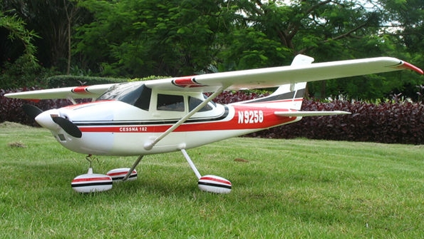
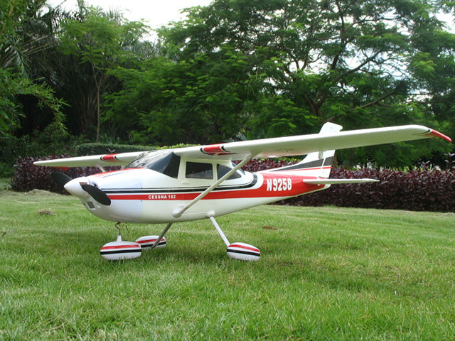
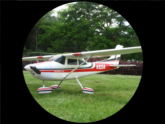
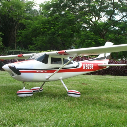
IMHO a round shape is fine but it doesn't lend itself very well to pictures of aeroplanes. For those who perhaps don't fly and have a portrait of themselves, or whatever, round works very well. A few days back I saw FT's avatar in a round border and I thought it suited him very well ;-) However, since aeroplane pictures are usually taken in a three-quarter view, the subject matter, i.e. the plane itself, tends to be a shape which is much wider than its height. Consequently, if you want the largest image of the plane and the least wasted space around the subject, assuming you don't want to crop away a lot of the subject, i.e. the plane's wings and/or tail, then you really need an avatar shape that is wider than its height - it looks like 4:3 or 16:9 would work best. Here are some examples, using the same master image each time and including the most of the subject possible in each case. For the round one it was impossible not to crop some of the subject, i.e. the wings, due to the limitations imposed by the master image. In the examples below the square one appears to give the best picture of the subject but note that it also has lost some of its wings due to the limitations of the height of the master image. The 4:3 probably works best among these images of the same overall width but the 16:9 is the most 'efficient' in terms of utilising most of the space on the image for the subject matter and least on the background. Master image Round Square 4:3 16:9 EDIT - I've added another 16:9 cropped the same amount as the square and round images for a direct comparison with them of the amount of the subject you get on a wider aspect ratio image -
-
DooMaw - building a STOL
Head in the clouds replied to Head in the clouds's topic in Aircraft Building and Design Discussion
September 18th 2016. Thanks for the kind words fellas A notable milestone was reached yesterday when I completed all the welding on the main part of the fuselage frame. That means I can start the epoxy coating as soon as we have a fine day with low humidity. It will be a pleasant relief to know that the steelwork is sealed away from moisture and I won't have to be so vigilant about rust protection. More to the point though, is that once the frame is painted I can begin the final assembly of all the other components I have built along the way. The floors can go in, then the adjustable pedal assemblies, the control column, instrument panel, control cables with their associated pulleys, bellcranks and walking beams. It will really begin to feel like I'm over the hump and coasting downhill by then. Then, eventually, after I build a new carport for the 4WD so that DooMaw can take over the garage/workshop, I will be able to sit it on it's real gear legs instead of the temporary dolly wheels/legs it's on now. It has to be on these wheels for now because the real landing gear is too tall to allow the fuselage to be stored under the house when I'm not working on it. The next main structure I'm now finalising is the engine mount. Those of you who have built your own plane from scratch or from kits might be able to contribute here - how much side-thrust and down-thrust do your engines have? Each design is different of course, the amount of side thrust is determined by the power of the engine, the length of the fuselage (that's over-simplifying it but is close enough for our purposes), and most particularly the ratio of fin/rudder area above the fuselage longitudinal datum compared with the amount of area below it (again, in simple terms). Most of our planes are fairly conventional in their design, so we can make reasonable comparisons between them. At 100hp and with the fuselage length I have and with the approximately double the fin/rudder area above the datum, it would appear that I need between 2-3 degrees of right thrust. I moved the engine mount around in CAD and when incorporating 3 degrees it looks an awful lot. It's one of those things when building the engine mount though, that is quite important to get right or at least very close, because it's not easy to fix or adjust later. You can, of course, just add packing washers where the mount bolts to the firewall or at the mounting rubber locations but that moves the front of the engine sideways and then the propeller hub would be off-centre. Consequently the mount must be initially set-up so that the engine is rotated at the hub, not at the back of the engine where the rubbers are. Since the 3 degrees looks too much I reduced it a little, to 2.5 degrees and I can certainly adjust half a degree at the mounting rubbers later if I need to, without unduly upsetting the hub position in relation to the centreline of the cowling. But I would be very interested to hear from those of you who know at what angle your engines are set. I've also incorporated 1 degree of down-thrust to compensate for some of the nose's tendency to rise due to increased airspeed as the throttle is increased. I favour that tendency anyway in a plane of this kind, because when you increase throttle it's usually with an intention of climbing rather than just going faster - in a Spitfire it would be a different matter altogether ... (love your new avatar Marty ) So - yesterday's progress - first I added a couple of tabs to which I can later attach P clips and/or saddles to hold the throttle, choke, carby heat and cabin heat cables so that they don't flop around in the foot-well. Next I pressed a bend into the bottom of the flap controller plate I'd made previously, so that it sat flat against the cabin-top side rails that it was to be welded to. I drilled the centre holes in the cabin-top side plates in the location of the flap torque-tube and used them to thread a long 1/4" steel rod through, to position the flap controller plate in the correct alignment, clamped the controller plate and tacked it in position. After I'd tacked it in four places I found that it had moved! It was only about half a millimetre but it was enough to make the 1/4" rod tight in the three holes it passed through. The locations of the tacks were quite inaccessible even for a small grinder so the only option for removing the plate was to break it away from the tacks and since the tacks were quite strong it would mean substantial damage to the plate and probably having to re-make it. Since it was such a small amount out of position, I decided that with careful use of the welding order I would be able to make the natural shrinkage of the welds pull it back into alignment, so I changed the usual welding order so that I would complete all the welding on one side first, rather than doing some on one side then some on the other side, which you would normally do to prevent it pulling out of line. The process worked well and pulled the holes back into alignment. I also used a small holesaw to cut three access holes in the sides of the cabin-top plates so that I could get paint to the inner face of the flap controller plate, those holes will serve as inspection holes later and need only be covered with 100mph tape, since they will also be covered by the inner rib of the wing-root. A few pics - A couple of tabs for 'P' or saddle clamps to hold the cables Flap controller plate fuselage welding finished and ready for epoxy coating
-
DooMaw - building a STOL
Head in the clouds replied to Head in the clouds's topic in Aircraft Building and Design Discussion
September 17th 2016 - Yesterday was a good day. As I mentioned earlier the auto-connect/disconnect system for the ailerons and flaps when the wings are folded and unfolded was the last matter still playing on my mind, until last week. In the previous post I described the 'Dogbone Method' and the machining of the parts for it last weekend. The last remaining minor concerns I had were the effect welding would have on the metallurgy of the steel that ball bearings are made from, and whether I would be able to make good enough welds on such small components, while also keeping the parts perfectly aligned so that the assembled items ended up within close tolerances. The crossbars needed to be quite perfectly square to the shaft. To satisfy myself about the issue of welding 4130 CRMO tube to the ball-bearing I decided to make a test piece first. Previously I mentioned that I would anneal the drilled balls prior to welding them but having given it further thought there would be little point as they would reach cherry red during the welding, so it would be the rate of cooling that would affect the hardness and temper of the completed part. The concern I had was that the balls and the CRMO are both high carbon steels and if they cooled too quickly, and with the (probably) fairly high chromium content in the steel the balls are made from, the welded joint could exhibit brittleness because 4130 doesn't like to be welded to high chromium content steels, especially stainless steel. The degree of brittleness I'd end up with was a complete unknown, though I had already determined that these balls are not stainless. So - among my 'things' I found a ball-bearing, not as large as the ones to be used for the dogbones, but large enough for the purpose, and I welded it to a piece of 3/8" CRMO tubing. I was careful to allow it to cool in still air. The steel the ball was made from was quite different to weld from welding CRMO, it welded more like mild steel, but didn't show any noticeable reluctance to meld in the puddle. Once it had cooled I put on a face shield in case it shattered under the crude test methods I had in mind, and used the part like a club to bash a large steel block I use as an anvil. I was actually very surprised that it didn't do anything untoward at all, I did quite expect the weld to break, or the 3/8 tubing to break at the HAZ (heat affected zone on the outer edge of the weld). I welded on an extension to the length of the tubing and gave it some more big swings, as you would with a golf club and the stupid little white ball ... and it still didn't break. Next I put the ball in the vise and whacked the tube with a hammer, and then the other way around with the tube in the vise and whacked the ball. In that last test I could have broken the tube if I hit it hard enough of course, but I wasn't trying to test the tube, just the weld. Examining the ball I could see that the impacts between the ball and steel block had been hard enough to cause quite large indentations in the ball. So the force was quite high which in my mind gave the test reasonable validity, certainly enough for me to be confident that the ball-to-4130 weld is many times stronger than it will ever experience in service as a coupling. After all, it only has to be stronger than the weakest component in the system, which is the 7/8" x 0.049" wall 6061T6 aly tubing that the torque-tubes are made from. Having done that I decided to make another test, just as a matter of interest. I reheated the welded ball and tube to cherry red with a blowtorch, and dropped it in a bucket of water. That would have shock-cooled it and left the metals in their hardest possible state, and without tempering them afterwards they would also be at their most brittle, theoretically ready to shatter with little more than a firm clout of a hammer. Then I adopted the face shield again and swung it against the 'anvil' again, put it in the vise and belted it and so on, and it still held up. That rather makes you wonder about all the brouhaha about making sure there isn't even a zephyr of breeze in the shop while welding the airframe, perhaps that's meant for folk who are welding up an airframe in the Alaskan winter, rather than those of us who've sweltered through our tropical summers making one. Anyway, thus emboldened I set to work to weld the cross-pins into the balls. The first one took a fair bit of concentration but they got easier after that, especially once I made a little set-up to hold them still on the bench. The second stage of the process required a jig of some kind to hold the balls and the stem so that the stem would be exactly at right angles to the cross-pins. Even though it's only a Taiwanese cheapy, my pillar drill has a table that is adjustable in all axes and the vertical motion of the lockable quill was the obvious way to clamp it all together. In the lathe I made a small mandrel from some aly rod to fit one end into the chuck and the other end slip into the stem. Using a small engineer's square I adjusted the table to make sure it was perfectly at right angles to the quill, then sat the cross-pins on a pair of parallel blocks and used the quill to clamp the stem down onto the ball. I then put four small tack welds around the contact points and did the same for the other three balls. Then it was just a case of going back to the bench and completing the welding. Finally I had to attach the flange to the other end of the stem and since I had machined a close-tolerance spigot on that end it was just a case of using the pillar drill and the centre-drill indent in the end of the mandrel to clamp the ball-and-stem firmly down onto the flange and tack it in four places around the perimeter, similar to the other end - then back to the bench to weld those out too. Pictures - Test piece - the second close-up pic shows the indents in the ball after the testing Welding the cross-pins in Setting the table square to the quill using an engineer's square The set-ups to get the cross-pins and stem square to each other Completed Dogbones ready to weld into the ends of the torque-tubes Another 8hrs in the log, 1271hrs so far
-
Battery for a Rotax 912ULS
Head in the clouds replied to ozzietriker's topic in Instruments, Radios and Electronics
Yes, install a Lithium Iron, that's IRON, not ION i.e. LifePO4 (lithium ferro phosphate) battery of more than 22AH then it can be charged at the full 22A capability of the charging/accessories circuit. I'd use a 25AH. LiFePO4 batteries can't catch fire anyway and are only 10% heavier than the dodgy Lipos (lithium ion polymer). A 25AH LiFePO4 weighs 1.2kg compared with 9kg for a lead acid. Incidentally though, the lead acid batteries of this size shouldn't be charged above about 10-12A either, it's just that they don't catch fire if they're charged too fast, instead they can boil and reduce their electrolyte level and certainly buckle the plates and reduce their life significantly. EDIT - the above is my opinion only, not my advice ...! -
Battery for a Rotax 912ULS
Head in the clouds replied to ozzietriker's topic in Instruments, Radios and Electronics
The Rotax charging circuit isn't a high voltage or high impulse, it's a normal charging/accessories circuit rectified and regulated to 13.2V. The problem that some Lithium batteries have experienced is that the charging accessories circuit on the 912 is capable of delivering 22A which is a bit high for any lithium battery below 22AH. Most of the batteries fitted to 912 powered aircraft are about 18AH, so their max charge rate shouldn't exceed 18A. (Most brands of lithium batteries below 30AH can be charged in Amps, at the Amp Hour rating of the battery i.e. 10AH charged at 10A, 15AH at 15A etc, above 30AH it increases a fair bit). The problem only comes about when you don't have any load on the accessories circuit and the battery is also partially discharged, so all of the available current is going to the battery. The solution is quite simple, keep some load on the accessories circuit - enough to keep the available current going to the battery less than the charging capacity of the battery. This can be done by leaving a landing light (or similar) on permanently - but you'd better keep an occasional eye on the ammeter to notice if the globe burns out sometime ... or you can install a permanent load on the circuit - a wire-wound resistor for example. Or you could have the wire-wound resistor on a switch, so that you can switch it in or out of the circuit according to other load that you may or may not be using. Better still, you could install a wire-wound rheostat (variable resistor) so that you can adjust the load on the circuit at will. Note that wire-wound resistors and rheostats do get very hot so they should be installed where they won't cause a fire, and preferably be ventilated to cool them. -
I don't think it's right yet Ian - My User Panel now says 'Likes Received 930' near the top and near the bottom it says 'Likes 2,064' but neither is correct. I used to have about 2,120 so maybe some got wiped off when you removed one of the Likes to reduce them to eight?
-
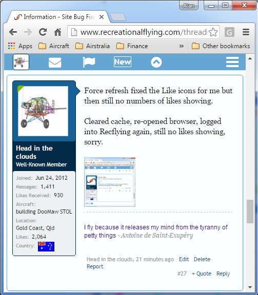
Force refresh fixed the Like icons for me but then still no numbers of likes showing. Cleared cache, re-opened browser, logged into Recflying again, still no likes showing, sorry.
-
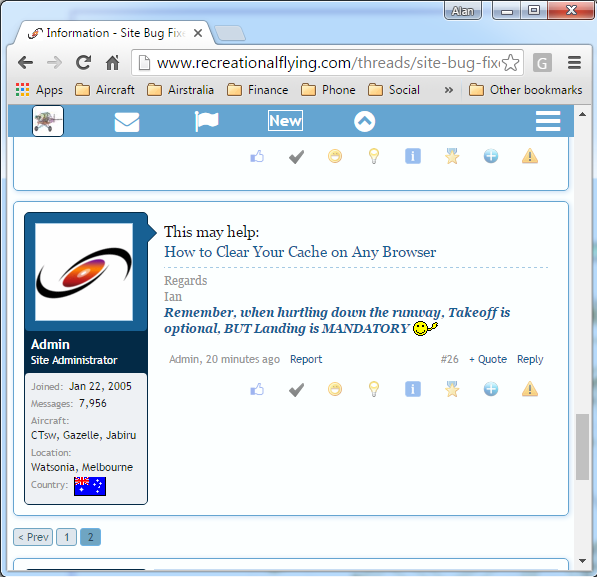
I don't see the number of likes either. Also - the Likes icons haven't changed although the pop-up ballon/description shows the likes themselves have changed i.e. the fourth icon is the spanner (instead of light bulb) and shows 'helpful', the seventh is the paintbrush and shows 'more' and the last is the rainbow and shows 'caution'. See attached, shows both issues - EDIT - Win7 Pro on Chrome
-
Yes, working OK now thanks. Wouldn't know how to send you a screenshot off a mobile device but probably not necessary anyway, only using this 'old device' until they replace my Note 7 when it's deemed not so likely to burst into flames at minor provocation.
-
On Galaxy Note 3 the hamburger goes to Home Page ...
-
I'd say so too. Might you consider that early TVs started out round? So round is actually a retro look, and then TVs/images went square and then 4:3 and now they're 16:9 and more .. boy that would suit the shape of aeroplane pics ...?
-
I couldn't agree more Ian. I don't think you'll get the majority providing individual comment on each of these new suggested changes, but we/they are likely to cast a vote.
-
FAA "dry" weight limit - incl removable battery?
Head in the clouds replied to trvlmscl's topic in Other Rec Aircraft
Good point but comparing cars and planes in this manner is a bit apples and oranges ... Potentially there's an absolutely immense benefit to be gained from series hybrid application in aircraft. The big thing about planes is that we're forced to cart around a big engine the whole time when it's only actually needed for a tiny percentage of the time i.e. for the take-off and initial climb. The rest of the time it's an inefficient heavy-weight gas-guzzler operating well below its best torque. The beauty of electric motors is that they can be run to whatever power setting you like (and rpm, within reason), provided you can get rid of the heat they generate. With modern liquid cooled brushless out-runners you can over-power the motors massively for a few minutes (overpowered to 3-5 times their continuous duty power rating) so you can have a nominally 30hp motor weighing very little but which can put out up to 150hp for the short period of the climb to cruise altitude. After which you reduce power to let the range extender recharge the batteries and the motor can then cool to continuous duty levels. Additionally - and here are the even bigger rubs - electric motors put out max torque at any rpm (even if stalled and therefore not turning) so they're the absolute best power unit for an aircraft. And ... they put out the same power at sea-level or 50,000ft so don't require any form of turbocharging for density altitude compensation, and ... they don't need constant speed or variable pitch props because by using a carefully designed scimitar style blade, under high power settings the sweep will result in sufficient pitch change to provide optimal pitch for climb and v.v. for cruise. Further - batteries actually increase their efficiency when heated to about 70-80C, so when you need the battery to have a higher power density i.e. deliver more power more quickly, you can heat the batteries using the waste heat from cooling the electric motor, which of course is producing more waste heat at that time so it's a win-win situation, which is rare among the usual compromises we have to endure in aviation. -
FAA "dry" weight limit - incl removable battery?
Head in the clouds replied to trvlmscl's topic in Other Rec Aircraft
This was the subject of extensive discussion on homebuiltairplanes.com, and while almost everyone felt that the only 'fair' thing was to consider the battery pack in an all-electric or series hybrid aircraft to be equivalent to fuel weight in an IC engine powered aircraft, and hence, for a FAR23 Pt103 'ultralight' the weight of the battery packs should not be included in the 254lb empty weight. However, that was nothing more than the 'wishes and dreams' of the discussion participants so the matter was referred to the FAA for a determination and they responded categorically that 'at this time' (it was about 2-3yrs ago) the battery weight would not be excluded from the 254lb empty weight limitation, not even to the extent of the allowable fuel weight for IC engine powered ultralights i.e. 5 US gallons. Several manufacturers, including the one referred to in the link above, indicated their intention to pursue the matter but there have not been any changes to the ruling to date, it would appear that the best/only way around it at present is by individual representation for exemption somewhat in the fashion that the ICON A5 has approached special exemptions to the weight limitations for USA LSAs. It's a real shame because it certainly puts electric Pt103 aircraft at a disadvantage compared to IC powered because the IC aircraft is weighed with an empty fuel tank and can then add the weight of 5US gallons whereas the electric aircraft has to be weighed with batteries on board and they weigh the same 'empty' or 'full'. I think the FAA fears originated from a lack of understanding, they may have thought that it would require hundredweights of (lead-acid) batteries to achieve similar electric flight times that 5 US gallons would provide in IC aircraft. They'd probably not heard of LiFePO4 cells, where 5US gallons' worth of weight in cells might provide an efficient aircraft with 20 mins or so of flight time. The logical thing would have been for FAA to find that the electric Pt103 aircraft could have an empty weight increase equivalent to the weight of 5US gallons of gas/petrol ... but no-one ever accused aviation authorities of suffering from an over-abundance of common-sense. -
DooMaw - building a STOL
Head in the clouds replied to Head in the clouds's topic in Aircraft Building and Design Discussion
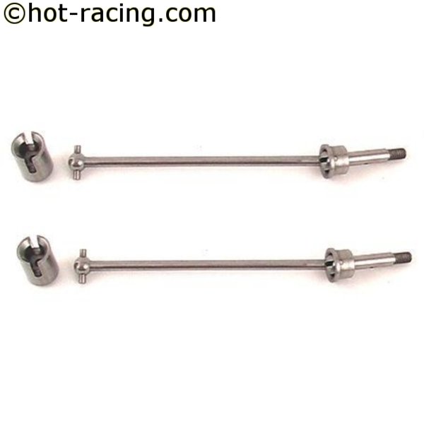
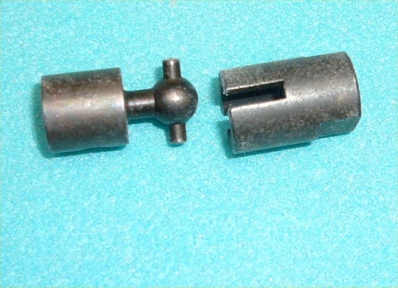
To bring the log right up to date ... I spent last weekend making parts. I think I'm down to fitting the last few bits to the fuselage frame then I can get the epoxy coat on. The timing has worked out well as far as the season and temperatures are concerned. I was rather optimistic four months ago when I bought the epoxy hoping to get it applied before the winter but at least now in our gorgeous Spring weather the temperature and humidity will be ideal. The coating is Jotun Jotacote 605 high-build high solids 2 pack epoxy which I have used before on steel and aluminium boats and it provides, in my mind, unrivalled adhesion and corrosion protection, and is extremely tough i.e. abrasion resistant and flexible, so it doesn't tend to wear off in high traffic areas or crack either. Like all epoxies it's prone to surface powdering/chalking if exposed to UV over long periods but the airframe is fabric and sheet-metal covered so that won't be an issue. Any areas that might be subject to constant exposure should/will be overcoated with a polyurethane coating. As far as the colour is concerned ... rather boring I'm afraid, I chose white. It's a little cheaper than the colours but that wasn't the reason. White shows up any defects better than colours. In event that you did get a weld crack or some epoxy coating damage, or corrosion under the coating for any reason, the associated rust will show up very quickly whereas on black, red or brown particularly, it takes a very close inspection to reveal any imperfections. Though I've learned a little about the coatings themselves, I'm far from being an expert on applying them, so if there are any folks out there knowledgeable about spray-application I'd be delighted to hear about tips and tricks. For the record I've bought a couple of new spray guns, really small gravity-fed HVLP ones with 0.5, 0.8 and 1 mm nozzles and 60cc and 100cc cups. I don't have a spray booth or any reasonable method of making one so I chose the tiny guns to be able to work closely on each tube and avoid as much overspray as possible. Back to the weekend of making parts - As described in my previous post, I had to work out the geometry for the aileron and flap connections, so I also made the templates for the bellcranks, control horns and the flap detente plate, marked them out on CRMO sheetmetal and started cutting them out and drilling them. Earlier in the week I'd been up to Brisbane for a meeting as part of my day job and for some unexplained reason I decided to take a diversion on the way home and return via my current favourite shop. I didn't have anything specific to buy, I just fancied a browse and I always get some inspiration when I have a look around that place. The shop is called Miniature Bearings Australia, and is an absolute Aladdin's Cave for modeller's, homebuilders and machine engineers. They stock everything from RC car and plane parts to bearings and linkages of every kind, small gearboxes, those bushings that you can't find anywhere, phosphor bronze rod (up to 3" diameter!) for making your own, balsa, carbon fibre, foam sheets, adhesives, wheels, ground silver steel shafting, keysteel of every size, you name it. (Click the link and just keep scrolling and scrolling down, you'll be amazed at their range of products that you just can't find anywhere else). They have a very efficient online shop too, for those unfortunate enough not to live nearby, and their online prices are less than their in-store prices, which more than makes up for the cost of the postage. Anyway, I digress yet again ... probably the only part of the DooMaw project I hadn't either worked out in CAD or had a good picture of it in my head, was the instant connect/disconnect method for the aileron and flap controls when the wings are folded or unfolded. It had to be foolproof i.e. must engage correctly and properly indexed without fail, and most importantly must not be 'sloppy'. I hate 'lost motion' (slack) in the control system, so the coupling method needed to be very precise without introducing tightness or stiffness, which I hate even more. Additionally, the coupling must permit a small amount of off-axis/angle drive, in this case it's the amount of the dihedral angle of the wings. So the coupling method was still playing on my subconscious but I was confident that the answer would present eventually. As it turned out the visit to Miniature Bearings was the catalyst. As soon as I saw the Dogbone Couplings used to transmit shaft drive in RC buggies and helicopters I realised I could adopt that method for the aileron and flap torque-tubes. A couple of pics shamelessly lifted from the net, thank you hot-racing.com and the other contributor - I worked out that I would need the ball part to be 7/8" (0.875"/22.23mm) diameter, to engage nicely with the 0.884" internal diameter of the CRMO end of the outboard torque-tubes i.e. with 0.009" (9 thou) clearance. The last time I did any ball-turning on my lathe was quite a while ago and I recalled that the set-up took me a day or two and to turn such small balls integral with the shafts would be fiddly and I'd need a fourth axis slider that I don't presently have. I quickly also gave up the idea of cutting or grinding them freehand to a profile template - if there'd been just one to do I would have, but four would take too long. Instead I decided to fabricate the dogbones from several parts and then spent a whole day searching the local bearing suppliers for self-aligning bearings and/or rod-ends that might have had pre-drilled balls of the right diameter. The local suppliers were hopeless - no stock, just catalogues - so I drove an hour each way to a supplier that I know has a good display stand of them. Vernier in hand I set about measuring their balls (so to speak) and was about to give up when I looked on the other stand and, amazingly, discovered that their Metric rod-ends had Imperial-sized balls and the Imperial rod-ends had Metric-sized balls. I decided that quite clearly ball size has nothing to do with regional origins ... Anyway I found that the 12mm rod-ends had 7/8" balls and that was all that mattered, I could make the cross-pins any size that suited the hole through the ball. $80 might seem a lot for four small balls but compared to the effort to make and drill them I saw it as a bargain. I cut one rod-end apart and got to work to make the rest of the parts. By the end of the weekend I have them all ready to anneal the balls and weld everything together. See the photo captions for more info - Aileron bellcrank and control horns being cut out - paper template and spray paint method to make the first, then scribe around it to make the rest Flap detente plate - a pin on the sideways-sprung flap lever will engage in any of the six medium sized holes arranged in an arc on the lower part of the plate, to select the six flap positions. The flap torque tube goes through a bronze bushing which will be installed in the almost-cut-out large hole at the top, which is the centre of the arc of the detente holes below. The smallest holes are to accept 1/8 rivets which will secure a PTFE/Teflon plate on the surface so that the detente pin doesn't make unpleasant scraping while changing flap positions. The top large hole wasn't completely cut through so that I can use the remaining 1/4" hole to align the plate with the outer holes in the same way as shown in the previous post for the aileron torque-tube. After the plate is installed I can complete the cut-out with the hole-saw in a hand-drill. The three larger holes serve two purposes, lightening of course, and also allow me to spray paint through them onto the cabin-top side plate which is very close outboard of it, I'll need similar holes in that plate to paint the back of this one. Second pic shows the bronze bushing to fit the top hole once it's fully cut out. The rod-ends, one has been cut to release the ball. Second and third pics shows the parts ready for welding to fabricate the dogbone. Bushings and torque-tube end fittings which will later be fitted to the inner ends of the aileron torque-tubes. Another 17hrs making a total of 1263hrs so far.
-
DooMaw - building a STOL
Head in the clouds replied to Head in the clouds's topic in Aircraft Building and Design Discussion
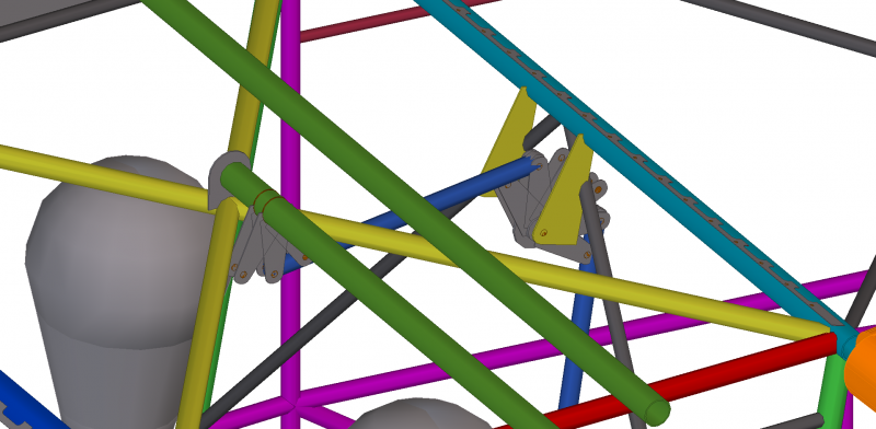
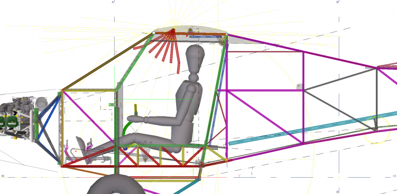
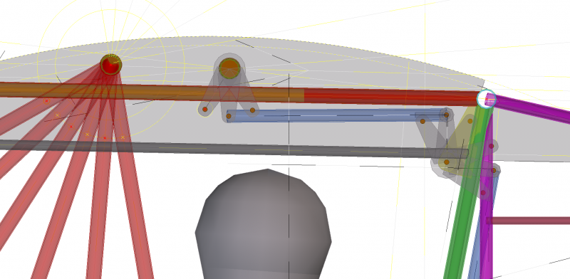
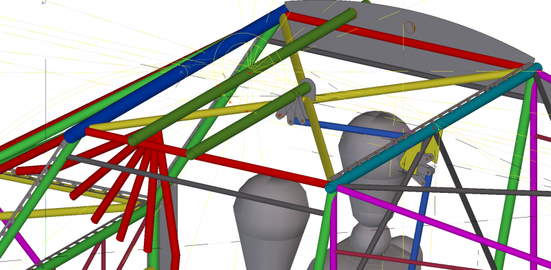
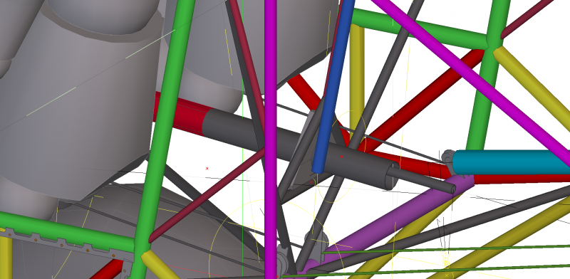
More log catch-up - between August 14th and Sept 2nd I was working on finishing off the list of remaining 'things to do' to complete the welding on the fuselage so that I can get the epoxy paint coat onto the frame and begin final assembly of all the parts. I wrote up the list in post #167 above, here it is again - Finish the tab plates Make and fit the throttle bar and supports Similar for the choke Make/fit hinges for the doors Make/fit latch plates for the doors Add cleats to secure the fuel tank(s) Fit the flanged cabin-top plates made previously to support the clear cabin roof Design/make/fit the cabin-top aileron control attachments Design/make/fit the flap control attachments ... and probably a few more things I haven't thought of yet. Some extra things I've thought of - plates to attach the gas struts to hold the doors open some tab plates with small holes in them, to be able to zip-tie wiring and cables so they don't flop around An attachment plate for a trim lever A plate to carry the headset sockets In my previous post I detailed making and fitting the throttle bar and choke cable bracket, then I went on and finished the last four tab plates which were two which hold the sides of the firewall and the two which hold the top of the windshield above the cabin. I then made the hinges for the doors and the baggage doors, they were larger versions of the control surface hinges i.e. small pieces of shaped key steel drilled off-centre in the lathe and welded in place. I decided against having plates for the door latches, instead the latch rods will locate onto mylar behind the door jambs which are already installed. I did install securing plates for the baggage door, at the front corners I added plates which will carry the spring for a Dzus fastener, and at the rear corners I drilled the harness bracket to carry a similar Dzus spring. The cleats to secure the fuel tank were added a while ago and described in post #168. Incidentally, DooMaw will have three fuel tanks, the main one forward of the instrument panel will hold approx 60 litres and will be fuelled via the lower starboard corner of the windshield, similar to a Wittman Tailwind, it's a good arrangement for a taildragger because it's the highest point of the tank. Having the filler through the windshield is one good reason to have a flat windshield if it's polycarbonate because being flat it's not under stress and so will not craze if (when) you inadvertently spill some fuel on it. The other two tanks will be wedge shaped, about 25 litres each, with one located each side of the elevator pushrod, under the baggage locker. They will straddle two of the lower fuselage cross-members and will be plumbed so they can be pumped up to the main tank as required. They'll also be easily removable so they can serve as portable jerrycans when fuel has to be obtained some distance from the landing ground. I had to go back to the CAD work for a while then, to design the aileron control linkages. I needed to transfer the lateral rotation of the control column's torque tube to create a longitudinal rotation of two aileron torque tubes above the centre of the cabin. I had to separate it into two torque tubes rotating in opposite directions to make the ailerons move opposite each other on each wing, of course. I also had to do that without having the pushrods where they would obstruct the baggage area or the occupants, and where they wouldn't be subject to accidental damage or fouling. To achieve that I would need two opposing pushrods running vertically close behind the seat frame to a pair of bellcranks at the top rear of the cabin. Those bellcranks to be supported by a pair of plates attached to the rear spar carry-through, and its associated bracing. From those bellcranks will be a pair of pushrods running forward along the cabin top, above and between the occupants' heads, which attach to control horns on the underside of a pair of opposing torque-tubes, one of which will operate each aileron. It was a tight fit to get it all in with enough angular motion available for the bellcranks and the control horns because in each case they run past/through bracing structure which limits the motion, thank goodness for CAD, it would be much more difficult without it. Here are a couple of CAD images which show the extent of the motions available. I'm getting 30 degrees each side of centre which is ideal to avoid too much Ackerman effect at this stage, instead it will be employed at the outboard actuation to achieve the differential between the ailerons' up and down travel angles. The blue pushrods operate the ailerons - I've only shown the port set, the starboard ones are a mirror image. The red is the flap handle, showing its range of motion, 0-60 degrees in 5 stages - Next I fitted the flanged sheetmetal each side of the cabin top at the wing junction, they carry the edges of the windshield over the top of the cabin, give support to the small tubes which carry the door and baggage door hinges, and also carry the bushings to support the centre sections of the aileron and flap torque-tubes. I then went on and marked out the positions of the centre of those torque-tubes and drilled a 1/4" hole through which I could thread a 1/4" rod to hold the aileron torque-tubes' centre support in place (above the centre of the cabin top) while I tacked it in place. That process ensured everything was in perfect alignment, which it needs to be if the controls are to work smoothly and also connect and disconnect automatically when the wings are folded and unfolded. I ordered the door gas struts online. The last ones I ordered, which were a similar size (300mm long when extended) to support a large toolbox lid, were over $100 each about 20yrs ago and lasted about six months. They're amazingly cheap these days, $23 for the pair, delivered by courier the next day, and with a 2yr warranty. Once I had them in hand I could estimate a range where they'll be fitted, so I made plates with a sequence of holes to allow for adjustment. I'm happy to have the extra holes anyway, because they're in the hat-rack baggage area and so will be useful for securing a cargo net or similar - in my book you can't have too many tie-down/attachment points. And that was the state of play about ten days ago, some pictures - There's another 44hrs in that lot, which makes 1246hrs so far.
-
DooMaw - building a STOL
Head in the clouds replied to Head in the clouds's topic in Aircraft Building and Design Discussion
For some while there have only been oddments happening so there's not been a lot to write up in the log so it's time for a bit of a catch-up - Between July 19th and August 13th I was working on the throttle mechanism and the plate for the engine control cables. Unlike most two seat aircraft DooMaw will not be restricted to a single primary control seat i.e. both seats will have primary controls so that it can be flown solo from either seat. Usually that is not permitted because the second set of controls 'slave' off the primary set, hence any failure in the slave linkages would render the aircraft uncontrollable if flying solo from the second seat. The other requirement for two primary control seats is that any controls that are not duplicated must be operable from the second seat without undue difficulty i.e. must be accessible with the seat harness correctly fitted and adjusted, and must be operable while also being able to operate whichever other controls must be handled at the same time - changing hands on one or other is acceptable. Also, if flying from either seat it means that all instruments must be visible from both seats, which in DooMaw's case they are, albeit that they will be more conveniently and conventionally arranged when viewed from the left seat. For safe and effective take-off and landing management I wanted to duplicate the throttle lever for both seats so that the control column can be held in one hand and the throttle operated by the other without having to change hands at all. With a little experimentation I found that a single operating lever for the flaps would be acceptable, although better STOL operations would be managed from the left seat. The other non-duplicated controls would be the choke, carby heat, cabin heat, throttle friction and comms. Comms will be on the panel and reached easily enough from both sides. Although I do want the facility available - to be able to fly it from either seat - it's still likely to be usually flown the left, so the other controls (choke, carby heat, cabin heat, throttle friction) will be placed for most convenient operation from the left and within reasonable reach from the right. Finding a good location for a bracket to carry the three cables (choke, carby heat, cabin heat) proved more difficult than expected. I couldn't have them anywhere on the panel or on a forward centre console because although they are bowden-style cables they are solid core (not multi-strand cable) and the first 120mm or so from the control knob is quite rigid, so the cable run must extend straight forward for some way ... and the main fuel tank is located forward of the panel, so that rules out anything in that location that extends forward more than the depth of the instruments. Also - I need some structure forward of the cable mounting point to have a small bracket with a hole in it to cable-tie the cables onto, so that they don't flop around. The only suitable location proved to be on the left fuselage side below the panel near the pilot's left knee. In line with the crashworthiness objectives of the design this meant careful consideration of the shape of the bracket because the obvious rectangular shape would produce a serious hazard to the knee in event of a forward impact. Tapering the bracket off at the bottom, giving it absolute minimum projection out from the side (just wide enough to fit the flanged nut on behind), a folded outer edge and a rounded lower corner has made it reasonably unobtrusive. Similarly, the throttle proved a little trickier than I originally intended. I was going to have a throttle bar running behind the underside of the instrument panel, with throttle levers each side curving down under the lower edge of the panel and then upward, like the Lightwing arrangement. For several reasons - one of them again being the fuel tank location - that didn't prove suitable. The next-favoured spot just in front of the forward seat support, under the knees, was convenient to locate it and provided a natural position for the hand, but is an area that is very convenient for putting 'things' like sunglasses, water bottle etc and that meant it was subject to fouling the throttle one day. So I decided to keep that area available for those 'things', in fact I'll probably make a small locker there each side so that it can be used with confidence that loose items won't escape into any of the controls. Which brought back memories of the mayhem caused to some station pilots during feral control in early days R22s. Before the pedals were fitted with rubber boots over the slots in the floor, ejected cartridge casings would regularly fall down the holes and if you were unlucky they'd jam the pedals which made for interesting landings sometimes ... The result was that I decided to install the throttle torque tube behind the forward seat support i.e. under the front of the seat, and that meant to be able to install it and to remove it for servicing it would need to be made in two halves that bolted together. Also - one of my pet hates is throttles that 'creep'. With carbys sprung to wide open it often means that when idling the throttle may slowly advance on its own which I find annoying, and I also like to be able to secure the throttle quite firmly so that a passenger is less likely to bump it open at an inopportune moment. I don't like throttle locks because you can't over-ride them in an emergency, so it had to be an effective and adjustable friction device. I've fitted throttle frictions before, made from plastics, and they haven't been as effective as I would have liked, so this time I decided to bear the slight weight penalty and make it from solid brass. I could machine it far more precisely and the metal wouldn't conform to a new shape in the same way that plastics do when constantly under clamping loads. A PVC plastic friction device from an earlier project - I used split blocks bored through the split line with the bottom of the blocks bolted together with a o.1mm shim between them and the top of the front block is clearance drilled and the rear block has an M4 tapped thread. In the forward support tube is a compression spring which holds the blocks apart when the knob is turned left, and a half turn adjusts the friction from zero to very firm or anything in between. For the throttle torque tube, one of the trickier parts of making bolted flanges on the ends of two pieces of tubing is getting them exactly square so that when the two tubes are bolted together they end up straight. The problem is that even if you jig them straight at first, the welding often pulls them around a bit and they don't end up that way. This time I set them up on the tube and welded them in place before cutting the tube in half. It worked well, the pictures tell the story. The final parts of the throttle mechanism were making and fitting the throttle levers, the clevis plate for the cable inner, the socket which supports the cable outer, the adjustable throttle stop and non-adjustable one on the other side, the bearing plates which support each end of the torque tube and the support plate which holds the friction device in place. It's certainly a lot more work to make dual side-by-side throttles than a single throttle or even tandem ones where the rear one just has a link rod to make it mimic the forward one. By the way, a couple of people have asked why I'm using thin plain nuts instead of nylocs. They're only temporary at this stage, and because they need to be assembled and disassembled many times during the build, they're much quicker than nylocs, which should only be used once in any case. All the bolts and nuts will be replaced with new AN bolts and nylocs or castellated/pinned nuts, or clevis pins, during the final assembly. Another 43 hours for the log, 1202 hours so far.
-
Dyn Aero canopy open in flight
Head in the clouds replied to fly_tornado's topic in Aircraft Incidents and Accidents
Something I've noticed is how very different we all are in regard of our attention to basic matters of safety. People have called me paranoid because the last thing I do before boarding is a final walk around. It allows me to notice anything I might have forgotten, and which I can't fix from within the cabin. I have a similar 'hatches, harnesses, T&Ps and Outside', discipline which I cannot make myself ignore prior to taxiing. Boring, I readily admit, but it's a regimen that has served me well. What surprises me is how frequently I see people jump in and take off and if anyone's ever cheeky enough to broach the subject it's very robustly pointed out that checks had been done before the first flight of the day. How can you argue with that ...? Those who have chosen to laugh at my 'paranoia' have mainly been those who had previously left off a fuel cap, took off with the other door unlatched, pitot covers still in place or similar - and the best was the young, new and invincible commercial pilot who had to return on a charter flight departure because he was dangling the tie-down chains! The point being ... that if you don't have a personal culture of carefully checking everything and assuring yourself that all is well, then no amount of warning lights or alarms will always save you. The best relevant example I know of is that which I have posted here a few times - the fella who landed a Trinidad or Tobago in a valley with wheels up though proximity warnings were blaring for a long while beforehand.


.JPG.6c761ace69dc90babf175261fb97df44.JPG)
.JPG.e7d23d85408616849bf8336085d11df0.JPG)
.JPG.716c7458c95f6bc8aff76a3cabae1969.JPG)
.JPG.edd9e2c74f05e6c9eb3b9e57de7817e6.JPG)
.JPG.a306c624134d15aae3e2ef5057296cb7.JPG)
.JPG.c8aeb3749ce414ac06800ff3ec27d2b5.JPG)
.JPG.562303784d4ccd723ca8e0d1a6333eb9.JPG)
.JPG.af254300b5ed871a7e9295d59349be01.JPG)
.JPG.066a0fc9910c386877b1cc708ecee2c5.JPG)

.JPG.5db44a10557aadd382ccafb8924cfaf4.JPG)
.JPG.fa74c071b01c574a85587a4c665b64c1.JPG)
.JPG.52e64cb4b834e4febe13d6e10f1e0b70.JPG)
.JPG.d1b17d0e700f80a60f5f3bfd0d4e4742.JPG)
.JPG.37ecfbf3f33427bee71d408f727853d7.JPG)
.JPG.d6189abd62c618b8f124420763a0d7ee.JPG)
.JPG.a53ff4d635869d472695ca0cfaacd8d6.JPG)
.JPG.006800318675f2f6dff6c9a5d85553b2.JPG)
.JPG.e3ce46c2ad8acc4b48a61c05c3884ca6.JPG)
.JPG.1f6be3873f9879f75768522d17cb6fcf.JPG)
.JPG.08752887719e6e29206ef52172723f82.JPG)
.JPG.0987e7d713c522112ae95519c8830da7.JPG)
.JPG.582aa4c8bb1b698eaabe3f903c2185d0.JPG)
.JPG.6676ea4ca02cc890ff6088b293b191e4.JPG)
.JPG.c8626ec6de266356fa2851e40ef5847e.JPG)
.JPG.56705fcdbee1ae7b361083d1e0a0525a.JPG)
.JPG.8abab033e05350fc79ed80cf05c5a959.JPG)
.JPG.4da8ab2e0a7c84105973c4f276da10c8.JPG)
.JPG.fed2ce723fa68246a3c8ab674f6d23b3.JPG)
.JPG.8b7dd6059896da00c2c65e710c5177a3.JPG)
.JPG.e7824fbc7c93cfc2a0e5418b497fb605.JPG)
.JPG.3230a4095f0a2dcbbdcc73cb1a74a038.JPG)
.JPG.c26b1b335869019fac7320602fe283fe.JPG)
.JPG.b2a0792ee4821c265fb79e5e11bb6db9.JPG)
.JPG.5b0f2334f3bcbf5fb7db2c4f7270a72a.JPG)
.JPG.93b844706a5effaefb61a77cab9b9d34.JPG)
.JPG.f9ca7766c4d5a0ef3239bbf046a0fc16.JPG)
.JPG.e19696c611b869db855f00b26f3a9cc8.JPG)
.JPG.807803b868d5f6a5db437f7cdfc7e018.JPG)
.JPG.834a1f405a10b2fa625d554af7fcf243.JPG)
.JPG.705b5e6cfe74357f9eea09e93a54903b.JPG)
.JPG.736adc71b2e1c0cc4169ac24eb8d5fbc.JPG)
.JPG.6ede552a020d2805b6621164de4b39d1.JPG)
.JPG.bbb9a4963d34af5cdbd5cb5968efcef6.JPG)
.JPG.c1bb91a411cd197690bcbf36ef34b2fe.JPG)
.JPG.98ff87aac354ca879111330da6380988.JPG)
.JPG.c28ff3067ad1520d1dfeee71394f42ba.JPG)
.JPG.ff2034db9b1b66c49ba0c91d6bcf6d15.JPG)
.JPG.5e98d313ac616978abf4ef3ca02f22bf.JPG)
.JPG.4c01f6ccd3871ff8e9917dc902827d28.JPG)
.JPG.5f436ce22af82a027170935d22bf2124.JPG)
.JPG.401c1369cbb542b9390933fb0aff38e2.JPG)
.JPG.7fa9531539985feebba10e48b627488c.JPG)
.JPG.bb7330e1e69ec3193218501e12842a83.JPG)
.JPG.b7a5a2d6b648686c7835f45e3f96e484.JPG)
.JPG.c86eabe355e238105fceed01779af1f9.JPG)
.JPG.a7bc75964c6ca765d2f7774ce0b68126.JPG)
.JPG.ff1b79fb75eb1b63a359ae3dc71fc606.JPG)
.JPG.df82f2627910d446f84a6e9bc38641c7.JPG)
.JPG.f56999537e79d4188450d32d18b75c06.JPG)
.JPG.088c0d24bd115776e5e27f937b51b0ff.JPG)
