
Head in the clouds
-
Posts
1,842 -
Joined
-
Last visited
-
Days Won
42
Content Type
Profiles
Forums
Gallery
Downloads
Blogs
Events
Store
Aircraft
Resources
Tutorials
Articles
Classifieds
Movies
Books
Community Map
Quizzes
Videos Directory
Everything posted by Head in the clouds
-
Quaich SSDR
Head in the clouds replied to SGIAN DUBH's topic in Aircraft Building and Design Discussion
It depends what you call credentials, I don't have formal aeronautical engineering qualifications however I have been studying the subject since 1976 during which time I have completed fifteen aircraft, not completed two others and am nearing the completion of the current one (DooMaw, my avatar). The completed ones were all successful and fly well, the varying experiences I had with 'tuning' some of the earlier ones, and abandoning two of them are all testament to the learning curve. All are/were of my own design. Experience of that kind, and over four decades, does provide valuable real-world experience that some might say amount to a little more than 'well meaning findings', but by all means take my observations as you see fit and do with them as you will ... :-) I didn't say the Quaich's stall speed would be much above the 30-40kt region, I said the tail control surfaces looked like you might have a minimum controllable speed well above the stall speed. I said the elevator wasn't likely to have enough authority to bring the mainplane to the stall. That results in the minimum controllable speed being well above the stall speed because when you reach full rear stick travel the lift and moment provided by the elevator isn't sufficient to overcome the moments provided by the CG being ahead of the Centre of Pressure (CP), the pitching moment of the airfoil and any additional pitching moment provided by extending flaps. It all adds up to a plane that won't fly as slow as it could, if you could bring it to the stall. It's a much misunderstood thing, people bring the stick back to the stop, the plane gets slower until eventually it reaches a minimum flying speed and 'mushes'. How often have you heard people say their plane is very kindly in the stall, it just mushes? Fact is, it hasn't reached the stall at all. Now, that doesn't mean the assurance you were given that "the Elevator has more than enough authority to ensure a controlled landing" is wrong, it means that the landing will need to be much faster than you expect, because if my assessment of the elevator's size is correct, then you'll run out of elevator authority way above the stall speed. And - earlier, in the Sgian Dubh thread, you said you had an aerodynamicist who was "the most respected aircraft engineer in UK" or words very close to that, involved in this program. Above you said "Until it gets test-flown ( in the air ) it will be an unknown stall speed". That is a mystery ... how can you have such a highly revered person on the team and he doesn't seem to know how to do the most basic of aeronautical calcs i.e. the stall speed prediction. Presumably you know the airfoil section, the wing area and the weight of the aircraft? That, and a set of polars for the section (available on many sites online) are all you need to predict the stall speed with great accuracy. Determination of similar for the HS, factored by the tail moment, would tell you for certain whether the elevator will have the authority to fully stall the mainplane or not ... it's basic stuff. Assurances are good - but the proof will be in the pudding, as they say, and the actual fact will be very easy to find out as soon as you start taxi tests, so the tail-lift thing is a non-issue - you'll know the answer before you ever need to get airborne. If the one providing the assurances has conducted a lift coefficient and moment calc for the HS and VS then it would be useful to attach it here, if you like. Second opinions would likely be forthcoming and where controllability and test-flying is concerned it doesn't hurt to have a few of them. Just my opinion again - but a well maintained 2T with a knowledgeable operator can be very reliable. In my experiences the key issues are - maintain full throttle in the climb, a lot of folks like to 'back off a little' and that leans the mixture considerably which makes it run a lot hotter and risks nipping up. Make sure you don't have air leaks in the induction, either at the rubber mounts after the carbies or direct to the crankcase (via the fuel-pump pulse line is a classic), they both lean the mixture with disastrous results. Avoid low idle speeds on the ground, the 'rattle' breaks the crankshafts. Avoid long low throttle descents, it shock-cools them and that can crack things, or they can oil up the plugs and stop, or oil-injected ones can run with insufficient oil in the mix. Use 2T oil for air-cooled 2T engines, not for water-cooled engines like outboard engines, the oil is designed to burn at different temperatures i.e. air-cooled engines run hotter so oil for water-cooled engines burns too soon if used in air-cooled engines. HIH. I didn't say the forward position of the mainwheels was 'dangerously tricky', and neither did I mean that it need be any kind of problem. What I was on about was that it would have two effects - first it would make the weight on the tailwheel greater than if those wheels were further aft, consequently the 'down' elevator has more work to do to lift the tail in the take-off run, and secondly the further the wheels are ahead of the CG, the more work the rudder has to do in a crosswind. In both cases the forward wheels position does a dis-service to the already very marginal tail flying surfaces' effectiveness. -
Quaich SSDR
Head in the clouds replied to SGIAN DUBH's topic in Aircraft Building and Design Discussion
A couple of observations that you might want to consider during your testing - 1. If it was mine the elevator and rudder would have much more area. The area they have at the moment is more typical of an aircraft with a stall speed in the vicinity of 60kt than the 35-40kt I imagine this will have. Consequently it's very likely that the elevator will run out of authority a fair while before it could bring the mainplane to the critical angle and stall it, so you may find your landings will be a good bit faster than anticipated, or is desirable. Similarly the elevator may not have sufficient authority to lift the tail during the take-off roll. If the aircraft has flaps and you use them on take-off then they would move the centre of pressure of the mainplane aft and that would help with the situation very considerably. If you don't have flaps, or don't use them for take-off, and if the engine has sufficient power to overcome the drag and reach take-off speed in the three-point attitude (with a 447 it should have) then you would be likely to become airborne in the almost-stalled attitude. Once the wheels are off then you'd want to lower the nose and build speed rather promptly or risk a wing-drop (lowering the nose would happen 'automatically' if you maintain stick forward as it lifts off, of course, though that's not entirely intuitive) ... this situation of perhaps not being able to lift the tail prior to take-off is made worse by the position of the mainwheels which appears to be a little forward of the leading edge (in level flight attitude) - right below the leading edge is more 'usual'. The condition would be improved by ensuring a CG toward the forward end of the range but that could be a bad trade-off in terms of increasing the landing speed even further because of running out of 'up' elevator authority even earlier. 2. It has a tall rudder, and some of its area below the HS, which is very good, but I'd venture to say that you might find it has rather limited capability in cross-winds. The large amount of fuselage side-area behind the CG, the forward landing gear position and the smallish (narrow chord/high aspect ratio which stalls at a lower Reynolds number than a lower aspect ratio would) rudder all combine to limit the aircraft's cross-wind ability, so I'd be leading up to cross-wind landings gradually. -
The XPB Stage 1 underway.
Head in the clouds replied to bexrbetter's topic in Aircraft Building and Design Discussion
I'd be mighty surprised if a sample of Australian smelted aluminium alloy turned out to be anything other than it was claimed to be. Australia and Canada have the highest QA standards and consequently the best reputations in the world for the consistency of their alloy production. It's a jealously protected reputation too, because it has resulted in these countries now being the preferred alloy supplier worldwide in the shipbuilding and transport industry. For major marine projects same-batch billet material is used for the framing and the plating and is also sent to Italy (usually) for the production of the welding wire, to ensure a perfect match of alloy throughout, and hence prevent electrolytic corrosion. The sample you bought in Australia might not have been Australian made alloy, even though it could possibly have been extruded here. A lot of billet material is imported, though any extruder would know if a different alloy had been substituted due to its different extruding/plastic temperature and properties. Another possibility is that the sample you bought was neither smelted nor extruded here, the majority of extrusions and rolled sheet material sold here are imported these days. Capral is one of the few remaining 'High Street' stores that stock material of Australian origin. If my information is still current Ullrich also extrudes some Australian billet down Sydney/Newcastle way but I think all other suppliers import their entire stock and mostly from ... you guessed it, China. Much of the Chinese smelted alloy started life as Australian Bauxite mined in Nhulunbuy on Gove peninsular and Weipa on Cape York peninsular. 6060 (usually found in T5 condition) isn't a 'bit' weaker than 6061T6 it's closer to half the tensile strength at 160MPa compared with 260MPa for 6061, one wouldn't want to design for one and end up using the other by mistake, in any industry. So a company 'passing off' 6060 as 6061 wouldn't stay in business very long. -
GA must refuel from sealed drums?
Head in the clouds replied to rdarby's topic in AUS/NZ General Discussion
Who told you that? There'd be a hell of a lot of grounded and abandoned planes in the bush if that was the case. The vast majority of the refuelling I did in the bush was from partially full drums or drums refilled at the nearest airport which was often hundreds of kilometres away. And I'd never have reached most of my destinations in helicopters if it wasn't for refuelling them from Jerrycans. I haven't read the CARs relating to fuelling for a long while but they used (when they were ANRs) to provide plenty of detail of the procedure for fuelling from drums and jerries, hot-refuelling etc. I'd expect it's still there, I'll have a look when I have some spare time, meantime ask whoever told you for a reference to the legislation covering this. It's my guess that they don't know what they're on about ... All that said, it's important to check the fuel carefully, whether it's in a sealed drum or not. Sealed drums don't guarantee anything, I used to have sealed drums delivered from Darwin to our heliports in the Kimberley. We had several cases of Avtur contaminated with bacteria that would clog the fuel filters in minutes if you didn't detect it before putting it in the tanks, and one case of Avgas mislabelled as Avtur, and two cases of whole shipments of correctly labelled Avgas delivered instead of Avtur. So it certainly pays to be vigilant about your fuelling. -
I've flown a Trinidad but can't recall whether the alarms are wired to the intercom or not. What I do recall is that they're a very quiet aircraft and there wouldn't be any problem hearing the alarms even if they're not, and especially when the engine power is pulled back for approach and landing. Also - when the alarm starts warbling, the lower tone is the stall-warning so whatever the arrangement the aircraft would be configured so that the pilot could hear the warnings when they sounded. There's a third kind of pilot who flies retracts, it's the kind who've been given a sufficiently sobering scare to always do their checks in future. Mine was deliberately set up for me by my instructor in cahoots with the Tower at Coolangatta during the last stages of my training. My instructor was former RAAF and a real stickler for procedures. He felt I was doing my checks too much by rote so without my knowing it he had a chat with the duty controller and asked him to make me super-busy during my next circuits. I was on short final and was asked to expedite as a 767 was on long final behind me. Nearly at the piano keys I was told to go around as there wasn't enough clearance for the heavy. I cleaned up and went around and was on late downwind again when I was given a runway direction change, I cleaned up again and went around for the opposing downwind, by this time I had a mild sweat running and my radio work wasn't quite as polished as I'd have liked ... at mid-downwind the instructor keyed the mic twice which I later discovered was a cue for the controller to interrupt my checks. He asked me if I could see the traffic ahead and also behind me. There wasn't any traffic but it had my head on a rapid swivel until the instructor pointed out that I was late turning Base and he asked me to do a flapless approach this time. Between them they kept up the pressure until, on very short final I heard a just-audible whisper which said "Pilots who don't do their checks will one day land with their gear UP". It didn't sink in for quite a while and we were close to touching down when the instructor began to lower the flaps which kept us in the air long enough for me to realise what I'd done, or rather not done, and firewall the throttle. I've been fairly insistent about my checks since that day, as you might imagine.
-
Well that's a bit of a relief, however I was only quoting you verbatim - you said "But at least with a radio, you know someone is nearby and you can start to look for them" (the bold is mine). However, there are a couple of things folks who depend so much on their radios to alert them to the proximity of other flyers, should keep in mind. The first is something I've kept in mind since the days when I was instructing. Having taught the students all their nice radio protocol they would, for example, line up and announce their pending take-off, and from that moment they would be quite confident that anyone nearby was fully aware of what they were now embarked upon. They never gave a thought to the possibility that there might be someone quite close by who was distracted for a moment and didn't listen properly and understand what they heard. Nor any account given to the possibility that their transmission might be shielded by a hill or that their radio wasn't transmitting strongly or clearly for whatever reason (faulty microphones are the most common reason BTW). So beware of this trap folks, just because you transmitted your intentions, it doesn't mean anyone, or everyone, heard and understood what you said. And even if they did, it doesn't mean they correctly interpreted it. Secondly - do you keep in mind that people under pressure go deaf? Someone arriving at a busy gathering for the first time, like Narromine for example, is very likely to be feeling the effects of pressure and some uncertainty. It's well documented and taught in GA CPL Avmed courses that people lose their ability to hear and/or comprehend as their stress level and/or workload increases. One of the best examples I've seen is an onboard video where a fella is landing with 3PoB on a valley strip in the mountains at Megeve, France. He's flying a retractable Trinidad or Tobago and the gear-up warning siren starts as he turns Final. It's sounding loudly the whole of Final and he doesn't hear it at all even when it starts warbling as he rounds out and he continues and lands on the belly - quite a sobering thought if you're relying on hearing your radio, or other people hearing it ...
-
And that's the crux of the problem. See and Avoid is the basis of VFR flight, which means you should be scanning constantly, not start looking when you hear a transmission. Otherwise you're not allowing for radio failure (yours or theirs) or people failing to transmit when they should, or aircraft not required to be radio equipped, or certain radio - silent military flights announced by NOTAM only, or drones, pelicans, weather balloons, ferris wheels ... to mention just a few
-
DooMaw - building a STOL
Head in the clouds replied to Head in the clouds's topic in Aircraft Building and Design Discussion
That's fair comment but it all depends on how you address the situation. Knowing that road loads are hard on the airframe means you have to provide adequate support for the wings. If you're not going to remove them, the first part is to secure the folded wings to the aft fuselage to take the load off the strut attachment and wing root attachment points. The next part is to support the fuselage, or partially support it, to reduce the loads on the landing gear. In my case, and any bush plane, the main gear can easily withstand the road loads and the big soft tyres and long-travel suspension help to damp the shocks to the airframe. However it's a different matter for the tailwheel when the wings are folded because the wings then add a lot of extra weight on the tailwheel, so in the trailer the aft fuselage need to sit in a shock-absorbing cradle. The last part of it is the suspension under the trailer. If you're towing any aircraft you need to use airbag suspension not steel springs, this has been shown to be sufficiently soft-riding to even transport helicopters on their skids, and with blades attached, albeit with supports at 2/3 span. The trailer is often the culprit when damage is sustained to a towed aircraft. It pays to build the trailer heavy, though there is a tendency among people to build them light because they're carrying a large but lightweight load. A heavy trailer with airbags absorbs a lot of the shock rather than transmitting it through to the airframe. Anyone who has fired both a lightweight shotgun and a heavyweight one will know what I mean ... Your comment is perfectly valid though, if you don't take the extra measures to protect the airframe. Just securing a plane sitting on its landing gear with folded wings supported by the struts, in a steel-spring suspended trailer and towing it on even a relatively smooth bitumen road is likely to end in tears, let alone the damage that would be done if you towed it on a rough surface. In my mind the best way to transport an aircraft, if at all possible, is to fly it of course. Yes, not expensive either, $50 + $10 postage, cheaper than my manual swager was. It's a twelve tonne press and the dies are 10mm wide. The swager the stainless wire rope company uses commercially ($2 per swaging operation plus the cost of the swage) is a 30 tonne press and their dies are 25mm wide so I figure the compressive force/area is similar. As you can see in the above picture I applied the press twice, I know you don't do that with Nicopress and similar sleeves but with these long rope-end sleeves it seems like a better solution than one pressing in the middle - thoughts on that? Heavy Duty Hydraulic Swaging Tool As purchased it comes with eight different-sized sets of swaging dies but they're only suitable for copper or aly swages. In the text they mention that if you want to swage the stainless ends like I showed in the image above, then you need to buy the hardened die sets. They have two pairs which are the right sizes for 1/8 and 3/32 cable swages and they charged $10 for the two sets. And setting the stainless swages takes a fair bit of effort so you grow muscles at the same time - Bargain! -
DooMaw - building a STOL
Head in the clouds replied to Head in the clouds's topic in Aircraft Building and Design Discussion
29th May 2016 After completing the strut attachment points I posted about previously, I fitted a small bracket to the top of the aft fuselage to carry the VHF antenna and then made and welded in the harness attachment points. I forgot to take photos of them so I'll post them next time. Pylon500's comment about the length of the elevator pushrod had been gnawing away at me in the background so checked my buckling calcs and it still came out fine but when I was wheeling the fuselage to the workshop over the gravel driveway the push-rod had a very noticeable bounce in it that just doesn't look good. Oscar very generously had sent me some Purathane material to make a grommet to support the tube mid-span but that would still mean it would flex and any contact with the grommet would cause some wear and it's a very thin-walled aly tube (0.035"/0.9mm). The amount of work required to make the grommet and its support would have been as much, if not more, than the work to add another walking beam and divide the long pushrod into two. I was a little miffed at myself for having to do that at this late stage, and particularly because the two ends of the pushrod that attach to the walking beam would be attached in tandem and the Ackerman Effect would slightly change the elevator geometry, affecting the up and down ratios. Then I realised I could place the two rod-ends beside each other rather than in tandem and not have a geometry change. At first it appeared that doing that would introduce a bending moment in the pushrods but it isn't actually the case, all of the bending is resolved in the bolt and cleats that hold the pushrods to the walking beam. Problem solved, so I machined up the new pair of large pushrod ends, and made the walking beam and attached its hinges to the lower fuselage between the rudder cable-guides. Photo of it installed next time but here's the walking beam frame - Next I made up a couple of flanged plates to go above the cabin and secure the clear polycarbonate sheeting that forms the cabin roof. I used a tool that I'd made a couple of years ago for another project. It's a pair of ballraces mounted on socket head cap screws that I'd machined eccentric so that by turning the screws the rollers move closer or further apart and can be adjusted to roll different sheet thicknesses. Ahead of, and behind the two horizontal rollers are two small diameter tube rollers also on ball-bearings, that are set a little lower than the bottom of the horizontal rollers. There is one more roller, vertical, between the two main rollers. By feeding the sheet vertically into the slot between the main rollers and keeping its edge on the approach side feed roller the sheet bears down firmly on the fifth, central roller, allowing you to put sideways pressure on the sheet and roll a flange along its edge. The edge can be curved or straight and due to the limiting roller between the main rollers, the flange is always the width of the horizontal bearings - 12mm in this case. I then used crimping pliers to remove the excess material which was due to the curved edge and the stretching during rolling, to leave a flat flange. Life got in the way for the next four weeks with an overseas trip, re-springing a couch, fitting curtains, building a built-in robe, a birthday BBQ for my wife and my drafting work got busy too so it was a hectic time and I haven't touched the plane until this weekend. By then I'd lost all momentum and it was a case of staring at it for a while to decide what to do next. Somewhere among the above other projects I'd managed to order some quality 316 steel rigging cable, a hydraulic swaging tool and a bunch of wire balustrading hardware to assess for suitability. The first test was to get a couple of friends and the three of us bounced around on some balustrading that had been installed on a job I'd drafted a couple of months ago. It stood up to it surprisingly well, nothing broke though we did stretch the wire. I went to the stainless company and was let loose on their test-rig for an hour and came back well informed, the balustrading hardware will easily carry the loads for my tailplane bracing. I'll be test loading it later in any case ... The stainless swaged ends for the cables are as light as they could be and still do the job, and having threaded ends they can be used to do the cable tensioning. I didn't want to use the bottle-screws as they were, they'd be too bulky, so I cut them in half - which gave me the left-hand and right-hand threads I'd need for the tensioning. I could have done the same with ordinary left and right nuts but I wanted more (longer) thread and the bottle-screws have 11mm of thread internally. So making up the cleats and welding them in took up the rest of the weekend. Back to work again tomorrow, ho hum ... Another 38hrs for the log, 1072hrs so far.
-
I can't advise you to do one thing or another, this being such a ridiculously litigious world these days, but I can tell you that people (myself included) who used to operate planes and helicopters in the remoter parts of the country didn't always have the luxury of getting mechanical problems fixed as soon as they came about. Consequently we would often have to fly for days or weeks with oil leaks and it all came down to assessing whether the leak was going to get bad enough to lose a critical amount of oil during the next flight. The only sorts of things that would cause that to happen would be cracked crankcases or oil drain plugs with stripped threads, for examples. An oil filter with the O ring damaged could do that too. Otherwise, things like tappet/rocker cover gasket leaks just had to wait until the next 100 hourly service . On some engine types you could nip up the rocker cover bolts a bit and stop the leak altogether, other types, like VW engines, have a spring clamp which can't be adjusted, so replacing the gasket is the only option, but I did have a VW beetle with rocker cover gaskets that leaked quite copiously for a year or so before I did anything about it. Not to say it couldn't happen but I've never seen a rocker cover gasket leak on a car engine or a plane that became suddenly drastic, usually the leak just gets very gradually worse until you get sick of the mess and replace the gasket. EDIT - to send a PM (Personal Message) just click on the name of the person you want to talk to, on one of their posts, and follow the prompts i.e. if I sent you one I would click on debra stewart and then click 'start a conversation'. The person will then get an email telling them someone has sent them a message.
-
Sgian Dubh
Head in the clouds replied to Deskpilot's topic in Aircraft Building and Design Discussion
Well ... if you want another opinion I'd say there's some considerable degree of confusion in the discussion above, caused by lack of correct terminology SD. The fella from BMAA expressed his concern about the transfer of the lifting load carried by the wing outer panels to the wing centre section - his assertion is that he doesn't like the discontinuous spar caps and considers the ability of the 'tenons' to carry the load to the centre section to be suspect. He may, or may not be right, it all depends on the connection between the tenons and the spar caps in the outer wing sections, and for how far they overlap internally, and how they actually connect to the centre section. Based on the very limited (read 'quite insufficient') information in the sketches in the pdf, I concur with his concerns. It's not the prettiest way to hold wings on ... Then you wrote to your mate asking him what he knew about 'wing loading calcs' and he completely missed the point you seem to have thought you were asking about, because wing loading has nothing at all to do with the transfer of flight loads from outer wing spars to the centre section. Wing loading tells you about how heavily the wing is loaded in weight per unit area, in simple terms it tells you how slowly the aircraft will fly. Your mate responds with comments like "heaps of wing area", that it will "leap into the air", "thick wing section" (they produce more lift), compares it contrarily with "flying bricks like the Dyke Delta (and canards)" - all these things show he is talking about the wing loading being low, NOT that the outer wing/centre section connection is sufficient. AND - Hugh's calcs don't properly address all of the considerations either. The only proof he shows is a calc for the tensile loading in the tenon. At 1.23 tons/sq in it's not high but he doesn't specify the material or the material's properties. From the sketches the tenons appear to be 'mini box section spars' - they certainly seem to have caps and either a void or a filler of some kind between them. If that is the case it's not the way to do it because there's more bend than pure tensile and compression loading on the caps of tenons of that kind, so the tenon should be solid and of sufficiently hard material that it will resist surface crushing where it bears. As shown in the sketch the tenons would fail in buckling way before they reached the tensile and compression loading indicated in Hugh's calc. Also - tenons like that usually join to the centre section via tapered pins through the locally reinforced web of the centre section, and that reinforcement carries the load back to the caps of the centre section. In this case there is no indication of any pins so it would appear that the tenon simply bears on the outer end of the upper centre section cap (in upright flight, the lower one if flying inverted). If that is the case, what is the arrangement to prevent crushing of the upper cap or its breakout from the webs? Sorry to be a wet blanket but I think the BMAA CTO's concerns are perfectly valid based on what information is available. Of course the 'as built' may address a lot of the concerns that the sketches raise. If I was in your shoes I'd be conducting a static load test to prove the whole structure's integrity, it's not difficult, only takes a day and allows you to proceed with flight testing without concerns about the wings clapping hands. If you approach the static load testing imaginatively you can test the drag/antidrag and torsional (think flutter) aspects at the same time. -
Designing a glider
Head in the clouds replied to DrZod's topic in Gliders and Soaring Aircraft Usergroup
Unfortunately we're already using batteries based on the lightest known metal. IIRC Lithium has an atomic weight of 7 whereas aluminium is nearly 4 times heavier, at 27 ... That appears to be what has currently stalled lightweight battery development. Until a wholly new molecule with free electrons is 'created' we can't possibly see any better or lighter rechargeable battery than we already have. Currently the further development of hydrogen fuel cells probably has more near-future potential. Micro nuclear cells would be much better but it may take a while to get public acceptance, I think. -
Sgian Dubh
Head in the clouds replied to Deskpilot's topic in Aircraft Building and Design Discussion
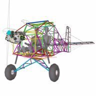
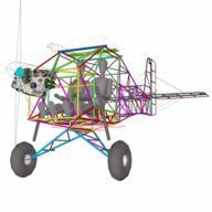
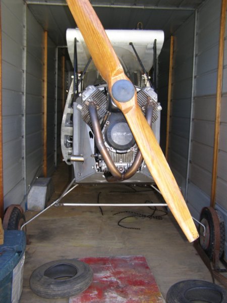
SD, I can't quite agree with your 'order of magnitude' for the three projects. I'd say the Iolaire is likely to be the most benign of the three, probably closely followed by the Quaiche. That said, I'd want to check the Quaiche CG carefully because unless it has a disproportionately heavy engine it looks a bit stubby in the nose so the CG might be a bit aft - that all depends on the weight of the aft fuselage structure of course. I'd think that the real challenge will be the Sgian Dubh. With the weight in it's ends (pilot up front and engine down the back) it's likely to be very nasty if it ever entered a spin (would possibly want to go flat) and will probably have very limited pitch and directional stabilities since it appears to lack any effective sweep in the mainplane. It's not very clear in the photos, but from the little you can see it doesn't appear to have much, if any, reflex in the airfoil section either, if that's the case it could even be pitch unstable. I hope I'm shown to be wrong, but the only plane I'm aware of that got away with similar design features was the Pelican, and you can see how much effort has gone into getting the major weights as close to the CG as possible, and it has a lot of reflex - Though I've not seen a true planform view of it, the Iolaire would appear to be a very conventional canard design albeit rather difficult to access the rear seat. I question the opinions of your 'aerodynamicist'. If you have doubts about the design I wonder whether you might do better to get the opinion of an aeronautical engineer. Aerodynamicists rarely know much about 'whole aircraft'. I'm not talking out of my ass, I know two of them very well, one is my nephew. Both were trained in Universities in England and whilst they are exceptionally knowledgeable about fluid flow around and over specific shapes, neither of them has any knowledge whatsoever about aircraft. My nephew read for his Degree because he was fanatical about the McLaren F1 team and wanted to work for them, he can tell you the most precise details about the fluid dynamics of the flow into or out of the radiator ducts for instance, but wouldn't know much about a canard's overall design requirements. Referring to your aerodynamicist's comment above - well of course the canard could adopt a lower incidence than the mainplane - it's a control surface, and when you want to put the aircraft into a dive the canard will have a much lower incidence than the mainplane, but so what? In a dive the mainplane's not going to stall is it? Going back to basics you will recall that the best indicator of the potential to be approaching a stall is the stick position, when the stick is back you may stall, right? So when the stick is back the canard is at a high incidence compared with the mainplane isn't it? So the canard will stall first provided the CG is in the right position for a canard-style aircraft. As long as the CG is well forward of the mainplane, and consequently the canard is much more heavily loaded than the mainplane then the canard MUST stall before the mainplane, if the plane is capable of flight at all, and I don't see any reason why it wouldn't be capable. The underlined items previous are the critical factors for safe canard operation. Many people don't understand canard dynamics properly and consequently make quite erroneous comment about them, on occasions. Of all the aircraft I've flown, the one I found to be the easiest, most forgiving and what I would describe as 'completely docile' is of very similar fundamental design to the Iolaire, the American Aircraft Falcon, even Chuck Yeager liked it -
-
Hi BD5-C, welcome to the forum. Great to hear about the BD5 imports, cute little aircraft though they might be considered a little unforgiving in their handling characteristics for a new pilot. Their flights per fatality statistics were rather drastic at one stage, IIRC the major issues were stalling in the circuit due to uncommanded pitch-up from blanketing of the elevator as the pilot slowed down in the circuit. I'd guess you'd be well aware of their foibles? The Cozy is supposed to be a kindly handling aircraft - you don't think it might be a better one to build some experience in before flying the less forgiving BD5? What mods are you planning for the Cozy? And why change it from standard?
-
Fundamental AIrmanship Principles
Head in the clouds replied to dutchroll's topic in Aircraft Incidents and Accidents
I quite agree Marty, it's hard to believe it can happen, but it can, and does, even to the best of us. Sander Veenstra is a name well known to anyone who was around the ultralight scene in the late 1970s and 80s. Sander was probably the most prolific builder of planes in Australia. He had a workshop that I spent a lot of time in, at Officer, near Berwick to the East of Melbourne. By around 1983/4 he had outgrown that workshop and he moved to Tocumwal for a short while then purchased a tract of land that had a private airstrip and large shed at Nagambie, near Mangalore. The demand for his planes was strong and for some time he had been building planes in batches of six and was working all hours, both to meet the demand, and to pay the substantial debt he'd entered into. Initially he'd been building planes that were most like motorgliders, they had a single wheel, inverted V tail and a relatively small 18hp direct drive pusher engine. He was achieving glide ratios around 18-20:1 and he'd attracted the attention of some notable people, Bert Flood, for example, owned a number of Sander's planes and Sir Jack Brabham was another keen participant. The ultralight market, however, was moving toward more conventional powered planes and the design of each of Sander's new batches were morphing that way a little at a time. By the time of his sad event his planes had a conventional two-wheeled taildragger landing gear and the V tail was now upright rather than inverted, they were a very slick little machine called the Farmate (or Farm-mate) - that was the eleventh production design and he'd built a total of around 50-60 planes by that stage including two two-seat trainers, a single engined tractor design and twin pusher called the Tardis that's still around, I last saw it not too long ago at Watts Bridge in Queensland. I don't know all the details because I'd moved away from the area shortly before the fateful time, so the rest was told to me by others. He had almost completed the latest batch of six when he ended up making a change to the control system. I'm not certain whether he had decided to change the whole batch, or whether he was upgrading a plane that came in for servicing to the current spec, either way the design change moved the engine mounting a little, repositioned the control mixer for the V tail and, if I understand it correctly, also moved an overhead bellcrank for the aileron pushrods near the mainspar mounting. Sander was tired but always gave a comprehensive test-flying regime to each plane before delivery to, or collection by, the customer. The changes had delayed the completion dates and he was in a hurry to meet agreed delivery times. He fired it up, completed his taxi and controls checks, applied full power and took off, climbed straight ahead to 150ft or so and, confident pilot and person that he was, he rolled hard into a left bank. Or rather he tried to, the plane flicked into a spin and impacted the ground more-or-less vertical, it was all over in a second. The accident investigation was straightforward, Sander's modification had reversed the sense of the aileron operation and he, talented and meticulous as he was, hadn't picked up on it during the conversion(s) nor during his pre-flight controls check. Even though he was a long-time glider pilot - and glider pilots are very careful with the 'free AND correct sense' checks, because gliders are assembled and dis-assembled so frequently. Those who knew him well put it down to hurrying due to tiredness and financial pressures, but it's still astounding to think someone so experienced and knowledgeable could have missed that issue for so long, he would have been 'around' the matter for days while doing the work on them. We lost a very talented designer/builder that day.
-
DooMaw - building a STOL
Head in the clouds replied to Head in the clouds's topic in Aircraft Building and Design Discussion
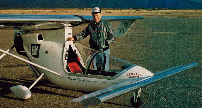
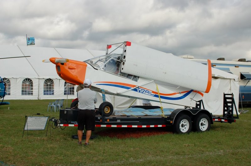
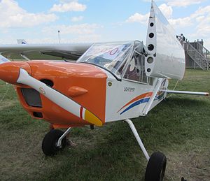
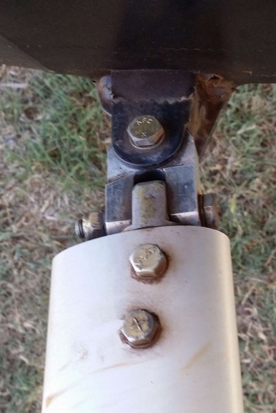
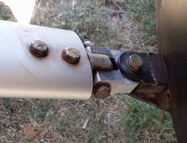
For those who may not know the Trail, it has a wing-folding system that also folds the wings flat against the fuselage but it's the front spar connection that remains connected when folded, rather than the rear spar connection. This has the very distinct advantage of making the whole folded package shorter but it has two disadvantages - The folded package is very much taller. That doesn't matter if you're only going to store it in a hangar (as long as you've got very high hangar doors) but for trailering it means the windage on the side is substantial and requires more care when driving. That's not to be scoffed at, I lost a very good friend in the late 1980s when their ultralight plane's trailer was blown off the road by a willy-willy taking the tow-car with it and they hit a tree. When folded the majority of the wings' weight is above the spar attach point and so the wing is unstable and requires additional bracing members to hold it in place when trailering, that takes additional time to install when folding and unfolding the wings. Here are a couple of pics of the Trail - Some while ago I was quite astounded to find that in general engineering bolts are used in tension whenever possible and in shear only if a tension orientation cannot be achieved. It's only in aircraft that you see a lot of situations where the bolts are used in shear, and this is mainly where the same bolt can be used in double, triple/multiple shear, like a wingspar folding knuckle, or where rod-ends attach on a control pushrod, for examples. Interestingly a 'proper' bolt can realise its full tensile strength against the thread of the nut and in testing should elongate and eventually snap at the transition between the thread and plain shank. The (single) shear strength of a bolt is only about 2/3 of the tensile strength. For a very relevant example of 'general' engineering using bolts in tension - ALL lifting lugs (craning points) are attached using bolts in tension, never in shear. There is a caveat to the above though - the bolts must always be properly torqued to the correct values for the bolt size and threadform to prevent the thread fretting when loaded and unloaded, so the 'loose' bolt for the rotation in the upper strut assembly of the Groppo is an absolute no-no, eventually the threads must wear out from the cycles of flight loading. OK, the 'diaphragm' aspect. I agree, it's not attractive from an engineering viewpoint on the Groppo but I suppose all bolts in tension are acting through a 'diaphragm' arrangement in some sense, it's just the thickness of the diaphragm that varies, make it thick enough and you're bolting through a block ... which is the direction I'm headed, the bolt used for the rotation goes through a thick aly block which is milled to provide a pair of cheek plates/clevis for the connection to the next part. Going back to the bolt used for rotation - I can't see a way around using it in tension, and for the reasons given above, there's nothing wrong with it at all but I will be trying to source a long nut, or machining my own from chromoly. There's probably no need for that but if it makes me feel better ... Then, that bolt must be fully torqued and that means it must have a sleeve on it and be torqued up onto that, and the rotation takes place around the sleeve rather than just around the bolt. ...................... Referring back to your photos of the Groppo strut-to-wing attachment, it has one axis of freedom (hinge) and one axis of rotation. When I studied The Mistress in the same location it has two axes of freedom plus the rotation. I haven't actually made a model of the system but I have been wondering if the second axis is really necessary and the Groppo photo shows that it isn't essential BUT you can see that if you don't rotate the wing as you extend it, exactly at the time and rate that the geometry demands, then you will be stressing the attachment fittings. The second axis prevents this stressing, as far as I can see at this stage, and means that all that is necessary is that you rotate the wing at some time between the folded and extended positions. Incidentally, the upward angle on the lower strut attachment fittings that you commented about previously, apart from aligning everything when the wings are extended for flight, does serve another very useful purpose. When the wings are folded the strut 'slumps' into the folded position which means that even if not secured back the wings will not inadvertently swing forward if the tail is lifted above the horizontal, this could save a lot of red-face in the hangar ... I'll post some photos below, of the fittings on the Mistress upper strut end, and also of the rear spar attachment. The latter is a rather untidy affair and is probably the result of a bit of trial and error on the part of the designer/builder (he was a German toolmaker and obviously very talented). It's an arrangement whereby a small member carrying a hinge in one axis swings out on the other axis (when it isn't swung out both axes are locked with a vertical pin), I have in mind to make that a lot tidier with a similar connection to the lower strut fitting, getting rid of the need to remove an extra pin, with the associated hazards of forgetting to replace it before flight. The Mistress's version does however provide the benefit of elongation in that area when unlocked which gives extra clearance for folding as the flap control rod disconnects and the flap droops - I'll use a spring to hold the flap up instead, and a small removable fillet fairing. The first photo shows the upper strut fitting on the Port side. The bit that is bolted into the end of the strut carries the bolt for rotation, then there's a heavy clevis with vertical bolt for fore/aft motion (in theory I think that's the one that isn't entirely essential but might be better considered as 'good practice'), the clevis carries a block (like the lower strut fitting) with horizontal bolt for vertical strut motion which allows the strut to nest against the wing underside when folded. The rest of the pics show the Port rear spar fitting unpinned but with wing extended, Starboard rear spar fitting, first with wing extended and pinned, then with pin removed, then with wing folded and last pic shows the lower strut fitting with wing folded.
-
DooMaw - building a STOL
Head in the clouds replied to Head in the clouds's topic in Aircraft Building and Design Discussion
Yup, the wing folding on DooMaw is rather more complex than the single-plane type of folding that the Kitfox and similar have, because when they're folded DooMaw's wings lie flat against the side of the fuselage (a bit like the Grumman Avenger, but even more so), consequently there's two axes of freedom and rotation at the top strut fitting and two axes of freedom at the rear spar attachment. Because of those multi-hinged points, and because they're not arranged as a star-fitting (like a universal joint) but are offset hinge-lines, the lower strut hingeing wouldn't be aligned with the others even if it was pinned vertically. I was quite intrigued when I came across M61A1's "The Mistress", which is where I first saw this very clever and useful hingeing arrangement. I've tidied it up a bit for DooMaw but unfortunately I still wouldn't be justified in claiming the design as my own, even though it will now be the truly 'instant' wing-folding method I've always hankered after. The other two attach points are a little difficult to describe at this stage so I might have to leave that until I have modelled it in CAD and can show the actual components in an exploded view, but for the meantime here is a picture of The Mistress's lower strut attachments to be getting on with, they should show how DooMaw's swivel alignment will be achieved, it has the same effect as yours on the Stollite - the third pic shows The Mistress in her trailer note that the wings are on the plane, you can just see them folded flat down the sides of the fuselage, and they're still attached to, and supported by the struts. This type of hingeing provides two massive benefits when compared with the type used on the Kitfox and similar - you can still walk around in the trailer because the wings don't take up its full width, and your wing-chord width isn't limited by the need to get it into legal roadable dimensions.
-
DooMaw - building a STOL
Head in the clouds replied to Head in the clouds's topic in Aircraft Building and Design Discussion
April 12th, 16th-17th. I've always had a bit of a 'thing' about strut attachment points. On any plane I've built I've seemed to consider them the most vulnerable to failure of the entire structure. It's probably a completely unreasonable concern but if it's there, niggling away at you it's a bit harder to relax and enjoy the flying. I'd pretty much stopped worrying myself over it and then a well-known brand of Aussie plane had their wings fold, and another nearly do so, due to corrosion in the carry-through, so I began to consider my fears justified again. Consequently, during the design phase of the DooMaw I had a close look at numerous steel-framed aircraft to see what solutions previous designers had adopted for their lower struct attachments. I saw quite a variety, some that looked like they could lift a tank and others that frankly gave me the willies. Anyway, seeing how incredibly light some of them are, and still manage to keep the wings in place, was an education in itself. It's not that their design is anything particularly arduous, it's easy enough to work out how much material is required to satisfy the tensile and compressive loadings at 6G plus a safety margin, it's more the problems that can arise due to corrosion, shock loading from landing and ground handling, and in my case, the completely different loading direction that's imposed when the wings are folded and the plane being trailered over rough roads perhaps, because the wings are still being supported by the struts when it's in the trailer. So - this time I wanted strut fittings that can take whatever's thrown at them, and to be honest that's why they're being added at this late stage of the program, because I've taken this long to decide exactly the best way to make them. Once the design was completed I just had to do the usual spray-paint templating, cut them out, make spacers on the lathe to clamp between them, drill and ream them, fit them up, grind the weld prep angles, tack and weld them. Sounds simple but took three long days. The lower plates are simply tuning-fork shaped and bent at 29 degrees so that each arm of the fork welds down each side of the very substantial 1.25"/32mm x 0.125"/3.2mm carry-through tube, then the top plate is made up from three parts where the fork arm is above it on one side and below it on the other side, this is to fit around the bend in the lower longeron. The pictures should tell the rest of the story, the assembly is mighty strong, I don't think I'll need to have any concerns about it ... Another 26hrs for the log, a total of 1034hrs so far.
-
Hi Hasse, don't worry, your English is better than many Aussies ... so you can be Ingmar Hasse from now on! It's good to see your tests but you need more 'controls' to really draw any conclusions. Total vapour pressure won't tell you much, since both of those fuels are compounds and one is a mixture of several compounds. If you were to accept my version of the 'rate of vaporisation' being the issue here, then it would be the rate of the vaporisation of the fastest of the components of the mixture, that is relevant. So, if your mixture 'A' contained ethanol, for example, that ethanol would probably be the fastest to vaporise even though the rest of the fluid is still liquid and has not yet evaporated, and hence the test piece subjected to the fluid containing that alcohol would be cooled much more rapidly than the other piece. However, if you are convinced that the polycarbonate is actually being chemically attacked by one or several of the components in the fluids, then the control test is very simple, immerse some flat Lexan in that fluid for as long as you like, and take it in and out several times, allowing the fluids to evaporate each time, and see what damage that fluid does to the Lexan. If there is no damage, as I contend will be the case, then the fluid does not attack the polycarbonate chemically, and the damage we see on windshields has only to do with the internal stresses in the sheet material when it is curved. If the polycarbonate material is not chemically attacked by the fluid then it is being attacked by something else - and I think you will find it is to do with very rapid heat loss on the outer surface. Further tests you can conduct - warm your test piece gently in an oven or with a hair-dryer before curving it and subjecting it to mixture no.2 (aircraft fuel). Try another test with an ambient temperature test piece and aircraft fuel but this time have a fan blowing on the experiment to increase the rate of vaporisation (and hence rate of cooling). Try dipping your hand in each of those fuels, when you take them out does one feel colder than the other as it evaporates? Swap hands and do it again to be sure ...
-
Horn has cross strips as you know, I don't think you'll have any problem regardless of how hard it's blowing, the air is smooth because it's coming off the seas whichever direction it's blowing. You mentioned about seeing New Guinea - the nearest Highlands are about 250Nm north of Horn. I went out as far as Badu Island but couldn't see anything of NG, mind you it was perma-haze while I was there. I've attached a few photos, the first two show the Cape itself, the next two heading towards Horn, then Horn airstrips, some of the cloud patches along the way, and Princess Charlotte Bay. Crossing the really high cloud street I mentioned earlier was a little bit nerve wracking so I didn't think about photography at the time but as you can see I was still up around 9000ft to clear the later ones which were a lot narrower and much lower. That trip was in September 2005, so the weather conditions could well be quite different at this time of the year. Also I was late leaving the Cape, that photo was taken just north of Princess Charlotte Bay and it was already 12:41pm. If you get a chance to catch up with the QANTAS-link or Coastwatch crews at Horn for a chat, they're a wealth of information about conditions up there, which are quite different from further south. I was surprised to hear what you said about only one strip at Burketown but I see from G Earth they've closed the 12/30 strip that I used to use. Later I was able to land under the powerlines on the roadside opposite the Burketown pub, but that was easier in a Jetranger than the plane of course ... and a lot shorter walk.
-
Pretty normal in the low latitudes. Generally much less wind in the very early morning and overnight. Up there - top of Cape York in particular - when the SW blows it gets calmer as the seabreeze kicks in and opposes it. Other times if it's not a windy day it's dead calm, hot, humid and hazy, not much in between.
-
That's very sad, I wasn't even aware he was ill. His passing is a great loss to Australian aviation and to all who knew him. Wicked sense of humour too. Sincere condolences to family and friends. RIP Howie.
-
I'll look forward to seeing the video of your test. I'm inclined to agree with rankamateur's comment above. It's all about the rate of evaporative cooling, and has nothing to do with the chemistry of the liquid being splashed on the plastic. If the fuel with aromatics evaporates faster in the ambient conditions being experienced at the time, then the damage to the screen will be worse, not because of the aromatics attacking the plastic, but because of the faster evaporation rate. Note - it's not how cold it gets eventually, but how quickly it gets cold. In a couple of months I'll be fitting the windshield to the plane I'm building so I'll have some polycarbonate offcuts I can use in some new experiments to demonstrate this. It's very relevant to me too, because my fuel filler is in the lower right hand corner of the windshield - the main tank is behind the instrument panel and it's a taildragger, so that's the only practical place to have the filler cap, like a Wittman Tailwind see picture below. Having the filler there means that fuel will often get splashed on the windshield and it doesn't worry the Tailwind, not will it worry mine, because the windshields are flat, so they're not under stress when installed. Actually the Tailwind's windshield is very slightly curved, but evidently not enough to cause stress-cracking problems.
-
Live prop nearly kills a pilot
Head in the clouds replied to rick morawski's topic in AUS/NZ General Discussion
You probably don't want to be too quick to judge. Although I always do mag checks after landing you'd never know it unless you were in the plane with me because I do them while taxiing back to save time. Consequently as soon as I reach the apron I can pull the mixture and shut down. -
Aircraft down Lancefield Vic
Head in the clouds replied to red750's topic in Aircraft Incidents and Accidents
I made a comment about belligerence previously, then there's also the word 'obstinate'. Being either of them certainly makes it a lot harder for anyone to have their ramp check conducted amicably. That's their choice, personally I've never experienced anything but politeness and civility from DoA, DCA, CAA and CASA variously, and that's during dozens of ramps over a twenty year commercial career. Others' mileage does vary ... You may be being a little 'particular' about the word 'log'. At the bottom of the manually-filled flight-plan form is an area which allows you to fill in the amount of fuel loaded, the taxi time, flight time, amount remaining for each leg of a flight, then the next set of boxes at the bottom of the same form has spaces for you to fill in for the amount of fuel loaded for the next leg, taxi time, fuel burnt etc etc and each has spaces for the required reserves which vary according to the type of flight you are conducting. This is known as the fuel 'log'. It's not expected that you make any entries en-route on a single leg of a flight, or on a flight that only consists of one single leg. Nonetheless you're still required to have at least the correct amount of fuel to conduct the flight safely and that takes weather into account. If you're required to have the correct amount of fuel AND you're required to prove or demonstrate that fact to a CASA Inspector (the Investigator comes later after you've been shown to have stuffed up), how will you demonstrate that you've complied unless you can produce something you've written down about it previously? CASA aren't breathing down your neck and telling you how you must keep this 'log', they're allowing you to be responsible and do it however simply you wish, as long as you do it somehow, and can show that you do it. I don't think that's at all unreasonable, and I think it's the least we can expect otherwise what answer will we have for our critics (the general public on the ground who see us on the news too often) who wish to have our sport banned each time some twit runs out of fuel ...? There are two kinds of people of who run out of fuel of course, those who knew they were and those who had no idea - if you have a log at least you hopefully knew you were too low on fuel. Similarly your Nav log can be as informal as you like, as long as you can demonstrate that you knew where you were, and when. By all means fly with one EFB and nothing else, since you're entitled to do that, and have fun finding yourself when it fails ... I still enjoy Nav so my primary nav is just as it was back when I was first taught. I draw a line on a chart and mark it off in 10Nm segments in pencil. I make a note of the time of departure and enroute I note the time that I pass distinctive features, or reach a 10NM marker, or enter/leave airspace. I cross-reference that with my GPS to reduce my workload but if the GPS fails it's no more than a minor inconvenience. When the rampie asks for my Nav log I show him the chart and notes, what could be simpler? There's no requirement to carry a 'last page of logbook' (meaning evidence of BFR currency) but I do carry a photocopy of mine with my licence because it saves me from having to produce that evidence later, but that's up to you, no-one says you 'should' carry it but it doesn't hurt to have a copy in your flight bag and save yourself some hassle. If your BFR and membership renewal coincide then your BFR date shows on your pilot certificate (for RAA pilots). You really do come across in a way that indicates you resent being ramped at all KR, and that's pointless because the CASA are required to police the air regulations just as the traffic police do on the roads, and that's not something that's going to stop just because some people don't like it. During a ramp check I've never been asked for anything I'm not required to carry, nor anything I haven't needed to have, to conduct the flight safely. You've made these statements but not provided any references so I can't really comment. Perhaps they're referring to a photo ASIC? Where is this "naturally be aware" comment made? You say that's what they say, but you don't say where they say it ... Which are the incorrect references and statements in the GA ramp check guide (which I've also pasted below)? I’m a GA pilot and have been selected by a CASA inspector for a ramp check What happens now? The inspector will ask you for your CASA pilot licensing documents Flight crew licence (FCL) – You must carry your current licence and photographic ID. [Paper or electronic copy of licence acceptable] Aviation medical certificate – You must carry your current aviation medical certificate. You must be compliant with any restrictions or endorsements (e.g. the wearing of corrective lenses)[Paper or electronic copy of medical certificate acceptable] The inspector will then check your preparation for your flight Flight plan Have you maintained a navigation/fuel log? Have you made a careful study of forecast weather and applicable NOTAMs? Are you compliant with CASA flight time limitations (as applicable)? Are you carrying the appropriate, current charts and documents? Are they easily accessible by the crew? Are you using an EFB for your charts and documents? There are considerations for commercial versus private operations. Have you submitted a flight plan (if required by AIP)? Finally, the inspector will check your aircraft The inspector will check: Aircraft maintenance release Is the daily inspection signed off correctly? Are all required airworthiness directives completed and signed off? Are there any outstanding aircraft unserviceable items to be signed off? Flight manual (if required)– is it up-to-date? Checklists (normal and non-normal) — are they up-to-date and accessible to crew. [Paper or electronic copy of checklist acceptable] Evidence of pilot and passenger weights (standard weights should not be used in aircraft with fewer than 7 seats) Evidence of cargo weights (if carried) and appropriate securing equipment. Load sheets (if required) Required emergency equipment on board, serviceable and accessible. Document references Flight crew licence & aviation medical certificates Carriage of documents – CAR 139 Flight review – CAR 5.108 Recent experience – CAR 5.109 Operations Navigation logs – CAR 78 Fuel requirements – CAR 234 Weather and NOTAM – CAR 233 & AIP ENR 1-10 paragraph 1. Flight plan submission AIP ENR 1-10 paragraph 2. Flight time limitations – CAO 48.1 and CAAP 48.1 Charts and documents – CAR 139 and AIP ENR 1.10 paragraph 5. EFBs – CAO 82.0, CAR 233 and CAAP 233-1(1) Aircraft Carriage of maintenance release – CAR 139 Carriage of flight manual – CAR 139 Check lists – CAR 232 Carriage of passengers – CAO 20.16.3 – CAAP 235 Carriage of cargo – CAO 20.16.2. Load sheets and passengers lists – CAO 20.16.1 Emergency equipment – CAR 252A – CAO 20.11 *Regulation details current as of December 2013


.JPG.98a3ee9755014217be241299a041c439.JPG)
.JPG.fbd28c7e1147217e1ccbeb0e4cc63918.JPG)
.JPG.505a5f8141ac3725e4b28b2c6f90e93f.JPG)
.JPG.8cbe81411642e018ad616f13dad9eb36.JPG)
.JPG.9e6025b7ce02795e22a4bd031a477d6d.JPG)
.JPG.4d3828505f0601d5cd612c299f304e70.JPG)
.JPG.8b4774fd7718e97aeda421371bf6f674.JPG)
.JPG.7ee89692ebe069837ec8ae7608cbd824.JPG)
.JPG.a622d2336fd7252514e49e37bfb5c9a0.JPG)
.jpg.b5882d7edc06a316a5b6e74838eb912a.jpg)
.jpg.01abe2400d45e9b233c89584f6a179ad.jpg)
.jpg.1cf79e3a1e4b5704dbdbb6ff7ab6b896.jpg)
.jpg.09e066d7cfde7f5a073b2613670cc494.jpg)
.jpg.21962834dfacb92be0c0101fdade47c1.jpg)
.jpg.b645c1edad8f260c7d607c1f4b38b9e0.jpg)
.jpg.81356001f8e709c60f5a2dc7d8531f6c.jpg)
.jpg.0905e007dbf440438bab21a742941a58.jpg)
.jpg.7bbb4938e13386a0986ab2250a9dc59e.jpg)
.jpg.610d03843f6f196e195c569a084ed001.jpg)
.JPG.cba65511f601799bf553983d59275a20.JPG)
.JPG.32ca569d1e592bca522194b9d4c97c12.JPG)
.JPG.de55a02313f3eebe1a89cb146018ed8d.JPG)
.JPG.d6d4101bd55c0f7098907ecec905b707.JPG)
.JPG.7b2189cbe7092120d41aaeeddeb7c681.JPG)
.JPG.0b38dd58bb986605e89815ef56a8a2cd.JPG)
.JPG.07a8fa53a0303c6285fb944b8df72b63.JPG)
.JPG.a9ca3818c8687d2951a2a86482b11845.JPG)
.JPG.03149214c5844037a42fafebe25ea131.JPG)
.JPG.fcfde053e0f38ebd5ac1be8e51e8cfea.JPG)
.JPG.84e35cb6d90eed8fc2f25afbf064511a.JPG)
.JPG.3400fc9ba59048956a2ddb852478800e.JPG)
.JPG.9ddcde93d738f07e72dd1d53162d9aa3.JPG)
.JPG.277d4d6da74b16953ac2e179a3ec3182.JPG)
.JPG.bc93853b0b3f82c13a1a28800c2b0589.JPG)
.JPG.b96aee524829924dd6ce634bbae86b53.JPG)
(Custom).jpg.e72681d4f62a9f445f7fb82dbb943434.jpg)