
Head in the clouds
-
Posts
1,842 -
Joined
-
Last visited
-
Days Won
42
Content Type
Profiles
Forums
Gallery
Downloads
Blogs
Events
Store
Aircraft
Resources
Tutorials
Articles
Classifieds
Movies
Books
Community Map
Quizzes
Videos Directory
Everything posted by Head in the clouds
-
DooMaw - building a STOL
Head in the clouds replied to Head in the clouds's topic in Aircraft Building and Design Discussion
It's nice of you both to say things like this but those of us designing and scratch-building these days had to start somewhere too, we weren't born with the knowledge of how to go about it all. I truly admire those of you, like Biggles and a quite a number of others on this site, who take on a kit build and finish it, because at the outset many of you often don't know what you're letting yourselves in for. And there are so many first-time builders who make an absolutely fabulous job of the build. My main motivation in writing about this DooMaw build on this site is in the hope of encouraging more people to consider designing and their own build, or assembling a kit, there's so much satisfaction in flying something you've lovingly nurtured into life. As for feeling inferior, well I hope that's just a humble and kind comment because there's certainly no need to feel that way. We all had to start somewhere and when I started I made some terrible mistakes which would have killed me had others with more knowledge than I, not taken me by the hand and helped me along the way. I'm still learning lots too, there are so many fabulous people on the net these days who will talk all day about aeronautical design and construction. I first built a very lightweight trike back in the 1970s, it was not too bad because I mostly copied it from one I flew in, in France while on holiday. In 1981 I started on the 3 axis machines and as I said, it would have been disastrous if others hadn't stepped in and given me some quite stern and very sound advice. I am eternally grateful to people like Sander Veenstra, Robbie Labahn, Werner Bekker, Gordon Bedson, Ross Nolan and quite a few others, most now sadly passed on. If anyone has thoughts of getting some of their ideas on paper with a view to perhaps turning them into a real project, they're more than welcome to contact me and I would be glad to help if I can. -
My highly treasured Nikon Coolpix P600 which is an astounding little unit I bought for a trip to Kruger Park earlier this year. It looks like an SLR but is tiny by comparison and about a third the weight, small enough to take it everywhere. It doesn't have interchangeable lenses but I haven't needed them because the zoom goes from very wide angle (equivalent of 24mm on my SLR), to 60x (that's optical zoom, not electronic) which is the equivalent of a 1500mm lens on the SLR. One of the many really amazing thing is the image stabilisation which allows you to take crystal clear hand-held shots at the full 60x zoom. I couldn't get that out of the SLR with a lens of anything more than 300mm ... and that's in bright lighting. Better still, I picked it up in a JB HiFi sale for just $300. I think I recall you're keen on photography Doug, so I've attached a selection of the 3000 or so pics I took on that trip, size-reduced for the site but you might like some of them anyway -

-
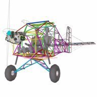
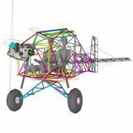
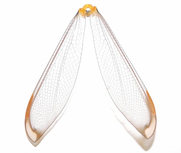
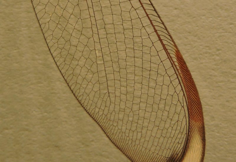
I guess the ants got hold of an insect with beautiful wings, because I found these on the verandah yesterday - On close inspection the structure of them is truly astounding. Nature is almost invariably right about the best and most efficient way to go about things, and finding these reminded me that some fella in the US was working on replicating the structure of dragon-fly wings for use on an LSA-type aircraft. IIRC he had made one set of prototype wings, I think they were about 3-4m span, so about half scale. He made them without molds, by winding strands of glass and carbon fibre around nails in a curved board and then infusing them with epoxy resin. I recall that they were working well on a large model with quite a heavy wing-loading. Although the structure was similar to the insect wings he'd changed the shape to suit powered/gliding flight rather than ornithoptering. The covering, or clear part, was Tedlar or Mylar and the interesting aspect was that the wings were un-strutted and designed to be flexible like a fishing rod. This meant that they didn't need to have a 6+G capability because under load they would flex and 'spill' air, thereby unloading themselves, in a similar way a mono-hull yacht unloads the mast by heeling under a sudden gust. I haven't seen anything about it since then, and can't find anything on the net at the moment other than for use as flapping robotic drones - I last saw it about 4-5yrs ago - so I was wondering whether anyone else has kept up with his progress, if any?
-
DooMaw - building a STOL
Head in the clouds replied to Head in the clouds's topic in Aircraft Building and Design Discussion
Yup, I'm afraid there are certainly traces of nuts OCD in this household ... My day job also involves a lot of quite complex problem solving and I would estimate that more than half of the answers come to me while sleeping. At one stage I used to keep a notepad by the bedside, but later found that I always recalled the thought in the morning, if not immediately upon waking then at least within an hour or two, so that saved a lot of scribbling notes in the wee small hours. And yes, I know what you mean about discovering the answer to a previously unperceived problem too - a marvellous thing is the brain, working away studiously while the rest of the organism is asleep. -
DooMaw - building a STOL
Head in the clouds replied to Head in the clouds's topic in Aircraft Building and Design Discussion
Thanks for the kind words again Oscar. As you know, building a plane is a long road - and building rather than being out flying is sometimes rather tedious, so the encouragement is much appreciated. -
DooMaw - building a STOL
Head in the clouds replied to Head in the clouds's topic in Aircraft Building and Design Discussion
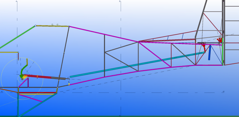
The welding magnets you describe are predominantly used for holding parts together for SMAW/MMAW (stick electrode) welding, where the magnetic field has a lesser effect on the arc. Even then you remove the magnets as soon as the parts are tacked or you will end up with a very messy weld. You can just about tack parts held with a magnet if you are GMAW (MIG) welding but it can be messy, and it's virtually impossible to tack or weld with GTAW (TIG) if you have a magnetic field emanating from the parts, the arc goes anywhere except where you want it to go. 29th Nov - 22nd Dec, 2015 contd ... As the fuselage structural assembly nears completion I had to firm up the design of the control runs. I was a bit slack in that regard about a year ago, and a bit keen to get on with some practical work rather than spend more time at the computer, I'd already been working on the CAD side of this in spare time for close to two years, so having confirmed that I had the clearances to get the controls in place, the motions of the elevator and rudder were unhindered, and the wing-folding geometry didn't cause any clashes, I was pleased to get onto some time in the workshop. I had already confirmed the shape and position of my elevator control horn which is tucked between the fin/tailpost and the HS rear mounting bracket and that it can just accommodate the required 50 degrees (25 degrees each way) of motion. I found I needed one bellcrank, one walking beam and three pushrods to connect it to the joystick. The screenshot below shows the development of the geometry - I tried every bearing and engineering supplies shop within 100km or so to try and get suitable bronze bushings for the bellcrank and not only couldn't I get suitable ones, I couldn't get any at all. The best they could come up with was a 12" length of 1" diameter phosphor bronze and since I already had a couple of them I set to work and machined the bushings instead. It just shows the dreadful state of industry here these days, considering that bearings of all kinds are the backbone of engineering. The walking beam has a similar amount of angular motion - around 50 degrees total - but the bushings are under very small load since both connections are on one side of the bearing rather than on opposite sides, so the bushings for the walking beam are mild steel drilled eccentric to provide clearance between the moving and stationary parts. The moving part will have an oiling hole for lubrication at each hundred hourly or annual inspection. The pic below shows some of the bellcrank and walking beam hardware awaiting assembly - Although I'm not concerned about the boxy shape of the fuselage front and rear I do want to provide reasonable airflow over the empennage so I have two fairing battens external to the structural steel, one on top which fairs the dorsal fin into the rear fuselage, and one below which eases the 'step' which would otherwise exist right behind the rear landing gear mount. Those battens are 20x10mm Tassie oak because it is less than half the weight of even a small 3/8"x0.035" CRMO tube. The battens are attached by 0.040" steel plates bent into an angle, and are infuriatingly tricky to get aligned properly because regardless of setting them up straight the welding pulls them all over the place. I got them right in the end. The forward bracket for the top batten doubles as an attach point for the forward end of the ventral fin. I also added some bent steel tubes forward of the HS mounting to shape the fabric to meet a 'removable for inspections' GRP fairing at the HS/fin intersection that will cover the elevator pushrod and bellcrank. I then added handles to the sides of the rear fuselage for ground-handling because otherwise the only thing you have to get hold of is the leading edge of the HS and that doesn't do the fabric any good over time - Added the plates to the corners of the firewall which attach the engine mount - Completed cutting out the floors and gave them a first coat of clear poly - Roughed out and trial fitted the instrument panel, it attaches to the mounting plates via rubber anti-vibration mounts so the whole thing can move around slightly, and also makes it easy to remove for any work required behind it. It'll have chromed dome-nuts on the front side eventually. Finally I started making the joystick hardware ready for assembly - Reasonable progress for the month, another 39hrs in that lot, making 528 hrs on the project so far.
-
MiniMax uncovered
Head in the clouds replied to Soleair's topic in Aircraft Building and Design Discussion
Sorry Scott, you may be passionate about it, but with respect, you're misguided. Those handheld radios aren't that cheap, and they broadcast and receive just as well, if not better, than the TBO'd panel mount units. This is not conjecture, it's something I've checked and verified on a number of occasions as part of my near two decades commercial operations in remote areas. In mining sampling operations, for example, peoples' lives depended on those Icom handhelds, and they work fine as a base or airborne station provided the installation and antenna is right. In fact there have been many times when my fixed installation Icom handheld outperformed the $4K B-K panel unit. As far as the power supply is concerned, if you're familiar with the Icom handheld you'll be aware that the battery pack isn't there in Soleair's installation. When you remove the battery pack those units have a 'hot shoe' that provides connectivity to the aircraft's power system, or alternatively you can plug in the power supply to the charging socket on the side near the base. Now - what about aircraft that don't have a power supply? Many Tiger Moths, VW powered ultralights, in fact just about any sport aircraft that you see being hand-propped doesn't have a battery or charging system - and nor are they required to have. Are you suggesting that they shouldn't be able to use a handheld? Bear in mind that many have been doing so for decades with perfectly acceptable results. They're not 'optimised for rubber-resistor antennas', they simply have a 3W (or whatever) output and you optimise your antenna for the best possible signal strength and directions. From what Soleair has said it sounds like he knows what he's doing. I'll look forward to hearing what his radio sounds like compared to some others ... In any case the poor transmissions you have experienced from time to time are very unlikely to have come from someone using a handheld, it's far more likely that it's someone with an ageing installation of a quality panel mount but with a poor antenna earth, or a broken/corroded antenna core. Or just as likely a microphone that is overdue for replacement, some people seem to think microphones last forever ... As for the legality of using a handheld airborne, you might do a little reading - provided the installation is appropriate there is no restriction against it, since they are a unit that is approved for use in the aviation frequency band, there is no differentiation about where it is used. And since we don't yet, thankfully, require annual release notes on our avionics, the installation is, gladly, left to us as homebuilders. Just watch that change when folks get their wish about CTA ... The other option, for many people, would be to not install a radio at all. I'm sure you're aware that they are not compulsory? Would you prefer that more people didn't carry a radio at all? The primary separation method below A050 and OCTA for all aircraft is still to 'see and be seen', which of course means that the primary means of collision avoidance is looking out the window rather than relying on anyone doing anything with a radio ... consequently, as far as your plane, or yourself are concerned, it's quite impossible to "protect it with good comms".- 22 replies
-
- 10
-

-

-

-
DooMaw - building a STOL
Head in the clouds replied to Head in the clouds's topic in Aircraft Building and Design Discussion
29th Nov - 22nd Dec, 2015 Another month has passed so I thought it's time I caught up on recording the progress. Once the fuselage structural welding was completed it was time to start sketching out and making all the brackets that will hold the floor and ply panel under the seat that acts as an anti-intrusion panel in case of a hard arrival somewhere that has lots of debris or tree limbs perhaps, and that panel also supports the energy absorbing foam beneath the seats which is there to protect the spine from sudden deceleration in the worst event ... all part of the planned occupant protection in the crash-worthiness design. Not something you ever want to put to the test but nice to know it's there just in case. I drew up the parts in CAD, templated them and cut them out with a 1mm cutting disc. I had intended to have all these small parts laser cut but I've got ahead of myself with the build and hadn't produced the cutting files in time, so instead of waiting a couple of weeks lead time with the laser people I decided to just get on and cut most of the hardware by hand. It doesn't take that long and saves a few dollars too. There are some very tedious plates I'll need later to fit the edges of the windshield and forward fuselage metal skins and I'll definitely have them laser cut, they're too fiddly. Below is a pic of the parts for the floor, the under-seat panel, and instrument panel attachment - Small plates like those are very hard to hold in place while you tack them, especially with a TIG welder. With MIG you can hold the plate with one hand and tack it with the other hand because all of the welding is controlled with one hand. However with TIG welding you're using one hand for the torch, the other for the filler rod and also one foot to drive the power pedal, so you need other means of holding parts in place while you tack them. Larger pieces that connect to something at both ends aren't too much of a problem because you can either clamp them or hold them in place with small chains and turnbuckles, wire, springs, bungee cord, weights and even rubber bands - I used all of those at one stage or the other - but small plates require a different strategy. I cut a strip of copper from a 1/2" plumbing pipe and silver soldered a small steel plate on one end and screwed a small crocodile (alligator) clip on the other. Then I was able to attach the steel plate to a heavy steel block with a powerful magnet and bend the copper into any shape I wanted to get the crocodile clip to hold the plate in place. It was very fiddly and time consuming to get the plate sitting just right, but it worked. Unfortunately you can't short-cut the process and just use a magnet to hold the plate in place because the magnetic field affects the arc, which goes all over the place, and you can't tack it. By using the copper strip, the copper isolates the magnetic field from the plate being held in the crocodile clip. And here are all the floor and under-seat panel plates fitted and primed - And the instrument panel plates - That lot took longer than expected, the welding was quite demanding and it was easy to blow holes in the thin plate edges, and the fuselage had to be rolled over numerous times to get at them - another 21hrs for a total of 489hrs so far.
-
MiniMax uncovered
Head in the clouds replied to Soleair's topic in Aircraft Building and Design Discussion
I quite agree about the excellent workmanship. Can't agree, though, about the comment about the radio. I've used an identical handheld Icom as a backup radio for, hell, it's decades now ... and it has clearer transmission and reception than the Bendix-King panel mount. Whether a radio transmits loud and clear or "mmmmfffgffggf fghdfdvd ddgdgteg gshdgdvd traffic" has very little to do with the owner's choice of hardware (or budget come to that) and everything to do with the antenna and its installation. I'd really rather see someone spend extra on a good antenna and tuning it, than on a better or newer radio head. Many of us (including me and DooMaw) have to make do with a budget panel to begin with, building a plane is an expensive exercise and the panel can always be added to later.- 22 replies
-
- 10
-
-
I agree, the photo upload is a bit odd. It's not one of the buttons above the text window, it's below and to the right, next to 'Post Reply', it's the one labelled 'Upload a File'. After you click that one you can select one or a few photos (if they're in the same folder on your computer) and once they're uploaded you can select to show all as thumbnails (small) or full-size. Choose all as thumbnails because it helps the folk who have slow internet connections - that's quite a lot of people in Oz ... To see the pics large, people can then just click on them. Hope it helps.
-
https://www.youtube.com/watch?v=S3vsrbkbbd4
-
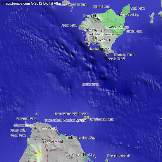
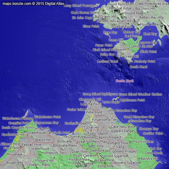
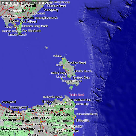
Not meaning to be a smart-ass Oscar, but out of fairness to the OP, that area is Banks Strait, not Bass Strait, named for Joseph Banks the Botanist, as I understand it. I think Bass Strait is the part north of Flinders Island and Banks Strait is south of Clarke Island.
-
I agree that a paid subscription to a site like this would be an ideal solution to alleviating the associated costs for the developer. However, just in my meagre experience with forum sites in general, it's been demonstrated quite a number of times that it just doesn't work. Some of the most populated forum sites have software and general infrastucture, features and facilities that have barely changed since those sites were first established, and that doesn't appear to affect their popularity significantly. Certainly this site provides a pleasant user's navigational experience but the actual written content is still entirely dependent on the contributors, not the software. The two main considerations are - The site infrastructure has very little influence on the quality of the information on the site or on the number of people that frequent it and/or post on it. Having a lot of up-to-the-moment features and facilities on the site may suit some of those who visit but as I understand it those who most often return to a site generally only use one or two of those features. I might be a reasonable example of that, I know there are a lot of things on this site but I hardly ever look at anything other than the 'New Posts' page. There is some great stuff amongst John Brandon's tutorials and I refer to them sometimes but there are several other site features here that I've never looked at. I'm sure this Expo thing will be a fantastic feature too, and no doubt I'll look at it to see what it's about but only time will tell whether I'd look at it again after that first time. If it's to showcase aviation products and aircraft available on the market I'd be more likely to visit the products' own sites I think. That's just me of course, other will doubtless vary. The second consideration, when expecting all site visitors or users to pay a subscription, is that all those using the site 'ain't equal'. I do pay a small voluntary subscription to three sites and the amount I offer is based on the balance of how much I feel I get from the site and how much I feel I contribute to it in the value of what I post there. Consider - if no-one posted on a site and everyone just went there to read what others wrote - well, if no-one posted there'd be nothing to read so the site would be worthless, wouldn't it? People only go to a site to read what contributors offer, and some of them offer their own (written) contributions, many don't post anything at all, or very rarely (I'm talking generally, not about this or any other site in particular). One of the sites to which I contribute a little cash continues to provide me with valuable engineering and aeronautical design information that I would be hard-pressed to gather elsewhere. I contribute a little knowledge there too, but the balance is in my favour, so I make up what I feel I owe with a small cash contribution. I really enjoy interacting with people on this site, and particularly it being an Aussie site, so I gain a lot from that. I also feel that I contribute a lot by sharing the engineering and aeronautical knowledge that I have gained by personal experience and by research over the last forty years or so, so I hope that I pay my way here, without being forced into making a compulsory cash contribution as well. Then the question would be - how would you determine those who gain more than they give, compared with those that give at least as much as they gain? Could you look at the 'likes' perhaps? That wouldn't work either - even if you compare the likes:posts ratio it still tells very little. There are contributors who have very high likes tallies but have never contributed anything much of real value to the site because they only post jokes, and mainly off-topic at that. Then there are pseudo trolls who have a high likes rating because they have a cult following of similar non-conformists. There are contributors with a clever sarcastic wit who don't even fly, and some who simply post stuff gathered from the net. The issue of cost mitigation or even of using a site like this to make a positive income is indeed a very vexed one, and certainly not easy to do successfully. Further than that, it's well known that whilst not impossible, it's very hard to make a living from anything to do with aviation. This site has certainly done well in bringing more people into the fold, Ian is to be congratulated for that, he said he'd take it international about a year or 18 months ago and we certainly have a good percentage of overseas contributors now. Other sites make their primary income from straight-out advertising so that's probably the way to go and if sufficient numbers of exhibitors on this expo feature can be persuaded to part with US$250 to US$600/month to cover the $3300 rent and hosting plus a profit, then I guess that would be a goer too, but if not it could be a heavy burden. I'm imagining the everyday site user would have to go to a specific part of the site to view these expo booths, the question then is - would they do that? At least with on-page adverts they're staring us in the face as we read the 'New Posts', so they must have some subliminal influence. So I guess the question would be - would the expo booths be able to have a similar presence on the New Posts page, to encourage site visitors to look at them?
-
A few days ago a very significant historical aircraft event took place. The restoration of the only existing propeller driven WW2 aircraft prototype - that of prototype No.1 of the de Havilland Mosquito - was completed and rolled out of the main hangar doors of Salisbury Hall, 75 years to the minute after it first did so in 1940. For those who might not know, in 1939 the stately home Salisbury Hall near London Colney/St Albans to the north-west of London became the top secret 'skunk-works' of de Havilland Aircraft and is where the three Mosquito prototypes were built. My family has a particular attachment to the project because my grandfather was the head foreman of the toolroom and 'lived-in' at the Hall for some years during the war. He was responsible for the build and for developing the production tooling when the fight testing was completed. It's humbling to think that he would have played such an active role in the original event that is seen being re-enacted in the image below. Here is a link to the Wiki article about Salisbury Hall. A link to the fabulous De Havilland Aircraft Museum which is now located in the grounds of the Hall. Following is a description from Philip Birtles of the restoration roll-out which took place a couple of weeks ago at 14:45 on 25th November - Mosquito 75th Anniversary, 25 November 2015. As planned some four years ago when the Mosquito Prototype was dismantled and moved out of the Robin hangar, the restoration and conservation was completed in time for the 75th anniversary of its first flight from Hatfield by Geoffrey de Havilland Jnr. It returned to Salisbury Hall, where it was created in 1940, and was opened to the public on 15 May 1959, the first aviation museum in Britain, then known as the Mosquito Appeal Fund. Assembly of the Prototype, the only WW2 propeller driven prototype to survive the war, commenced in February this year when the fuselage was lowered on to the wing. The event was attended by invited guests, with the Lord Lieutenant – the Countess of Verulam representing our patron, the Duke of Gloucester, in addition to the Lord Mayor of St Albans, the Lord Mayor of Hertsmere and the High Sheriff. At 14.45 hrs precisely, the time the prototype took off from Hatfield in 1940, the hangar doors at the Museum were rolled back revealing the Prototype which was pushed out by the restoration team, amidst smoke, floodlights and the theme from 633 Squadron, just like an Airbus media launch. The following day the exercise was repeated for the benefit of members and veterans, and although the Museum has closed for the season, it was opened to the public on the Friday, Saturday and Sunday, when some 800 visitors came to see the Prototype and the other two Mosquitos. Mosquito W4050 25 Nov 2015 - courtesy PJ Birtles .
- 8 replies
-
- 14
-
-

-
Y Yup, in that respect it's exactly like the Piper Pacer and Tripacer. Historically there have been many Tripacer nose legs for sale. So - given that pilots of tri-gear planes regularly wipe out the nose leg, from the Piper example it's probably safe to assume that most Tripacers got converted to Pacers rather than the other way around. Which indicates that folks who become competent with a nose wheel would probably be happier with a tail wheel eventually, so if you're considering a kit you could save about US $1500 probably, by bypassing the nose wheel stage altogether ...?
-
Que? How new is new FT? I was talking to Matty metalman when he flew up here a year ago and he was thinking of buying a Raven kit then ... I had a look at it at the time and it was a dragger - I couldn't imagine metalman in a tri-gear ...
-
The S20 certainly looks slick but the S7 would be sleeker, I would think. They're both two seaters, the 7 is tandem and the 20 is side by side, so the 7 is much slimmer.
-
Yes - when I was instructing it was interesting to watch the development of our students as they matured once they left the nest. It's a generalisation of course but there were three very noticeable milestones - up until 100hrs most were meticulously careful and showed pride in doing everything 'by the book' and keeping the training close to mind. After 100hrs many became a little more brash and tended to show off a little to the 'newbies' and became a little slacker with their procedures and discipline. They occasionally gave themselves a scare which brought them back into line temporarily. The '500 hour syndrome' was the biggie - by that stage many of them knew everything, could do anything and were bullet-proof, whenever they looked in the mirror anyway ... By the time they reached 1000hrs many had had enough scares to realise that learning never stops and we're all vulnerable, the less we think ahead, the sooner will be our next big wake-up call.
-
Oscar beat me to it while I was typing ... The aircraft being offered for sale above must be the original prototype of the Rouseabout, because it certainly isn't one of the production models. For those who may not know the history, the Rouseabout was a development of Gordon Bedson's Resurgam. Gordon designed the Resurgam way back in 1948, believe it or not, and in the early 1980s offered plans with a minor components kit. About 40 were completed by late 1983. By that time Gordon was working with Don and Peter Adams of Geonic Aero Industries, Woodridge (Geonic was the Adams' company before Seabird Aviation of Hervey Bay, who went on to develop the Seabird Seeker much later), to develop a much more sophisticated version of the Resurgam which became known as the Rouseabout. The production Rouseabout, however, had an all-composite fuselage, and it was quite advanced composites for the time, making a lot of use of Kevlar. The wing ribs, tail surfaces and D nose were all composite also - it was a nice thing! The one offered for sale above is not a Resurgam, but neither is it much like a Rouseabout. Berger-Burr's states that the prototype Rouseabout had a fuselage with "an aluminium sub-frame and tail-boom, but production aircraft are expected to be of carbon fibre/Kevlar composition with an integral tail boom", so presumably the one that's for sale is the original prototype of the Rouseabout, in which case it dates back to 1984 or earlier, because Gordon was killed on the maiden flight of his two seat Magra in 1984. Below is a scanned picture of the production Rouseabout with Don Adams at the controls - courtesy of Berger-Burr's "Ultralight and Microlight Aircraft of the World" 2nd Edition 1985/6 - Interesting bit of history flyvulcan - must be great to look back to those early days and see how far you've evolved, now flying Bizjets to all destinations around the world
-
Why does aviation still use imperial system?
Head in the clouds replied to RDavies's topic in AUS/NZ General Discussion
A bit earlier FT asked about wire gauges and people have spoken about the merits, or lack of, of the various thread-forms (which are widely misunderstood). On other forum threads the reasons for the use of different materials, fatigue, metallurgy, drills, drilling, cutting edges, all sorts of matters that have direct relevance to our sport are something of a mystery to many of those of us who participate. For those who seek to learn about all this and much, much more, there is the Machinery's Handbook. It is the 'Bible' for Mechanical Engineers, Draftsmen, Toolmakers and Machinists. It has been published continuously for over 100 years since 1914 and gets bigger each year. It's now on its 30th edition. Interestingly it's getting cheaper, when I got my first one about 35 years ago it cost $140, now it's about $70 and you can get used ones for under $60 from Amazon. Occasionally you can pick up a good used one from a second-hand book shop for $10-20 if you're lucky. My first two got souvenired by people who must have needed them more than I did, so currently I'm using one passed on to me by my old toolmaker mate Bazza who passed away last year. It is the nineteenth edition and was printed in 1973 and has 2500 pages. Newer ones do have a little more information in them (the current edition has 3000 pages) but the older ones have almost anything we'd ever dream of needing or wanting to know about, so don't pass it up if you spot one on a dusty bookshelf. I've posted a few pictures below which show the Contents Headings, if you can read them in the images.
-
You have been told - by kevin walters
Head in the clouds replied to Tomo's topic in AUS/NZ General Discussion
There's a small thing you can do which may well significantly increase your chances of a good outcome in event of EFATO. It used to be taught to all GA trainees, but for a different reason. I've always continued to use it particularly when flying any front firewall-mount engined plane, even when they're LSAs or ultralights. On climb-out we were taught to lower the nose each 500ft so that we could see over the cowl and check for traffic before resuming the climb. However I noted that many pilots didn't continue with that practice once they had their licence, and I can't recall ever seeing any LSA/ultralight pilots doing it, probably because most are tall enough to have a reasonable amount of vision over the smaller cowls of LSAs. Perhaps I've always done it because I'm shorter than most people and so I probably see less over the cowl than most do, even in a Foxbat or Tecnam, even with their relatively low instrument panels. Since I've retained the habit I also use it to help me prepare for an outlanding in event of EFATO. In fact on the occasions when I have had EFATOs under 500ft (2 of) I've not even considered turning back because I'd already located my outlanding spot, so I didn't have to think about lowering the nose, or which way to turn to get there. Because of their lower momentum, and particularly at an airfield that I'm not familiar with, in an LSA I lower the nose each 200ft until I'm above 600ft, then each 3-400ft or so. If there's any crosswind at all straight after lift-off I allow drift downwind from the centreline wherever possible, to improve the turnback situation should I get high enough to do so, and I first look for a suitable outlanding spot anywhere within 90 degrees to windward. Once I have drifted sufficiently downwind I then allow crabbing into wind which reduces the amount I would actually have to turn if I needed to use the outlanding in a hurry. After I've reminded myself of my intended EFATO actions pre take-off, I can't say I really give any of it a lot of conscious thought from then on except very frequent checks on Ts&Ps. I find the lowering of the nose for a look-see prompts the other actions - it works for me anyway so I'd recommend it if anyone is doubtful about their EFATO performance. -
Why does aviation still use imperial system?
Head in the clouds replied to RDavies's topic in AUS/NZ General Discussion
Actually, no. The French Academy of Sciences chose the first definition of the metre from a choice of the Paris/Pole/Meridian method and the pendulum method way before then, in 1791. The new platinum/iridium definition came from the BIPM nearly 100 years later with the '1874 Alloy' revised again five years or so later and adopted at the CGPM (General Conference Weights and Measures) and revised again about forty years later to make a small correction. The Alloy definition was then replaced in the 1960s with the all-new Krypton wavelength definition and then in the 1980s it was again replaced with another completely unrelated definition, this time the distance of light travelled in a vaccuum in a specified period as I mentioned above. Not that any of that really matters, except to demonstrate that the metre is not something that's ten, or a tenth, of anything else, so it, itself, is not a metric quantity. The Germans are exceptional engineers, both structural and machine. To paraphrase a well known engineer's creed - 'if you are ever unsure about your design, just ask yourself "would the Germans do it that way"'. However their excellence may rather be a case of 'despite the metric measuring system, rather than because of it'. While in Africa, and also in Australia I got to know a lot of ex-patriot German engineers, toolmakers and machine, and without exception they work using the imperial measures rather than their native metric - YMMV of course. The Russians may well also have been at something of a disadvantage using metric for machining measurement. Other than in very specialised areas like their early space program it took their general industry longer than most developed nations to establish reasonable universal precision. For the most part they built bigger, heavier and stronger but much less precisely. -
Why does aviation still use imperial system?
Head in the clouds replied to RDavies's topic in AUS/NZ General Discussion
Sorry dutch, but your irony is misplaced. The inch isn't otherwise divided into anything except by individual choice, you can fraction it into anything you like, tenths, halves, quarters or even sixths if it serves you best. Your argument may apply if you were talking about feet or yards or miles being divided into smaller parts using the base ten, but it's perfectly correct to divide inches decimally where it suits. Similarly, the metre isn't, itself, a metric unit, although it was once defined as a metric division of the distance from here to the sun and later a metric division of the distance around the equator, IIRC, since 1983 it has been "the length of the path travelled by light in vacuum during a time interval of 1/299 792 458 of a second". So - that particular length, itself, isn't metric. The metric aspect only begins when we divide or multiply it into lengths using the base ten. In that sense it's no different to doing the same to the inch, except the inch is far more appropriate a size where machine engineering is concerned. -
Why does aviation still use imperial system?
Head in the clouds replied to RDavies's topic in AUS/NZ General Discussion
That's interesting - I've experienced almost the opposite. I provide a drafting service for both construction industry structural steel, which is fabricated by boilermakers, and precision machining drawings for toolmakers and general engineers. The standard overall tolerance requirement for structural steel is plus or minus 2mm on any individual member or fitting of a structure, so the metric system works very well for steel fabricators and many other welded, riveted and/or bonded structures, most automotive coachbuilders and cabinetmakers, for example, work to plus or minus 1mm, rather than 2mm. Machining is quite a different matter and just about all the old fellas use imperial and I know many of the young brigade, who were only taught in metric at college, who also use imperial wherever possible. The reason behind that is that the metric system doesn't work well with required fits for most medium and high precision machining. A tenth of a millimetre is very close to 4 thousands of an inch and that is not nearly a close enough fit for almost anything except some of the cheap Chinese gear some may buy. A hundredth of a millimetre is 0.4 thousandths, or "four tenths" as a toolmaker would say (that's four tenths of a thousandth of an inch). Given that the most precise machining requirements I ever detail is for an accuracy of two tenths (with a tiny tolerance) and the usual range of fits is between half a thou and two thou, you can see that in metric we need to be specifying figures like a two hundredth of a millimetre (rather than a hundredth - or 0.005 rather than 0.01) and then the range of an eightieth of a millimetre to a twentieth of a millimetre (0.0125 to 0.05) - so, regardless of being a metric system machinists still have to work in bases that are rarely ten ... CNC machines take the thinking and need for conversion away from the human machinist in many cases but they're still working odd fractions, even when scaled or programmed in millimetres. Not only that but just as some pilots may confuse fuel loading in pounds when it should have been kilos - you should see the number of precision machined parts that end up in the scrap bin when a CNC machine (or human machinist) is set to 0.05 instead of 0.005 - that's when the difference between the imperial "2 thou" and "half a thou" seems to be more readily understood. Perhaps it's easier to perceive the actual size that way, than to recognise the number of zeros in the metric equivalent. Drilling, tapping and reaming is similarly easier in the 'old system' - you seem to need far fewer to get you there if you have a full set of imperials in 1/64th increments and a set of number and letter drills, than if you have metrics, even in 0.1mm increments - even if you can afford them all. -
The theory's good Nev, but in practice it doesn't work. I've tried quite a number of them and the 'powered item' just isn't heavy enough unless it's a golf buggy or ride-on mower or similar. Those purpose-made minimalist aircraft tow-carts weigh around 30-40 kg and if you just try and use them to tow their wheels just spin and you go nowhere. Of the two I posted pics of - with the first one you bear down on the handles and that lifts the nose-wheel off the ground, transferring the nose-wheel weight onto the wheels of the tow-cart, and additionally the weight you bear down also transfers onto the tow cart, only then do the wheels of the tow-cart have enough weight on them to gain traction. On a smooth hard surface you can reduce the downward load on the handle and let the nose-wheel onto the ground again, bearing down just a little if and when the wheels spin, to have a portion of the nose-wheel weight assisting tracting. The second one has a platform and you rest the nosewheel onto it to get the extra weight to provide traction. I tried each of those types on my C172 and the second one didn't work on grass or gravel or a slope, the wheels still just spun except on a level hard surface. The first one actually gets much more benefit from the applied weights because of the leverage provided by lifting the nose-wheel on arms and from the length of the steering handle.

.JPG.e140c9dcc78882cd43ee93a691a9fca7.JPG)
.JPG.92bb444e06f79a0e08c611334f18d4ca.JPG)
.JPG.8262710f385bd768d28f38fa8127abf1.JPG)
.JPG.d6092f72fb8716ef4a1c27bfe24c287b.JPG)
.JPG.3a499203b72e9077bc735281f65ce249.JPG)
.JPG.78c7fd8b4c8df4fbe5efbd479bbff62b.JPG)
.JPG.77f609f2544ad7f2f5ab2ecffd2f75a4.JPG)
.JPG.d8571b1846f3e542c7f4ce2b53867cf3.JPG)
.JPG.5783e991234ca23c1ab2232181d9bcb1.JPG)
.JPG.c6c6f2f598b9f8a936a53edb98de0406.JPG)
.JPG.e1b51c5429fe57068feb670430fa660c.JPG)
.JPG.9976f09c65e2d17031730be1e7a4b6a6.JPG)
.JPG.720f84246987ed529103ba1e30b89749.JPG)
.JPG.ded2eaaebda32dec5016976d9f8d3413.JPG)
.JPG.41b8f5eb5309f41e317f761125423e13.JPG)
.JPG.0581b018ff1f6d8be7650836d3f08d69.JPG)
.JPG.0f7fa2cbb7a95a895d9b95558d4baccd.JPG)
.JPG.a5e7e1bab553f9698c1cb6e740d85711.JPG)
.JPG.0fd923105b279435333ed7bba985d83d.JPG)
.JPG.4942a709667c0113d6a498dd6dbd842e.JPG)
.JPG.9dc47ec3049b0a28f0aaac1b9faf53c7.JPG)
.JPG.8fce199d473a28d41f9262bd28b89b42.JPG)
.JPG.1ef3b111b2728355522f40cfe624066f.JPG)
.JPG.b82d58338e82ff652dc6a7e33df43330.JPG)
.JPG.cf38ee21594342fab5e6c8a798707b90.JPG)
.JPG.5ce31af275c85deaca22cdc357194578.JPG)
.JPG.0b8b8fc47a0b3b117305a3f2704438c8.JPG)
.JPG.e2c5dbdcf852fc83788122cae8c12e11.JPG)
.JPG.6c8ff88284c1f2a0875abaf6c0aac9d4.JPG)
.JPG.fc79216dfc910478b5b025a5d19a673c.JPG)

.JPG.31faa9efc142c87dd269e28f7fdaf247.JPG)
.JPG.5faa81a0a0834013bab541811285a898.JPG)
.JPG.bc6def01acd7aa5ed59ac9fcf6974058.JPG)
.JPG.f9323d32ccb62bcb9955e174b722bf66.JPG)
.JPG.f79a1cad964720a272e0ac05e0ae1bdf.JPG)
.JPG.b46d6fd9522264ec5b89bf15dfd501a1.JPG)
.JPG.c19be96f4e9a709353049f9a45a52df8.JPG)
.JPG.ee3fbdb861c3794e425b2a84648a10bf.JPG)
.JPG.b9088450ce79656b9825e20ece2abca0.JPG)
.JPG.9d8814fc5dfe91a62ed821dacda4e88b.JPG)
.JPG.4e2391944d7bb1dc7d63f9fab2aaa7d2.JPG)
.JPG.1ef02cadb9e75cdaa20637b1576c699f.JPG)
.JPG.2738629fe89bfadba1e311684ed12caf.JPG)
.JPG.848b7b3011157b77fa9f14b8c2533217.JPG)
.JPG.84f0a42693b7bc4f538e241cc198235c.JPG)
.JPG.24079d58c5f6bd5bc8979f6d0d327b56.JPG)
.JPG.3ad9dc4994555fad4cc7000f424f9025.JPG)
.JPG.ea95fe20707f3d30ba5381f6a170870d.JPG)
.jpg.878090ac8039b0247b8cb8be305f1cac.jpg)
.JPG.ea91d80f9e36c74417dfa5b5d78793c3.JPG)
.JPG.7e18177099c98c4e9d1ebefcb70396b3.JPG)
.JPG.85ab5f30cda705018d48e5c9758fe98b.JPG)
.JPG.98da43d6f5106cfa234cc297b59ee619.JPG)
.JPG.027019774d4cc19ad6048e8dc781f671.JPG)
.JPG.1894a976edb8478f2f70004447cd0f7d.JPG)