
Head in the clouds
-
Posts
1,842 -
Joined
-
Last visited
-
Days Won
42
Content Type
Profiles
Forums
Gallery
Downloads
Blogs
Events
Store
Aircraft
Resources
Tutorials
Articles
Classifieds
Movies
Books
Community Map
Quizzes
Videos Directory
Everything posted by Head in the clouds
-
Aircraft down Lancefield Vic
Head in the clouds replied to red750's topic in Aircraft Incidents and Accidents
Well if you're going to have 'some sort of info/checklist, presumably the info would be what you'd normally find in a POH, things like critical airspeeds, fuelling info, W&B, emergency checklist etc, so why not then call it a POH and have done with it? OK, "just to keep CASA happy" was probably a poor choice of wording. What I should have said was "to show CASA and other interested parties that we are willing to be just as professional and responsible as other airspace users". Belligerence for the sake of it doesn't help our image one iota. It's all very well sport pilots getting uppity about conforming to what everyone else is doing in the air but there are powerful factions that would have it that we're a bunch of cowboys with poor or limited knowledge of the regulations sharing the airspace with essential services and RPT, and who should either toe the line or be excluded altogether. -
Aircraft down Lancefield Vic
Head in the clouds replied to red750's topic in Aircraft Incidents and Accidents
Well I'm not completely up to speed on Recreational/sport aviation requirements as I've been commercial GA for so many years and just getting back into the sport side of it, so I'm probably not the best to answer this - BUT as far as documenting the daily inspection goes - earlier there was comment about 'should we have (or perhaps it was carry, can't remember) a maintenance release'? As yet I'm not sure what the requirements are for maintenance releases for privately owned 95.55 aircraft that aren't certificated or being operated for commercial gain (flying schools and renting out planes etc). That's not to say the rules about that are difficult or confusing, I just don't know because I don't need to know because I don't have a flying 95.55 yet ... but when I do, I will know ... However, when I hire a plane on occasions to keep current, I rent it from a school and they keep a maintenance release and I check that it has been signed off for the DI, regardless that I always do my own comprehensive DI/preflight anyway. And - regardless of what it turns out the rules actually require, and regardless that it'll be private, not certificated and not for commercial use, when DooMaw is flying I'll be keeping a maintenance log and signing off the DI in that. It's amazing how useful a document like that can be in event of anything going wrong quite apart from the very process of signing off DIs and such being a very useful tool for establishing personal discipline about the maintenance and inspections which, in my mind and experience, are a critical part of flying more safely. If a plane has never had a POH, I really don't know what the regulatory situation is, but some of the RAAus operational documentation requires reference to the POH in certain situations, and if there isn't a POH, how can the pilot comply with the requirement? I wouldn't have thought it'd be a very arduous task to write a POH, especially for an aircraft that someone knows well. In any case it might be a very helpful thing to have as an 'aide-memoire' particularly if one was under pressure perhaps? Not only that, but even if there is some reason whereby, under certain circumstances, a POH doesn't absolutely have to be provided (for example perhaps owner-built aircraft built prior to x years ago), I think some CASA inspectors at ramp checks might find it 'odd' that some people/planes are flying around without a simple book of basic operational instructions and limitations. If for no other reason than that - just to keep CASA happy - I'd write one up for DooMaw. And - since I'd be writing it, it'll be very short and succinct, and wouldn't limit anything that isn't actually dangerous. For instance it'll have brief details about things like how to mount external cameras anywhere I might like them ... that should stop a few pointing fingers in their tracks. -
Aircraft down Lancefield Vic
Head in the clouds replied to red750's topic in Aircraft Incidents and Accidents
I don't quite understand where you're coming from ... The ramp-check check-list tells you what to expect and the references provided at the bottom tell you what legislation requires you to do it. You may, or may not, have to comply with every part of the legislation, depending on the type of flight you're conducting on the day (category of aircraft, distance from departure point, weather etc) but I think it's perfectly obvious which parts of it are relevant and when. Note that the check list is for sport aviation in general and that might be different for VH reg sport planes/pilots, gliders, LSAs, 95.10 etc but hopefully the pilots of each different type have enough understanding of the airspace regulations to know which of it applies to them? If not isn't it time they took a refresher course at the next BFR? Which part of it do you think isn't relevant or "not what CASA sez you must do"? -
Aircraft down Lancefield Vic
Head in the clouds replied to red750's topic in Aircraft Incidents and Accidents
The CASA ramp check guide I've seen looks quite relevant and understandable - copy/pasted below - And there's a handy pdf you can print out as a check-list that you can access by clicking the link at the top of that page - or here, I'll also try and attach it below ............................... I’m a Sport pilot and have been selected by a CASA inspector for a ramp check What happens now? I’m a Sport pilot and have been selected by a CASA inspector for a ramp check The inspector will ask you for, or confirm, your pilot certificate and other relevant documentation You should carry your pilot certificate with you when you fly. However, some sport organisations may have different rules, so check your organisation’s operational manual or regulations. It is also suggested that you carry a copy of your log book page with last flight review. Current/valid RAAO membership Aeroplane operated in accordance with the privileges and limitations of your pilot’s certificate Correct endorsements for flight You must carry your current aviation medical certificate if applicable and you must be compliant with any restrictions or endorsements on your medical certificate or driver’s licence (e.g. the wearing of corrective lenses). The inspector will then check your preparation for flight Flight plan Have you maintained a navigation/fuel log? Have you made a careful study of forecast weather and applicable NOTAMs? ≥ 50nm from departure point ELT/PLB required for two-place aeroplane If carrying a passenger - passenger endorsement ≥ 25nm from departure point – cross country endorsement Are you carrying the appropriate, current charts and documents? Are they easily accessible? Are you carrying an EFB for your charts and documents? Back-ups considered? Finally, the inspector will check your aircraft The inspector will check: The aircraft’s registration is current Condition of the aircraft The daily inspection Pilot’s operating handbook (POH) or flight manual Emergency checklists Warning placard if applicable Copy of CofA if applicable Aircraft has a placarded maximum take-off weight in accordance with the flight manual Aircraft is operated within weight and balance limits Required emergency equipment on board is serviceable and accessible if applicable Personal locator beacon (PLB) has current registration with the Australian Maritime Safety Authority (AMSA) Document references Operations manual CAO 95 series as applicable Operations Responsibilities of the pilot in command before flight – CAR 233 Planning of flight by the pilot in command – CAR 239 Navigation logs – CAR 78 Fuel requirements – CAR 234 Weather and NOTAM – CAR 233 & AIP ENR 1-10 paragraph 1. EFBs – CAO 82.0, CAR 233 and CAAP 233-1(1) Aircraft Checklists – CAR 232 Emergency equipment – CAR 252A (two-place aeroplane only) *Regulation details current as of December 2013 ramp-checks-sp.pdf ramp-checks-sp.pdf ramp-checks-sp.pdf -
DooMaw - building a STOL
Head in the clouds replied to Head in the clouds's topic in Aircraft Building and Design Discussion
April 8-9th 2016 I modelled the rudder cable guide pulley hardware in CAD, produced the drawings of the plates, spray-paint templated and cut them out. That took a whole day, it's a time consuming business cutting out, drilling and deburring these small plates by hand. However the only other option would be to fully complete the CAD model of the design before starting any of the build and then the plates could all be cut by laser. The down side of that is that it would have taken about another year of design work to do, so I would only now be starting the actual build. Since I do the building rather than the CAD work for relaxation, I'd be even more bananas by now, than I already am. Also - the design has developed because I've had time to think about it while fabricating the fuselage frame, so it's a better design now than it would have been if I'd done all of the CAD work beforehand, one always discovers improvements along the way. There's nothing stopping me getting the plates laser cut as I go along, of course, except it's not cost- or time-effective, the laser people don't like doing really small runs so they charge a large price premium, and also there's a fairly long lead-time, usually 2-3 weeks, so I'd be held up a lot of the time. Anyway, cutting them by hand saves a few dollars and means that at the end of the day more of the plane is hand-built than it would otherwise be. Below are a couple of images from the CAD showing the design development, note the large angles at which the pulleys have to be set to properly align the incoming and departing cable. Unless these angles are set accurately it results in very rapid wear of the sheaves - they are made of Tufnol and have quite a long life if well aligned, but can chew out in 100hrs or so if not, and they're not cheap so you don't want to be having to replace them more often than necessary. I also made up small tubular spacers so that the pulley bushes run on them rather than the central bolt, and that allows the bolt to be done up tight against the spacer. That way the bolt can't turn and wear the holes in the clevis plates. Then it took all of the next day to weld them in. As I've mentioned before, it's not the welding that takes the time but achieving the setup. Developing ways of holding these little mongrels 'just so' while getting them tacked was quite exasperating. Actually I didn't weld in two pairs of them because I realised that they are in the space where the strut attachments also fit, so I needed to complete the design of those plates first, to see how they'll all fit together. Once that was done I went back to modelling, and developed the strut attach plates - 17hrs in that, taking the total over the thousand hour mark - to 1008hrs
-
You probably recall these quotes anyway Kaz. IIRC Dafydd went on to tell the tale of the fella who used to tow gliders with his Auster and was sure he used to land at about 30kts, but when Dafydd fitted it up with a calibrated ASI, swivelling pitot and trailing cone static I think he said the stall was about 40kts and the landings were actually at 48kts. I can't find the post unfortunately.
-
Hey Russ, I'm sure you're going to have a ball. Your track is a virtual replica of a trip I did about ten years ago in my C172. It's pretty straightforward flying regarding out-landing opportunities, except the legs that get you from Musgrave to Weipa, I have to admit I didn't like that bit at all but perhaps it was just the conditions on the day, yours may well be different. I went in September IIRC and it seemed that every Aboriginal owned station had decided that was the best time for firelighting so the vis was extremely limited for a lot of the time, large swathes of ground just disappeared under a blanket of smoke. In some ways it wasn't too bad, because the bits that were visible weren't landable anyway, long, long stretches of trees and rugged ground. Also had 4/8 stratocumulus at about 3500 most of the time so it was a constant toss-up between going under or over, I chose over for the first half then it became about 6/8 and the gaps were too small to get down at the destination, so the last part was under, it was 'pleasing' to see Weipa in the sights eventually. At the time I recall thinking that if I do the trip again I'd follow the State Development Road to have more out-landing opportunities available. Weatherwise the other 'moment' on the trip was returning Horn to Cairns, around Lockhart a stream of cloud tracking West-East and developing fast. When I first saw it I decided to go over it and commenced a cruise-climb from about 30 miles before it. At ten miles before it I could just see the horizon over it and was at 9000ft. There was no going under it as it was black-as underneath, and on the deck, and the only lower cloud tops were well out to sea, perhaps 15-20 miles offshore. I had to orbit and climb for a while and scraped over the top at ... well better not say on here, but it was 'quite high', highest I'd ever been in fact. Just at the apogee I was passed quite close to starboard by the QANTAS-LINK F27 that had left Horn 40mins after me, also bound for Cairns. We knew each other were there - we'd been chatting. At Cairns I caught up with the QL crew and they told me that cloud-stream was a regular feature and the only way to be sure of avoiding it was to leave Horn at sparrows. I don't know if they're still there as I haven't been in touch in a long while but I can recommend - Craig and Nicole Jenkins run a fly- and sports-fishing operation called Strikezone in Weipa (07) 4069 9880 Bill Ennis ran Fishing and Marine Charters on "Karumba Miss", also out of Weipa 0428 697 232 or (07) 4069 8276 www.weipa.biz/6816.html There's a shuttle-bus meets the QANTAS flights on Horn and takes you to the port - it's way too far to walk. From the port there's a ferry to Thursday Island which is really lovely but expensive. Book accommodation ahead if you want it, they're usually full. The Kazu Pearl shop in the main street is a must see and if you're into pearls you can buy them at 25% what you'd pay elsewhere. Mariko Tatsuzawa has owned and run the shop since time began, she may still be doing so. Kazu Takami owns the pearl farm that supplies it, he's a lovely man and fascinating. If you want a 'real' piece of the area you can arrange a trip with him if he likes the sound of you - unofficial trip, he doesn't run 'tours'. His pearl farm is on the waters around Friday Island and he knows places that no-one would find without the local knowledge ... he's hard to get hold of, but worth the effort, the TI factory is (07) 4069 1268, Cairns Office is (07) 4033 1988 [email protected] The above was all ten years ago so apologies if any/all of them are no longer available. If you haven't been there before Cooktown is terrific for those of us who love the more out-of-the-way towns and it's full of colourful characters of course. Princess Charlotte Bay was the big disappointment for me but then I'd previously seen plenty of mud-flats. The reef is way offshore and the mud-flats are just croc infested ooze with sporadic mangroves. Rustically colourful at the right state of tides though. Would be much better on the ground, especially for crabbing. EDIT - actually a quick Google indicates that perhaps Kazu Takami does have tours of his pearl farm but I wasn't meaning that, I was meaning him taking you fishing, which could be around Friday, Wednesday, Goods or any of the other islands.
-
After an initial burst of activity and mega publicity about three years ago, the prototype FlyNano performed one test flight that appeared to be none too auspicious with many of us suspecting that it ended in a crash because their published video only showed the take-off and climb to about 15ft and then faded out. Despite numerous requests to the factory for more information (I know there were numerous, because I made lots of them myself ...) they declined to issue anything more except to say further testing was on hold due to the lakes being frozen in Finland. As the years wore on it was assumed by most interested parties that the project had died despite the obvious large amounts that had been spent on initial development and the impressive publicity machine. Gforce on this forum said he was the Australasian distributor and also mentioned that they were still going ahead with the project though he couldn't offer any details. Out of the blue after nearly three years, and as a 'signed-up member' of their mailing list, I received a communication yesterday with a link to their new video which reveals much more information about their progress than previously, including film of extended flights with gentle turns and a landing. They've obviously been beavering away in secret because they have an all-new airframe that looks very smart and which dis-assembles into three major components for transport, and an all-electric powerplant. It's well worth a look - [MEDIA=vimeo]141518328[/MEDIA]
-
Sure, autonomous drones are available, whether to call them expensive or not is in the eye of the wallet holder ... and then there's autonomous and there's autonomous. A simple 'so called' autonomous drone that costs around US$1500 seems to have a max flight time of around 5mins which isn't really time to go very far or do much, whether of a friendly or a nefarious nature. When you start talking about 'proper' autonomous drones with long flight-time capabilities (5-50hrs) you're going to be spending something more like US$25K to US$40K for production machines and anything upwards of US$100K for custom built machines, so they're not cheap in anyone's language. As far as Australia is concerned, though, autonomous drone flights are completely prohibited except with a special CASA Approval on a case-by-case and flight-by-flight basis. As far as I have been able to determine, for the foreseeable future all drone flights have to be flown by a pilot and flown within visual line of sight. This does allow the flight to be conducted by FPV via video streaming however the craft then has to be in visual line of sight of a spotter who can immediately take control, not higher than 400ft AGL etc, all of which considerably limits their practical usefulness here, regardless of whether it's with good or bad intent. Given that autonomous drone flight is illegal in Australia (except by special Approval) those considering buying drones with autonomous capability need to maintain a healthy degree of 'emptor caveat' lest those products suddenly end up on the prohibited imports list and subsequently get confiscated ... The definition of 'autonomous flight' as given in Airworthiness Circular AC101-1 is - Autonomous Operation: A pre-programmed, automated flight profile that does not require human intervention for normal operation. Presumably this would technically include drones with the 'follow' function being used as autonomous 'selfie sticks' - though CASA seems not to intend this to be the case if I correctly interpret the rather unclear interview with CASA by The Australian last year (assuming CASA was quoted correctly by the media) - The Australian spoke with CASA about new, autonomous drones on show at last month’s Consumer Electronics Show that can be preprogrammed with a flight plan to fly without being manually piloted. CASA said these drones could be flown legally provided the piloted was still in control. “Fully autonomous flights are still some way off,” the spokesman said. “Current technology enables users to pre-program a specific route. But this kind of flight is by no means ‘autonomous’, as the operator is still required to pilot the aircraft over the designated route. ...... There is rapid change taking place regarding drones and their regulations, so no doubt we will hear of more developments in the near future.
-
DooMaw - building a STOL
Head in the clouds replied to Head in the clouds's topic in Aircraft Building and Design Discussion
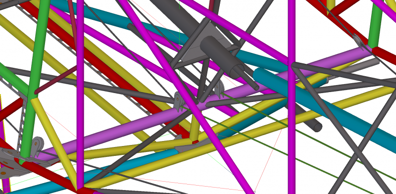
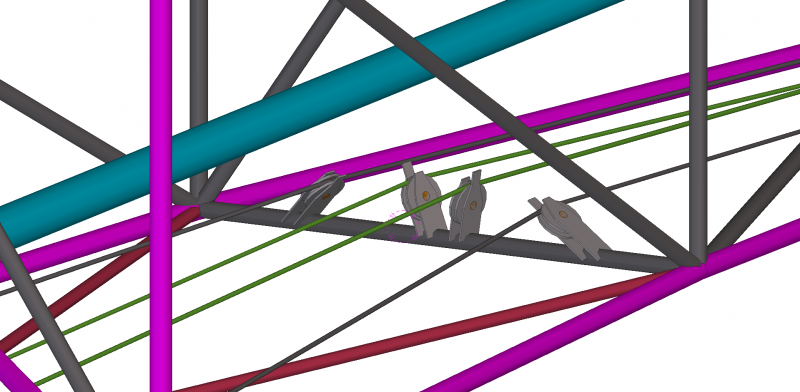
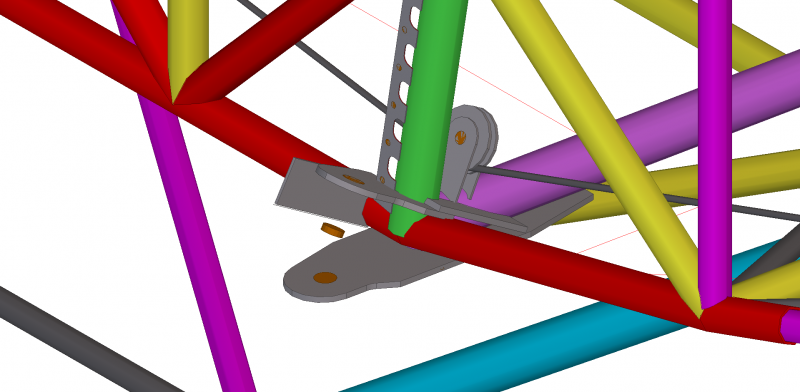
This post should bring the log back up to date ... sometimes it seems to take nearly as long to write the log as is spent building the plane! March 31st to April 3rd 2016 - Still working on control systems, this time it's the rudder and tailwheel. On many taildraggers the tailwheel is either steered by cables (and springs) linked to the rudder control horns and on some other draggers the rudder cables have a splice forward of the rudder connection which allows attachment of a supplementary cable going to the control horns on the tailwheel. Since my tailwheel horns are almost directly below the rudder horns the former method wouldn't be satisfactory, and particularly because as the tailwheel suspension moves, the distance between the rudder and tailwheel horns changes quite substantially. As far as I know the Just Aircraft SuperSTOL elected to get around this problem by having a free-castoring tailwheel and using differential mainwheel braking for steering control, and perhaps their tailwheel can also be locked straight ahead, but I don't like that arrangement, I prefer to have full-time steering control. If I was to add simple splices to the rudder cables for the tailwheel steering, the tension required on the cables going to the tailwheel would pull the rudder cables out of alignment and they wouldn't provide a positive 'feel' or positive control, let alone that they would rub against parts of the airframe at any time that there wasn't a firm pressure on both rudder pedals. My solution is to provide a pair of idlers at the splice point, easier described by images than words. The first picture shows the annoyingly small parts that had to be welded together (back to the spray-paint templating method again) and the last picture shows the assembly installed in the aft fuselage (lower centre of pic) - Having done that I made and added the rudder control horns - with plated re-inforcement on their aft faces so that hopefully no matter hard someone stamps on the pedals it shouldn't deform the rudder horns, and I added the fixed rudder control stops ahead of the rudder horns, welded onto the rudder post. I didn't see any need to make them adjustable, they just allow the rudder to move 27 degrees each way and then reach a dead stop - Continuing the same theme I added the turn limit stops to the tailwheel assembly and also its steering control horns - The next step will be to add the pulleys which guide the rudder cables from the pedals to the idlers, I'll need more than I originally anticipated, to keep the cables clear of the reflex curve in the underside of the aft fuselage. Another 31hrs in that lot, bringing the total time so far to 991hrs.
-
DooMaw - building a STOL
Head in the clouds replied to Head in the clouds's topic in Aircraft Building and Design Discussion
Hi pylon, Yes, I agree with everything you've said. Much appreciate the watchful eye again, thanks! I didn't have any option about using the pushrod in 'push' mode for up elevator, that is a function of the underslung joystick hinge-point, and I wanted that because it keeps the rotation point of the torque-tube where it's needed because I wanted to keep the stick's motion above the height of the knees and avoid the stick pushing peoples' legs around at the extremes of stick travel. To have the joystick hinge-point above the torque-tube would either make the mechanical advantage/lever length of the stick too short, or alternatively position the torque-tube too low ... everything's a compromise. I calculated the buckling strength of the main pushrod and it exceeds requirement, at 6G, by a factor of just under four without any further support - the aerodynamic balancers keep the stick/system loads fairly low. Interestingly, increasing the wall thickness of the pushrod tube doesn't increase its buckling strength significantly since the midspan loading is increased when G is factored in, as you pointed out. Consequently I settled on the 1.25"x0.035" 6061T6 tube which is very light but quite substantial in diameter - in any case as large as I can accommodate between the fuselage diagonals. As far as I can see it looks to be the same as they use on the Foxbat, so I was glad to note that that gave some credence to my material selection. However, what you can't see at this stage is that I did also decide on a 'belt-and-braces' approach and the tube will soon have a mid-span support to prevent flexing under both positive and negative G. It will be a strip of double necked banjo-shaped plywood which will straddle the pushrod at its noble point where, as you pointed out, the tube will not display any vertical motion while moving back and forth. That support will not quite touch the pushrod except under extreme G loading or in the event of any buckling initiating, so it will not wear the tube in normal use. I'll probably apply some mylar adhesive tape where it might touch on those rare occasions. The non-touching support should act like a jury strut does for the wing struts, but which only acts when its needed, and does nothing at other times. Thanks again for your vigilance! -
DooMaw - building a STOL
Head in the clouds replied to Head in the clouds's topic in Aircraft Building and Design Discussion
Yes, definitely. At the start of any design you tend to think you've got the majority of the design details sorted out in your head and just need to get them on paper, so to speak, but in reality along the way there can be so many changes as an earlier detail affects a later one, that if you're not careful the original concept can end up almost unrecognisable in the final outcome. Consequently staying focused on what you want to end up with is pretty important or the design is likely to morph into something different altogether. The best thing I ever did in terms of the above was to learn 3D CAD modelling. During the process of developing the model you build every part of the structure, several times sometimes, so a long time before you actually cut metal you know exactly what you will end up with, and have the opportunity to change it as often as you need to, to make it suit the purpose and/or simplify the construction. .............................. March 28th to 30th 2016 - The next job was to get the elevator controls connected. This involved making three pushrods and connecting them from the joystick to the elevator horn via a walking beam* and a bellcrank*. I made and installed the bellcrank quite some while ago and deliberately hadn't made the walking beam yet because I intended to use it to make the final 'refinement' of the gearing of the joystick-to-elevator horn angular motion ratios. Probably resulting from my time in gliders and helicopters I like quite sensitive controls, so on DooMaw the joystick moves through an arc of 15 degrees forward and backwards with a stop-to-stop linear distance at the control handle of about 240mm - 300mm is probably more like the 'norm' on joystick controlled aircraft of this genre. The elevator control horn moves through 25 degrees each way with a linear motion of around 120mm so via the bellcrank and walking beam I needed to convert 240mm motion into 120mm. The bellcrank was already made and imparts a ratio of 9:10, I had to do that to allow the large elevator pushrod that runs through the aft fuselage to clear the fuselage diagonal bracing. That was achieved by having a slightly shorter bottom arm on the bellcrank which lifted that end of the pushrod slightly. *Someone asked me what the difference is - as far as I understand it a bellcrank has the pivot between the pushrod/cable connections, and a walking beam has both the pushrod/cable connections to one side of the pivot. Along the route of the elevator pushrods there is also a fair bit of angular change i.e. the pushrods don't all point in the same direction. From the joystick the first pushrod runs through the inside of the aileron torque-tube, which points downhill, before attaching to the walking beam. Then the large pushrod goes uphill from the walking beam to the lower attachment on the bellcrank. The third pushrod is nearer to level, connecting the top attachment of the bellcrank to the elevator horn. All these direction changes mean that Ackerman Principle has to be taken into account or we won't get consistent elevator movement throughout the range of motion of the joystick. The reason for all these 'ups and downs' of the pushrods is that it moves the pushrods away from areas you want to keep clear i.e. they go under your elbows in the cabin instead of interfering, then under the baggage area, then the bellcrank changes the motion from push to pull, so that the elevators go up when you pull the stick back, otherwise they would operate in the wrong sense. The final pushrod is positioned where it is simply to get through the HS centre-section frame which allows the HS to fold up for compact hangarage or trailering. There will be a quick-to-remove fairing at that aft HS/VS intersection to allow easy inspection and servicing of all the moving bits down the back there. First I made up the short pushrod connected to the elevator horn, I could take its length direct from the CAD model. Next the pushrod at the other end, which connects to the joystick, and I made the first half of the walking beam. The pushrod that connects to the joystick has an unusual feature in that it must not only move back and forth but must also twist to allow the motion for the operation of the ailerons. One end of the pushrod is connected to the joystick which rotates to move the ailerons, and the other end of that pushrod is connected to the walking beam which doesn't twist. Consequently if you want to use this control method some provision must be made to allow one end of the rod to be rotated by about 50 degrees while the other end doesn't rotate, and this must be done without turning the thread on the 1/4" Aurora ball-type rod-ends. I achieve this by putting very small diameter 'washers' (2mm long, cut from 5/16"/8mm tubing, one washer on the bolt each side of the rod-end). These washers allow the ball to rotate within the rod-end to about 15 degrees each way, so the combination of the rod-ends at both ends allows the pushrod to rotate up to 60 degrees without binding up. It's important to make sure both rod-ends are aligned with each other when the locknuts and locktite are added in the final assembly. I'd forgotten to allow sufficient space for those tiny washers between the rod-end cleats when I made up the joystick some while ago, so I had to carefully cut them off, remake and re-jig them when I found I couldn't twist the pushrod as intended ... I turned up the end fittings on the lathe for the large pushrod, and riveted one end in, and connected it to the bellcrank. Then it was a case of clamping the second large pushrod end - which was not yet connected to the pushrod - to the walking beam and also clamped to the side of the, as yet, overlength pushrod, and adjusting its position slightly up and down the walking beam until the motion of the joystick allowed the elevator horn to just touch its stops at the same time as the joystick also just touched its stops. Moving the connection up the walking beam would make the elevator stops touch first and moving it down would make the joystick stops touch first. Once I had found the spot where they both touched together I could finish the fabrication of the walking beam and cut the large pushrod to length and attach the second end to it. All of that adjustment to determine the walking beam second attachment point could have been done from the CAD model but with all the Ackerman Effect calculations that would be required - and my software doesn't do them for me - it was easier and quicker to do that part by 'trial and error'. Some pictures - That took another 23hrs, for a total of 960hrs so far.
-
DooMaw - building a STOL
Head in the clouds replied to Head in the clouds's topic in Aircraft Building and Design Discussion
Yes, I had designed around control stops on all the flying surfaces but then I was having a chat with Bill Whitney and the subject came up. He said that control surface stops were required when the control was operated by a cable but if it/they was operated by pushrods then control stops at the control lever were sufficient since it was considered to be a 'rigid' system. Naturally that means that cable operated rudders must have stops at the pedals and also at the rudder itself but I guess my elevators probably wouldn't actually require the positive stops at the control surface even though I have designed and installed them in anyway. Thinking back to my C172, I don't recall any stops at the control surfaces and they were cable operated, but the stops were probably at the outboard bellcranks, because from the bellcrank to the control surface was a pushrod. And yes - the load that the rudder system might have to deal with could be very high. I recall when two of us in a Drifter were involved in a close call with a GA plane that came 'visiting' our strip with no prior request or notification and assumed anyone around would be on VHF - which we weren't. The first announcement of his arrival was a beat-up of the strip at 180kts when we were on short final. We saw each other at the last second approaching head-on, he pulled up hard and we flew straight into his wash which threw us nose near vertical at 50ft or so. We missed the ground, just, but afterwards found the rudder cables stretched - the eyelets had elongated considerably - both rudder horns were bent and the attachment of the cables to the rudder pedals was 'strained'. We both recalled how hard we had braced against the pedals. The Drifter pedal system was tested to the required loading during certification - mine was no.2 after certification - so I'd say the requirements are marginal, even at 200lb/pedal. Consequently DooMaw's rudder system is as strong as I can reasonably make it, with most particular attention to the rudder control horns. I must have another read of FAR23 for a refresher ... -
DooMaw - building a STOL
Head in the clouds replied to Head in the clouds's topic in Aircraft Building and Design Discussion
Another happy day yesterday. It was time to fit the horizontal stabiliser. It's a very critical part of the assembly since it all has to be tentatively balanced, clamped and shimmed into position and then measured for accuracy. Naturally it's almost impossible to hang a tape-measure on it when it's so delicately held in place, the weight and pull of the tape would just pull it all out of place again every time you tried. Gladly, due to my day job, I'm well equipped with laser measuring equipment so I was able to get it all set up and use a laser distance measurer from various points each side and near the front of the fuselage. They're wonderfully accurate (mine's calibrated at <1mm at 150m) and since they're non-contact you can easily measure something that's 'just balancing there', or something you can't reach with the end of a tape-measure. After a couple of adjustments I had it in position and was able to tack the first support bracket, adjust it again to correct the pull from the weld, and tack the other side. As with all the welding on this project, about 95% of the time is spent achieving the setup and then the weld just takes moments, it's almost an anti-climax when the job actually gets done. For this job I used a spare 3m length of 7/8" tubing clamped into the support bracket for the setup and once the bracket was tacked in place then I substituted the real centre section of the HS. Once I had the centre section in place on the rear bracket then I could position the front saddle clamps, mark and drill the plate below for mounting bolts. Those saddle clamps sit on packers which provide a primary trim adjustment which will be set during flight trials by substituting thicker or thinner packers. I've started with 8mm and can remove them altogether or add up to another 20mm or so. Changing those packers moves the front of the fixed HS up or down and once set is then left as is - ground adjustable trim, if you like - inflight trim will be provided with a conventional trim-tab on the trailing edge of the port elevator. The pictures below tell the rest of the story. I didn't get to do the 'photo-shoot' on the lawn with the real gear legs and big wheels, as you can see from the last picture it was rather gloomy and intermittent rain all day yesterday. I've also added a pic of the welded joystick that I mentioned but forgot to photograph some while ago. Today's project is to try and get the elevator controls connected. That involves making the pushrods and their end fittings which carry the rod-ends, cutting the torque-tube (which the joystick is connected to) to length and making the forward walking beam located under the baggage area. The WB connects the first and second of the elevator pushrods. To do that there's a fair bit of geometry to finalise to get the right amount of elevator travel so that it just touches the control stops at the full extent of the joystick motion. I have control stops at both the joystick and elevator control surface ends, so it may take a bit longer than just today to get it right. Including the afternoon's work the day before yesterday, fitting the tailwheel hinges, the bottom rudder hinge and a temporary strut to hold the tailwheel assembly up until I make its suspension strut, that's another 13hrs for the log, a total of 937hrs so far.
-
DooMaw - building a STOL
Head in the clouds replied to Head in the clouds's topic in Aircraft Building and Design Discussion
Aw ... shucks guys ... Seriously though, I really appreciate the kind words. As others have commented elsewhere, a plane build is quite a long and lonely road so it's pleasing to be able to share the experiences with the forum and good to hear that folks enjoy reading about it. Can anyone say yet that this has encouraged them to consider a build from plans, or a kit perhaps? Or ... shudder ... has it put anyone off? Yesterday afternoon I pulled the fuselage out again, from under the house, and I added the hinges for the tailwheel and the bottom hinge for the rudder. So it's sitting on three wheels now and easier to move around. Today's project is laser-aligning a piece of 7/8" tubing at the aft fuselage so that I can fit the bent and curved saddle brackets that hold the centre section of the HS. If that goes to plan I might do a trial fitting of the new wheels to the gear legs and fit the real gear legs to the fuselage (at present it's riding on temporary short gear legs and small wheels otherwise it won't fit under the house). That might be the cue for a photo-shoot on the lawn if the weather clears up - it was a bit wet overnight. Coming up shortly is making the seat base. It's made from PVC coated polyester, a bit like truck tarpaulin material but lighter weight. It's laced to the cross-bars in the cabin frame and ends up a bit like those old-style spring folding camping chairs. I already have the fabric but I let my industrial sewing machine go some years ago - so does anyone have an industrial or sail-making sewing machine, or know someone who does within 100km or so of Yatala i.e. I'm halfway between Brisbane and the Gold Coast. I'll supply the fabric already cut out and marked up so it should be a straightforward job. -
DooMaw - building a STOL
Head in the clouds replied to Head in the clouds's topic in Aircraft Building and Design Discussion
Done - I made up some new bends and cut the tailwheel tubular clevis up to graft them in. Then added the top and bottom bearing plates that connect the clevis to the suspension frame. The geometry is now as near identical as I can make it, to the properly installed Scott tailwheel shown in the last image in the previous post. It was pleasing to find that the whole tailwheel assembly shown in the first picture below only weighs 2.3kg. Since the wheel is 1.4kg that means all the steelwork with bolts and spacers is only 900g. I also cut and shut the bottom rail of the rudder to remove the notch which isn't needed now. Another 10hrs to do that lot - a total of 924hrs so far ...
-
DooMaw - building a STOL
Head in the clouds replied to Head in the clouds's topic in Aircraft Building and Design Discussion
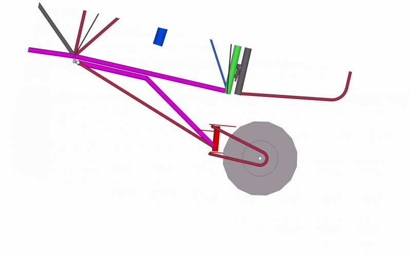
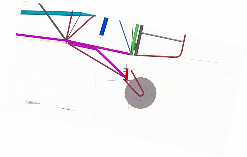
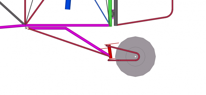
Hi pylon500, thanks for the kind words, and please don't make any apologies, I really appreciate your considered and most valuable input based on your extensive real-world experience, thanks for taking the time. I posted this log online primarily in the hope of inspiring someone into considering their own build, be it a kit assembly or a scratch-build - but the great benefit to me for the DooMaw build is the 'peer-review' aspect. I certainly don't know it all and comments people have made have been invaluable. Yup I agree, I'm no fan of plastic wheels either. However it's a value judgement thing for the interim and not intended to be permanent, but it's the best solution I can come up with at present. That said, maybe forumites could help with keeping their eyes out for a better rim? Early days we did use plastic wheelbarrow-type wheels and even plastic bicycle wheels for main wheels, let alone tailwheels, and we generally got away with it until we had a really hard landing, or one with a lot of drift on. Then the bearings would tear out of the hub. Gladly our flying speeds were so low that other damage or injury was unheard of. That said, I spent a lot of time trying to find the tailwheel components I really wanted and this plastic hub is the best temporary solution. It does have better-designed bearing support than any other I have come across in the past, the molded 'spokes' are quite substantial, the hub annular support for the bearings is quite thick, the plastic is cross-linked polyethylene, so it has a reasonable amount going for it compared to the average. It's a Fallshaw wheelchair wheel with a load rating of 90kg/200lbs, I changed the low-speed roller-bearings for high-speed ball-bearings of course. How the rim choice came about was that I really wanted to run that particular tyre which not only has a rib tread pattern but is also 4 ply and has an excellent load rating of 350lbs with a weight of only 0.8kg. The whole wheel, with tube, bearings and bearing compression spacer is only 1.5kg. The only stronger rim I could find that would carry that tyre was a split steel rim which weighs 3kg on its own. So - given that the early proving flights will be conducted off good surfaces and in moderate winds it gives me time to make a better rim. Unless I can find a suitably light cast or spun aly rim I'll have to machine the dies to have one spun and machine up a suitable hub to suit, and if I'm making one I guess there'll be other bushplane owners (Stollies?) who might be interested too. Damn ... you got me this time! I certainly didn't treat the tailwheel as 'just the little wheel down the back', in fact I gave it a lot of thought, research and design work, but I obviously took my eye off the ball for a moment and completely missed one vital consideration. Sometime last year I entered into a lengthy discussion on HBA about tailwheels but the majority of the subject was about shimmy prevention and avoidance and I have to admit I allowed that to dominate my thoughts and the overall design, and that, in combination with a need to keep the overall height of the tailwheel assembly as low as possible to maintain the 16 degrees angle of attack on the ground, I completely missed that I was designing in far too much trail length/angle. It's not actually quite as bad as it appears in the image I posted earlier, because that image is shown with the fuselage datum level (level flight condition), rather than at the angle it sits on the ground. When the image is rotated by 13 degrees as it would be when at rest on the ground, it brings the steering rake angle positive instead of negative, but I now realise the trail is still far too much. I'm very grateful that you brought this up now, actually one day earlier would have been better, since as you see from the photos attached, I made up the very complex tubular clevis just yesterday ... ;-( Anyway, I've made a quick adjustment to the CAD model to see what can be done as a fix which still uses the same components. I'll have to cut and shut the tubular steel clevis and add a couple more bends but that's the beauty of welded structures, the very fact that you can do that. The new shape retains the positive rake angle but means the wheel must come forward and be more underneath the steering pivot point - this has several effects. Firstly it greatly reduces the steering loads and massively assists in resisting steering into groundloops due to side loads applied by crosswinds - as you mentioned. Secondly it makes the assembly taller which is unfortunate because it creates more drag and also reduces the static AoA but that latter is not as bad as I thought it would be, it's only reduced by 3/4 of a degree - I can live with that, extreme STOL landings would contact the tailwheel first anyway, and its structure and suspension is designed for that. Thirdly, I had shaped the bottom of the rudder to allow the tailwheel to move up into that zone under full suspension motion before contacting the bump-rubber stop, I can get rid of that 'notch' now - another cut-and-shut job. Hi nunans. Yes, covering is in mind at present so peoples' comments and suggestions are most welcome. I've certainly been thinking about Oratex, particularly since it saves dealing with dopes, aluminium coatings for UV protection (which adversely shield the internal part of the VHF antenna I want to use) and, potentially, paint. Though I'm not overly impressed with the colour selections available so would probably choose to paint it anyway. Have you used Oratex nunans? Any experiences to relate? I'm only going to need fabric for the covering of the fuselage and tail aft of the cabin. forward of the cabin will be 0.016" aly sheeting, and I've decided to do the wings with the same, to avoid using twin struts and the extra trouble that would introduce to the wing quick-folding mechanism. ................................. Progress report 17th to 24th March - It's mainly been about completing half-done jobs at the moment. I've been welding on hinges for the tailfeathers and adding the through-tube fittings for the diamond wire bracing. I made up the centre-section of the HS, the complex frame that carries all the hingeing mechanism for the HS as well as the elevator controls. It was critical to get all the hinge alignments right, in three planes, so that the HSs were both 'flat' relative to each other and their rear spars were in a straight line, the individual elevator hinges all had to be in a straight line also, so the elevators would move smoothly up and down without binding and the HS and elevator hinge-lines that allow the whole assemblies to fold up for transport, also have to be concentric so that it folds without binding. The last part of the above complexity was brought about by pylon500's earlier suggestion for the elevator control attachment, and although it was a little awkward to arrange (it required a third jigging to achieve), the benefits are wonderful because there'll never be any risk of forgetting to connect a control after unfolding the wings and tail before a flight. I also made up the brake pedals with their cleats, which go on top of the rudder pedals. Also fitted the new tyres from SDQDI to the Black Max 6" rims I had before, they suit the rims well and the hubs carrying the bearings look quite sufficient. BM do offer a hub that carries bearings for a 3/4" axle as an upgrade to the 5/8" ones that I already have. The brakes though, are another matter. I had been thinking they look rather puny but time will tell. Then I received another extremely kind offer from nickduncs84 who says I can have the rims and brakes he took off his Bearhawk when he fitted the Alaska Bush Wheels. They're Clevelands, and very much more substantial, so many thanks again for such generosity Nick, it's very much appreciated! Some pics - Adding hinges and the through-tubes for the bolts that secure the wire bracing The brake pedals HS flat on the bench with close-ups of the centre section - note the pylon500 hinge, bottom-left in the 4th pic HS in folded position - note the controls are still connected, 3rd pic shows bottom view Tailwheel and the tubular clevis I made up yesterday, 3rd pic shows the 'notch' in the bottom of the rudder to increase tailwheel suspension motion SDQDI's tyres fitted to the Black Max rims - outside, hub side and hub close-up Tailwheel geometry - the first pic is the one posted earlier with the fuselage in flight attitude, the second pic shows how it would have been sitting on the ground, note how this brings the steering pivot angle positive instead of negative i.e. the hinge pin is sloping backward with the top of the pin aft of the bottom, this in combination with the right amount of trail, is necessary to help prevent shimmy. The third pic shows the clevis adjusted to give much less trail and and length - converting what I've already started to make will be today's challenge. This last image shows a bit of what we're trying to achieve for low steering loads and resistance to shimmy. 67 more hours for the log, a total of 914hrs so far.
-
DooMaw - building a STOL
Head in the clouds replied to Head in the clouds's topic in Aircraft Building and Design Discussion
Every now and then we all have a day when everything goes well. And it's said that these things often happen in threes. Well it certainly did for me just recently, and typically they seem to happen just when you've given up hope. Two of my three things aren't relevant to this thread but the third certainly was. I've designed DooMaw to use the Desser 850x6 Aero Classic tyres. They're not quite true Bush Wheels which can probably be described as starting at the 26" Alaskan Bushwheels Airstreak, but they are quite large by LSA standards, and will roll easily over quite rough ground and absorb significant shock. As we all know, anything to do with aeroplane ownership requires a very healthy personal fortune, a friendly bank manager and/or some pretty creditable abilities at finding the best value deals, and the Aero Classics, at US$225 per tyre represent good value. They're a fair step more than the 14" and 15" tyres most LSAs use, for comparison those are around US$60, but they're a lot less than the first of the 'Bushwheels' at well over US$1000 each. So - now it's getting to time to test the gear strut loads and make up the suspension, for the last six months or so I have been trying to get a pair of 850 tyres and tubes over from the US at a reasonable cost. It pretty much looked like the freight was going to double the already significant cost, when taking into account an extra US$80 per tube and the poor exchange rate. In fact, if I bought two pairs of tyres and tubes and could depart at short notice, it was cheaper to buy a discount airfare and go over and bring them back as accompanied baggage, how crazy is that ...? Anyway, I heard that forum member Nick Duncs changed his Bearhawk off 850x6 tyres to the 26" Airstreaks and passed on his 850s to Doug Evans and I found another member who had made a similar 'upgrade'. I sent him a PM and asked if I might buy his 850s to help me avoid this freight problem and I'm still overwhelmed by his response - he said I could have them for the price of a cup of coffee and a chat and a look over DooMaw when he's coming past this way! Well, I've wanted to chat with him anyway, because I've always enjoyed his well considered and interesting posts on the forum, so Thank You again SDQDI, I'm so very grateful - words just aren't enough! Pic below of my fabulous gift - they arrived yesterday by TNT, they look brand new, they don't show any wear on them at all - and they perfectly match the tailwheel I sourced last month. They're certainly a very nice big wheel compared to the 'normal' LSA tyres I already had and which I'd almost resigned myself to having to use for now. The second pic shows the 22" 850x6s, the 'normal' 15"x6 LSA tyres, and the tailwheel for DooMaw with the red hub. Note that the 11" tailwheel is as large as the main wheels were on the very early Drifters -
-
DooMaw - building a STOL
Head in the clouds replied to Head in the clouds's topic in Aircraft Building and Design Discussion
Thanks again Oscar. Yes it's an old chuck that's done a lot of work, that's for sure. But not quite the sentimental old faithful that it might appear. One of my big regrets is that when I went away commercial flying I got rid of my good machinery with the thought that I'd I buy similar again when and if I returned years later. Unfortunately after those years passed it was very much more difficult to find quality machinery than it was in the 1970s and 80s. I did have a nice Swiss milling machine until about 5-6 years ago and a good Taiwanese lathe in the British pattern, but also let them go because they were just a bit too large for current needs, and again I thought I might be able to find something to my taste but a fair bit smaller. No such luck so far, at least not within my rather limited budget. So - a few years ago I needed a small lathe quick-smart for a specific job and just bought a Chinese one off ebay that was the right size, without any thought for its use afterward. I regret I didn't buy the next size up which has a geared head and Norton box for thread-cutting because I detest fiddling with belts and manual change gears for threading and feeding. Also mine doesn't have a powered cross-slide. But worst of all it's an American pattern. In general the American machinery design isn't too bad, after the German and Russian designs in my opinion, with British probably fourth or fifth. However the yanks really did take their eye off the ball with their lathe pattern. Whatever possessed them to control the carriage travel with the left hand, with the consequence of feeding all the hot swarf over that hand, is beyond me. Anyway, the cheapie lathe I bought didn't come with an independent four-jaw chuck so I found one on ebay with a spindle thread that almost matches ... and converted it. It is an unusual construction though it's not so much a removeable faceplate - it just looks like that in the photos because of the 100mph tape I put over the three jaw adjusters I didn't want to move accidentally. But the construction is bolted from the front rather than the usual rear. The chuck originally came from a Hercus or Southbend I think, or possibly a Myford 7. Sounds like your S&B will be a delight when you get it running, I'm jealous ... yes, can't beat collets, particularly for fast repetitive work. Surprised to hear the Taiwanese lathe was inaccurate, I've found them to be quite well made generally, especially considering the price. Mainland Chinese ones are best considered to be a starting point, a kit if you like, from which to start building yourself a lathe by re-machining and adjusting everything except the bed, hopefully ... can't get anything cheaper though, so at least they allow more people to have an entry into machining if they wish. -
Yes, I had a similar 'event' a while ago that really shook me. A half-brick sized rock fell off a truck that was about 50m ahead of me on a freeway, it bounced low several times then made a high bounce. I watched it arcing upwards and found myself steering towards its trajectory. I must have been quite transfixed because I nearly guided it straight through the windscreen into my face. At the last moment I swerved violently aside and it went very close past my side window. The chilling aspect came to me a second later when I realised I'd swerved without thinking and I suppose I might just as likely have swerved to the right in which case it might have hit my passenger instead ...
-
Yes, very sad, RIP. I once wondered how crashes like this might occur - wide open space, the only obstacle in sight. I saw a photo taken in the 1930s, it was taken from about 500ft with a fish-eye lens. It was in one of the Arizona deserts and there was nothing from horizon to horizon except a single tree. Entangled in the tree was a biplane. Apparently the story was that before modern navaids pilots transiting the desert were told to fly East to the tree and then turn left thirty degrees or whatever ... the story goes that over time three planes hit that tree due to object fixation. I saw the object fixation phenomenon at work at a fly-in. It was in the 1980s and there was a hot-air balloon giving mini demonstrations by flying to 100ft or so tethered by a rope. The tether was located too close to the duty runway and although there was no risk of collision it did feel that the balloon was pretty close to the wingtip as you took off. Not only that, but watching each aircraft as they departed, without exception they flew towards the balloon rather than away from it, it seems that if you look towards something you'll fly towards it. I wonder whether O-F had anything to do with this pylon event?
-
Sincere condolences to family and friends. Regarding the objections to discussion of the circumstances, speculation or otherwise, as far as I'm concerned it's another example of political correctness gone mad. It's perfectly natural for humans to be inquisitive and curious, and if we weren't we wouldn't have developed to the extent where we have produced machines that can do all manner of things, including flying. Should there be such a thing as the afterlife I really can't imagine anyone having any objection to a bit of conjecture over how they got there. We all know we have insufficient hands-on crash investigation in most cases, and without peer-discussion of likely scenarios our safety record would never improve. It's not just a case of discussing the actual issue that caused the crash, it's also a case of people giving thought to all the other possibilities that could affect each of us at any time in the future, if they're not regularly brought to mind. We can never have enough reminders because the sky isn't a place that's very forgiving of even the slightest errors. In the unhappy event that something should go wrong with one of my flights, and if I end up on a similar thread, I certainly hope and invite that the discussion about it would be lively and wide-ranging and that it might lead to someone else avoiding the same fate. I'm sure my friends and family would see it the same way.
- 106 replies
-
- 23
-

-

-

-
Small GA Airfield in Brisbane
Head in the clouds replied to RyanBeckley's topic in AUS/NZ General Discussion
Very nice Ryan! Reminds me of a Super Cub I spent many happy times in, mustering cattle on a Kimberley cattle station. You won't have any problems finding someone to unpack and assemble it. The paperwork should be straight-forward too, if a little tedious no doubt. I wouldn't let the locality of an airfield or LAME (licenced aircraft maintenance engineer) affect your choice of where to live or where to hangar too much, as they can be found wherever you go, and they can travel if necessary ... Just make sure you have all the registration and maintenance paperwork for your plane, dating back as far as possible, and the sooner you start the registration process over here the better. I'd start to make contact now to get the wheels in motion. I'm sure there'll be quite a number of people on this forum who have imported and registered planes here but you won't get them with the title of this thread, so I would suggest starting another thread called "Information needed please - for importing and registering a Cub in Australia". -
DooMaw - building a STOL
Head in the clouds replied to Head in the clouds's topic in Aircraft Building and Design Discussion
7th to 16th March 2016 Just a quick catch-up on the log - This session its mainly been about getting the HS, VS, rudder and elevators built. There's not much new 'technology' to write up, just the usual printed plans off the CAD model, wooden blocks screwed to the bench to hold all the parts in place, careful tack welding each side in several places to prevent it all pulling out of shape when completing the weld runs. Bending the trailing edge tubing (CRMO 3/8"x0.035") required care to make sure it was all bent where the corners were supposed to be rather than a bit long or short, and more particularly so that all the bends were in the same plane i.e. so that it would sit flat on the bench rather than with a twist in it. It all came out well and next I have to add the hinges and the through-tubes that accommodate the bolts for the diamond-brace wire rigging. In the photos below you can also see the endcaps on the HS parts with their cleats which allow the HS to fold up for trailering, fitting them required another small jig to keep them aligned so they hinge up without binding. Last I got back onto making the parts for the hinges. Previously I'd used a grinder and then a flap disk to dress a couple of lengths of 8mm x 10mm key-steel to round off two of the edges, and then cut them up into short lengths ready for drilling. I had a couple of people ask me how I would drill them accurately and consistently off-centre, they expected I'd use the drill press and so I received blank looks when I said I'd use the lathe. That made me realise that not everyone has used lathes and four-jaw chucks, of course. For those that may be interested - lathes don't always have to be equipped with a self-centring three-jaw chuck, you can also fit a face plate which allows you to bolt flat plates (or other things) to the spindle and machine them, or a four-jaw chuck which has jaws that are independent of each other and so can be adjusted to hold things of various shapes and hold them off-centre if you desire. To drill something like my small hinge parts I first set all the jaws to hold a piece of 8mm ground bar-stock central, by adjusting each jaw in turn while measuring the run-out of the bar with a dial-gauge. Once I had that running true within a thou or so I could then back one jaw the required amount off-centre to insert the small hinge blocks. I then taped up the other jaw key-holes, to prevent me loosening the wrong one by mistake as I drill the 40 or so pieces. Because these hinge parts act as bearings we want them just the right clearance on the hinge pins so they are loose enough to rotate freely but not so loose they rattle and cause excess wear. It's a fairly fine line, about 0.0015" is ideal. The hinge pins will be 3/16" AN bolts and they're fairly close tolerance on 3/16" (0.1875") so the next drill size above is a Number drill, #12, which is 0.189". To accurately achieve this size and not get an out-of-round hole we need to drill it with a few steps to the process. One of the pictures below shows the drills I used, first a centre-drill to make sure the hole is at the centre of rotation, then a 3/32" pilot drill, then 3/16" and then the #12 drill. Although the #12 drill removes barely any material it's a good idea to run it through quite slowly so as to produce a nice internal finish to the surface of the hole, that and regular lubrication will prolong the life of the hinge considerably. Another 34hrs for the log - 847hrs so far.
-
Small GA Airfield in Brisbane
Head in the clouds replied to RyanBeckley's topic in AUS/NZ General Discussion
Welcome to the forum Ryan, and soon to sunny Queensland! Do you know which side of Brisbane you're headed for? If you're not decided on that yet, then the airfield you select ought to affect your choice of where you also choose for your home because whichever way you go, crossing the river too frequently can be a PITA and the toll costs on the Gateway bridge can add up. They're matters you also want to take into consideration as far as the location of your work is concerned. Also, when you say 'Brisbane', how general is that? Do you mean within Brisbane City itself or within 100km or so of it? Or SE Qld in general? The point being that as you go further out of Brisbane the airfield and maintenance options increase, and many of us would say the flying gets better too. Enough of that - let's see a picture of your Cub please!


.JPG.f6b2d10ec36f36c2083739bc1110eac0.JPG)
.JPG.3000bad8cec898bfa15802755c3d8bd9.JPG)
.JPG.98a47f65f51a228a1fa0a6d069d71aa4.JPG)
.JPG.41c549731a8042f56e132b6aa094f54a.JPG)
.JPG.d9d4c5cd57e47b1feea645c74b509ca9.JPG)
.JPG.59d97b56a0109a64f04eb6bf6bf53411.JPG)
.JPG.826343247cd61fc5b21faa13a5ee990d.JPG)
.JPG.b2a352c066d2d2e6d4014b7891f8eca7.JPG)
.JPG.1b636ceda30f0eca798e8a23a3949a52.JPG)
.JPG.4b432738d1ab52e8c4975d5fa70dd6f8.JPG)
.JPG.acd956665a6b3550628b11b3fb7eba2c.JPG)
.JPG.49e7a2bdc3ef9f20c19763a34f947ba0.JPG)
.JPG.fb5d09370b0934544ea95029a8856fcb.JPG)
.JPG.0434d7ed9bc1dc307af03a054e95e9db.JPG)
.JPG.29cc292aa96c8655f2ba189f02df1ecf.JPG)
.JPG.46b477964a059157adc7f0e58693c6a4.JPG)
.JPG.309749897204ba288d36df1449554e73.JPG)
.JPG.c3387010b39d1f0ccde357d8f5f7be72.JPG)
.JPG.e679bb2147a9ee75c7bc65fc78f27e9f.JPG)
.JPG.e13d0253d751ced0c6d70ca02ad8b0d4.JPG)
.JPG.78d6140562914a35fab941fd4c7dac89.JPG)
.JPG.ffd6148f2e84c2abb1e0560996a129b1.JPG)
.JPG.96a72928954da86fcb113cef757a33d0.JPG)
.JPG.7d63e09b57cca9b4b280e2847b8ad8ed.JPG)
.JPG.83396eb717be787304105384c9829f94.JPG)
.JPG.dbd41d489a08fb9802cb54de919c3756.JPG)
.JPG.0df8207e1a2c749da90f62b4153d6882.JPG)
.JPG.c1ea7efc53b0a81c720c4ae7753474a1.JPG)
.JPG.fd581ad1c9db7e5ed64c9a4e9326d961.JPG)
.JPG.6910200c1ab1f3235a30852442900bff.JPG)
.JPG.b1abb13869b0f768df8225ce0d9fb0cf.JPG)
.JPG.16c248f25255272f98fa9bf175421c0b.JPG)
.JPG.2670436fad9709bee8fb82d9d3c7ad84.JPG)
.JPG.7182a7739ea6eb818f29bff75e585e45.JPG)
.JPG.d49d9cc62eb8d7b31aaf1449fd05ac67.JPG)
.JPG.bf5332464095bf9cdfeb24c323332ab9.JPG)
.JPG.e833286148772327a48df5f8a93778e8.JPG)
.JPG.a21eb12e9b5d349c738c89ff6618500a.JPG)
.JPG.0255a4aa6bc0ef3a416b9415732c889a.JPG)
.JPG.4c1d1059e96d633ca72619f92d090f6b.JPG)
.JPG.31619961b212795a6850aa5807d7f499.JPG)
.JPG.d214b2f9538e500e7823aefd2879985d.JPG)
.JPG.de898a5de795fec959196b273a18802b.JPG)
.JPG.b7259670888a85bf1577c88ebc01006d.JPG)
.JPG.c85c0a57be02c524f9ba99773ff42869.JPG)
.JPG.d2ba8a2b718cb5f56af59b6cf6a38298.JPG)
.JPG.6be8e56d42b9cd130f01ba267e20a1e3.JPG)
.JPG.6cd7aecafb9a6927543283bcfc2dcc77.JPG)
.JPG.c12d1a7fe178055eb8d3014f5ccfeee8.JPG)
.JPG.6f47ccefecee292f0a4a2687886555d0.JPG)
.JPG.de22b8426d84124c5a300b49efb5b11f.JPG)
.JPG.5bae2eca472e802d011b9fe19a041322.JPG)