Tasmag
-
Posts
135 -
Joined
-
Last visited
Content Type
Profiles
Forums
Gallery
Downloads
Blogs
Events
Store
Aircraft
Resources
Tutorials
Articles
Classifieds
Movies
Books
Community Map
Quizzes
Everything posted by Tasmag
-
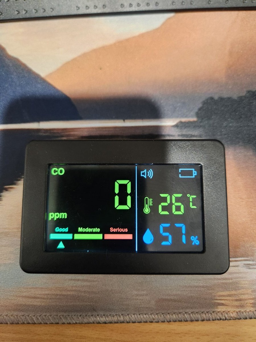
Is there a way to tell the type of sensor, given that it has a 3 minute warm up i suspect an older type.
-
Thanks Skippy, I like the combination of co and humidity on the one i purchased. I have plenty of temp sensors, but no humidity. I like to know the humidity for the carb icing predictions. Mike
-
Freizepilot I like that, wish i had seen it sooner actually. Mike
-
Yep, thats pretty much what I had. Never been one to stop at simple though!
-
Thinking in what you said earlier about a circuit to initiate the start, what about this as the 5 second pulse to turn on. Remove the battery and it will turn off itself. I could leave the battery in but it makes a racket when it goes flat. Mike AU$4.54 | DC 5V 12V 24V Dual Adjustable Cycle Timer Dual Delay On/Off Switch 0-100 Seconds 0-15 Minutes Timer Control Delay Relay Module https://a.aliexpress.com/_mMbe22a
-
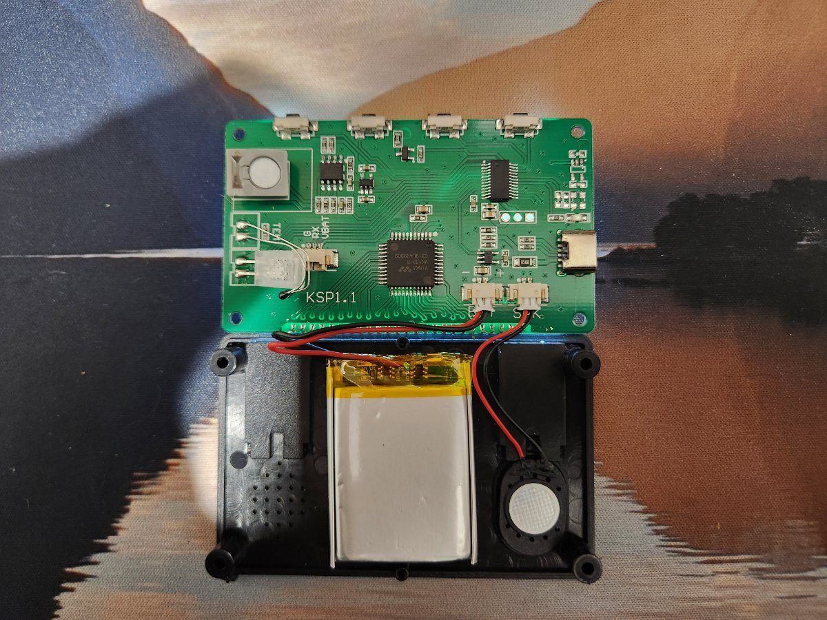
I have found the multimeter. (As soon as I gave up looking for it!) The switches all switch to ground, but interestingly the red and black wires from the battery to the board are around the wrong way. And it does not turn on if you hold the switch and apply power. Mike
-
RFguy Thanks for the replies. For the life of me, I cant find my multimeter to check the switch grounding. I will get back to you as soon as I find it. Based on the Circuit board I would say it is switching to ground though. Mike
-
Long press on the top to turn on or off, short press turns off the screen but keeps the detector running. Right-hand switch in the internal pic as you look at it. The other 3 change °C/F, Voice alarm on/off and Chinese/English voice Mike
-
It seems like the only calibration is a 3 minute warm-up time, as best I can work out anyway.
-
Hi there I am hoping someone with better electronic knowledge than me can assist with a modification I would like to make to a CO detector I purchased recently. I have been using a standard Caravan unit adapted to take aircraft power instead of batteries, but I want to change to a smaller unit I have. The problem is that it does not turn on when power is applied to the charging input. (it was a shot in the dark hoping it would) I don't need the battery, would be happy if it turned on when power is applied and off when not. (Possibly even better that way as the sensor might last longer) Any ideas on a simple way to achieve this.

-
New Trig Radio, weird issues
Tasmag replied to shajen's topic in Instruments, Radios and Electronics
Here are the instructions for the new regulator if that helps Regulator 35A installation PI4A026N Issue 2.pdf -
New Trig Radio, weird issues
Tasmag replied to shajen's topic in Instruments, Radios and Electronics
It just depends on which regulator you have, the old ones go the the main bus, the new ones go direct to battery. Mike -
New Trig Radio, weird issues
Tasmag replied to shajen's topic in Instruments, Radios and Electronics
The easiest way to achieve this is to use a single core shielded wire, connect the shield to ground at the engine and the wire to the mag. Then switch these two to ground the mag. When engine is running the shield is grounded. -
Thanks Glen Yes, that is the servo in use. I'll get some Ferrites and give that a try. Appreciate the thorough reply, especially considering the number of replies you give across the forum for such matters! regards Mike
-
Thanks Glen The system is MGL and utilises CaBus for the control of the Servo. Unfortunately, there are a number of other CanBus terminations within the ground plane area as well, so the shielding lengths you mention are problematic. That was the main reason I was wondering if a metal shield would contain the lobing/Near Field of the signal and minimise the effect on the CanBus. (Probably not even remotely the correct terminology!) Would a solid ground plane be an option to minimise the effect of the Near Field RF. Mike
-
i all I have a jabiru with 2 axis A/P that works a treat, until I broadcast on my second comm. The antenna for this comm utilises crossed copper tape on the floor of the fuselage which continues around the Pitch Servo. The servo is effectively inside the ground plane, but not electrically connected to it. When I transmit on this antenna for longer than a couple of seconds the pitch servo occasionally fails and requires a reboot of the A/P. (Seems to happen most when on 123.45) Would the addition of an aluminium sheet or aluminium flyscreen over the copper tape shield the servo from the RF that is causing the failure? And would that sheet need to be electrically isolated from the copper tape? Thanks in advance Mike
-
Might be worth checking, I swapped the gauge out and was getting really good leak Down numbers, but when tested against another, and checked the orifice, it was always going to give 80/78's😀
-
I purchased this exact kit, total POS. (Not from there, and not that price though) The orifice size looks like it was blown out with Oxy! Been meaning to fix it but haven't bothered yet. (Using a loaner instead) Mike
-
No, only in unfortunately.
-
Sratux is a good option for the MGL iEfis, talks to it via RS232 and gives audio warnings based on height and distance you set. Total cost of about $120. (possibly a little more post COVID, I haven't checked recently) Mike
-
Thanks Nev, looked at this option a while ago but wasn't happy with the ratings compared to the likely surge current when jump starting from a Lithium jump pack. Just a quick edit - I hadn't considered using a starter that is only energised at time of use (by the start pack), was looking at continuous duty, your suggestion will work fine. Ill be giving it a go. Mike
-
What relay do you use to supply the jump start connector that will survive the starting current required for jump starting a dead battery?
-
Great idea, been wanting this for ages when outside vnc areas.
-
Try these, of the Jabiru website. https://jabiru.net.au/wp-content/uploads/2022/08/JPM3L01-5.pdf https://jabiru.net.au/wp-content/uploads/2019/08/JPM0001-6.pdf
-
Thanks onetrack, I'll try UK, but it's the Australian end that is the problem as I understand it. Worth a try though. Mike