Sapphire Posted December 17, 2012 Share Posted December 17, 2012 Solomon said: But i'm not sure what value im suppose to use for the MAC. Could the MAC value be the distance from the root chord to the MAC? I thought MAC [mean aerodynamic cord] was a figure given by the manufacturer. Easy to calculate if the wing was rectangle in shape but harder on irregular taper shapes. Link to comment Share on other sites More sharing options...
Head in the clouds Posted December 17, 2012 Share Posted December 17, 2012 I've been wanting to use this formula to calculate CG:CG= MAC/6+(3 x Tail Area x Tail Moment Arm/ 8 x Wing Area) But i'm not sure what value im suppose to use for the MAC. Could the MAC value be the distance from the root chord to the MAC? Also does any one have any other diffrent methods of working out the CG, my technique i've been using so far was to hoist my aircrft from the spar and see which direction the nose was leaning towards and how much it's leaning. I would then be ok with the weight and balance if it's leaning only slightly forwards about (5 degrees). This also worked well with the scaled model i've made of my aircraft. Solomon said: But i'm not sure what value im suppose to use for the MAC. Could the MAC value be the distance from the root chord to the MAC?I thought MAC [mean aerodynamic cord] was a figure given by the manufacturer. Easy to calculate if the wing was rectangle in shape but harder on irregular taper shapes. Hi Solomon, Since we're moving into an area where you might be planning to set parameters for a real aircraft, and perhaps fly it, let me begin with a disclaimer - I am not an engineer. I have been studying a lot over the years because I design and build planes but I don't have any formal qualifications in this field so you need to check any data derived with someone who can verify it. As a good friend on another forum puts it - I don't even understand half of what I know... All that said, most of the apparently mystical information jealously hoarded by some of the aeronautical engineer types is fairly straightforward and a measured layman's approach will usually produce usable results. In terms of your formula I'm not familiar with it and so I can't either endorse or condemn it. Where did it come from? In any case the value you are looking for is not the distance from the root chord to the MAC, it would be the length of the MAC itself. The formula for determining the MAC varies according to the mainplane planform shape but is nonetheless fairly straightforward, for a rectangular wing it is simply the wing chord length and positioned in the centre of the aircraft, for a tapered and/or swept wing the MAC reduces in length and moves outboard to a position where the area and taper are averaged. Calculations should include the 'theoretical' part of the wing which is occupied by the fuselage, as if the wing was continuous from tip to tip and the fuse didn't exist. A google of Mean Aerodynamic Chord yields several articles with formulae. Be careful though, because the MAC is only relevant to a wing with a symmetrical airfoil and is mostly used because from it the AC (aerodynamic centre) can be determined (at the quarter-chord point of the MAC for a monoplane, or at 23% for a biplane), as the position where the pitching moment doesn't change with change of alpha. However if the airfoil is non-symmetrical i.e. the mean camber line is not straight, then the pitching moment will always change with change of alpha on the basis of - the greater the camber, the greater the change of pitching moment. Nonetheless we mostly deal with what I previously referred to as 'conventional' types i.e. not canards or tail-less designs and the easiest way to determine a reasonable safe starting point is as FH said, weigh the aircraft at three points and use a datum to determine the turning moments then the math is quite straightforward to determine the actual CG and also the changes to the CG position as fuel, pax, avionics, baggage etc are added or removed. For these 'conventional' types a CG between 10% and 25% of the MAC should mean that the aircraft will be positively stable in all flight regimes, actual flight testing will then confirm or disprove that and fine adjustments can be made from data collected. Also, while it is not to be deliberately sought out, slight error in the CG position does not mean catastrophy, if the plane is a little unstable it is still quite flyable since the human is quite capable of correcting small deviations in the flightpath, the problem just gets worse the more unstable the plane becomes. From your formula above you seem to be well aware of the requirements for sufficient tail volume and moment. There are some excellent texts which are useful for budding designers, are you familiar with Daniel Raymer? He has a book for homebuilders but it is quite elementary. I haven't read it and some reviews say it is excellent, others say it doesn't provide enough information to be able to complete a basic design. On the other hand his best known work is called Aircraft Design: A Conceptual Approach and is essential reading for anyone studying aeronautics. It is very well written and easily understood by the layman and covers most of the design aspects of everything from homebuilts to military jet fighters and missiles. I found my (ex library) copy via Amazon, second-hand they sell for between $30 and $60 and are worth every cent. Other authors to look out for are David Thurston (design) and Tony Bingelis (methods for homebuilt aircraft). Hope it helps, Alan 2 Link to comment Share on other sites More sharing options...
motzartmerv Posted December 17, 2012 Share Posted December 17, 2012 Solo. How ya goin mate..;) Thers some good info in this thread, and some not so good... Hit the books mate, a bloke with your brains could have this subject easily gobbled up in no time. Give me a call if you like I will point you in the right direction. If your intention is to apply this knowledge to your homebuilt then you need a better understanding of it than a "pilots level'. Cheers Link to comment Share on other sites More sharing options...
solomon Posted December 18, 2012 Author Share Posted December 18, 2012 There are some excellent texts which are useful for budding designers, are you familiar with Daniel Raymer? He has a book for homebuilders but it is quite elementary. I Thanks Alan! Yes i have both Raymer's Books a member of this website 'sain' has sent it to me a while ago and they are very useful! and I've finished reading the 'Simple Aircraft Design For Homebuilders' and got allot from it, I've also picked up that formula i posted from somewhere in that book. I've also gone through some pages of the 'Concept Approach' and it's quite large book so it might take a while to get through it thoroughly. If your intention is to apply this knowledge to your homebuilt then you need a better understanding of it than a "pilots level'. Hey Andrew! I'm great thanks, and yes I'm trying to build on my knowledge as much as possible so i can apply it to my homebuilt, i know two people around my area building an aircraft and one of them is fully experienced and I'll be sure to get them to come and have a look before i call a proper aircraft inspector. Thanks. 1 Link to comment Share on other sites More sharing options...
Head in the clouds Posted December 19, 2012 Share Posted December 19, 2012 Thanks Alan! Yes i have both Raymer's Books a member of this website 'sain' has sent it to me a while ago and they are very useful! and I've finished reading the 'Simple Aircraft Design For Homebuilders' and got allot from it, I've also picked up that formula i posted from somewhere in that book. I've also gone through some pages of the 'Concept Approach' and it's quite large book so it might take a while to get through it thoroughly. Hey Andrew! I'm great thanks, and yes I'm trying to build on my knowledge as much as possible so i can apply it to my homebuilt, i know two people around my area building an aircraft and one of them is fully experienced and I'll be sure to get them to come and have a look before i call a proper aircraft inspector. Thanks. This is really good to hear Solomon, there aren't enough amateur designers around, and there are some mighty clever folks here in Oz, we just lost the design culture in the 'wilderness years' when we didn't have an experimental category. Look by comparison how much USA advanced while we stagnated... What is the configuration and construction method that interests you? Any pics? Link to comment Share on other sites More sharing options...
facthunter Posted December 19, 2012 Share Posted December 19, 2012 Bill Whitney has put out a lot of stuff which is easy to understand and ( in my opinion) covers all the essential elements of design at the level we are at. A lot of it is structural in a very practical sense, He analyses all the loads thoroughly and simply and he doesn't like wood because of it's variability of quality. The aerodynamics he uses are proven, not radical eg he always uses low aspect ratio tail feathers because they are more effective over a large range of angles of attack He designed the Southern Cross replica and the Whitney Boomerang which is a very adequate strong, Trainer probably too good for the market as most get away with lesser aircraft, cheaper. The useable Cof G range for the wing would be a function of the shape of the aerofoil. and is expressed in relation to MAC Which only gets a bit complicated when the wings are tapered or swept one way or the other. He puts out a disc and accompanying notes .. Not sure if he is still doing it but there may be second hand copies out there...Nev Link to comment Share on other sites More sharing options...
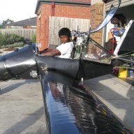
solomon Posted December 19, 2012 Author Share Posted December 19, 2012 Here are some photos of the fuselage structure, it's made from galvanized steal and the skin I'm going to be using is fiberglass. The other picture of a silver plane is just a 1/10 scale of what the finished product would look like, note that I wasn't able to get the desired curves i wanted because of the material i was using in the models fuselage. So the actual one I'm building should be slightly more streamlined i also didn't add the engines and landing gear on the model. So far from the fuselage structure you see weighs 120kg including the engines. Link to comment Share on other sites More sharing options...
Gentreau Posted December 19, 2012 Share Posted December 19, 2012 Hit the books mate, a bloke with your brains could have this subject easily gobbled up in no time. .... Could I add a recommendation to your booklist Solomon, Flying your own wings by Chris Heintz, the designer of the Zenith/Zenair range of aircraft as well as the Robin HR200 GA aircraft. 1 Link to comment Share on other sites More sharing options...
Head in the clouds Posted December 19, 2012 Share Posted December 19, 2012 You're right cfi, but blame me not Solo, the statement was mine. I need to pay more attention to specificity. Yes the CG remains static and the CP might move, as I clarified in my next post. In the example I described here neither of them were moving except relative to each other due to the pitch rotation, and their relativity is in the horizontal (to the ground) plane. And yes, to be fully correct the CP would move forward as well in this example, as long as it was a cambered airfoil, but that doesn't affect the low-wing vs high-wing example being discussed. Thx for bringing it to my attention, Cheers, Al Link to comment Share on other sites More sharing options...
motzartmerv Posted December 19, 2012 Share Posted December 19, 2012 CoG's dont move anywhere...CoP's do.. You sure about that chief? Link to comment Share on other sites More sharing options...
motzartmerv Posted December 19, 2012 Share Posted December 19, 2012 As in when fuel burns off? In a short coupled design Like Solomon's I would be very concerned about the CofG indeed shifting with fuel burn aswel as the pilots weight shifting around. Simply leaning forward could change the cofg by a considerable amount when you consider that say 25% of MAC could well be 10% of the total moment of the aircraft. In a design such as this, the CofG does and will indeed shift.;) 1 Link to comment Share on other sites More sharing options...
Sapphire Posted December 19, 2012 Share Posted December 19, 2012 We going to have to wear a straight jacket in some of these a/c to keep the c of g more constant. Even outside the a/c there could be benefits. Link to comment Share on other sites More sharing options...
facthunter Posted December 19, 2012 Share Posted December 19, 2012 You are better to keep your variables Fuel and load (people) as near to the centre of lift as possible Solomon, Once you bend the load elements of your design its harder to know what strength it has. A lot of good steel tube frames are based on a triangular prism. This gives you rigidity and minumum weight and easy to calculate the material sizes. When it is triangulated, all the elements are essentially in either tension or compression. You treat it as a pin jointed frame. Nev 2 Link to comment Share on other sites More sharing options...
Gentreau Posted December 19, 2012 Share Posted December 19, 2012 We going to have to wear a straight jacket in some of these a/c to keep the c of g more constant. Even outside the a/c there could be benefits. And be sure tie those sheep down well . 2 Link to comment Share on other sites More sharing options...
motzartmerv Posted December 19, 2012 Share Posted December 19, 2012 You would need more than a straight jacket for Solomon. He would work out a way around it in seconds...;)... While he was staying with us, on a boring rainy day, he made a working jet engine from a spray can, a LPG gas bottle, an air compressor and some hoses. It ignited and sustained itself.. Actually..i have a video of it somewhere. 1 Link to comment Share on other sites More sharing options...
solomon Posted December 20, 2012 Author Share Posted December 20, 2012 As in when fuel burns off? In a short coupled design Like Solomon's I would be very concerned about the CofG indeed shifting with fuel burn aswel as the pilots weight shifting around. Simply leaning forward could change the cofg by a considerable amount when you consider that say 25% of MAC could well be 10% of the total moment of the aircraft.In a design such as this, the CofG does and will indeed shift.;) I haven't installed the fuel tank yet, but it's going to be very close to the CG, in fact it's probably just behind, so if fuel burns off it will be just a tad nose heavy. Link to comment Share on other sites More sharing options...
Head in the clouds Posted December 20, 2012 Share Posted December 20, 2012 Thanks for the pics Solomon. I can't really tell from the photos but it looks like you have a few unresolved connections which result in bending moments, as FH mentioned above make sure all your truss members meet at common nodes as if the whole structure could be held together by pins at single points. Otherwise you would be relying on the welds to resolve bending loads. Your empennage truss looks to be a 2D one i.e. not a triangular or rectangular box truss in which case it will not have much strength for side loading by the rudder or twisting, also from rudder inputs or spinning (!) ... so you may need to add drag cables from the half span point to the tail. Got any drawings? 1 Link to comment Share on other sites More sharing options...
facthunter Posted December 20, 2012 Share Posted December 20, 2012 If you are good at reading, get a copy of the EAA books by Tony Bingelis which will cover the normal techniques that have been used for the last 20 years or more. Generally they are simple practical and work. You should be able get a lot of it second hand. The cutting edge of this game is with composites, Which I don't think is appropriate for the amateur and bad for your health if you aren't carefull. Steel tube is still widely used for the main fuselage truss and you can hang ply bulkheads off it and use stringers to get a beautiful shape with fabric over the lot. try to keep your design simple. Nev Link to comment Share on other sites More sharing options...
M61A1 Posted December 20, 2012 Share Posted December 20, 2012 I dont know if this will help in you efforts, it was posted for me on another site, I found it useful. Apparently came from a Boeing design engineer some years ago. 3 Link to comment Share on other sites More sharing options...
Head in the clouds Posted December 20, 2012 Share Posted December 20, 2012 That's not a bad summation M61. One flaw I spotted is the angles, No 8 says not less than 15* from the datum whereas it should be from the mainplane chordline which would have a fixed incidence of approx 3* so No 8 should say 12* but then even that much can be hard to achieve in many configurations, even making 'mounting the beast' very difficult for some designs and No 10 is virtually impossible to achieve in a tractor design so weaving taxiing becomes the order of the day. Equipping the craft with flaps really helps with the No 8 static angle allowing a further reduction of at least 3* without risk of banging the tailwheel on before the mains in a full stall landing. No 5 might be a bit less than conservative but depends on the airfoil, with non-laminar foils I'd stick to max 25% aft CG position until some flight-test data has been collected. Link to comment Share on other sites More sharing options...
solomon Posted December 20, 2012 Author Share Posted December 20, 2012 This is a 1/10 scale drawing of my aircraft i haven't added much measurement in it because i didn't want to make it look too complicated, the other one with three different views in one page is just a rough sketch before i made my scaled drawing. It's not very clear on the photos but the small red dots you see are the CG symbols and the tubing thickness you see are exact scale. And thanks M61A1! that would be quite useful! Sketches: 1/10 scale drawings Link to comment Share on other sites More sharing options...
Phil Perry Posted December 20, 2012 Share Posted December 20, 2012 C of p is used to unstall an a/c. If you stall, the c of p moves back causing the nose to drop. Probably saved a lot of people. Where things turn to disaster is when the stalled wing drops, opposite aileron is applied, stick is pulled back as the ground comes rushing up. I said it before, you just signed your death warrent. Practice correct recovery at 4000ft Yeah, practice recovery at a SAFE ALTITUDE / HEIGHT / FLIGHT LEVEL, or whatever reference you are operating on. I dunno about 4000 feet though, if you did that anywhere Ben Nevis oop in Bonnie Scotalnd, you might encounter a windscreen full of rocks very quickly . . . I know what Sapphire actually meant of course,. . . . which is, give yourself perhaps a few thousand feet ABOVE THE NEAREST NASTY HARD BIT OF GROUND before attempting the practice. Instance : In the UK, in all aerobatic manouevres, the pilot MUST be able to recover to normal flight using a minimum reference of 3,000 feet above mean surface level. This will at least give you a safe margin to recover from a manouevre which went wrong, with time and a sensible vertical displacement above mean ground level to try out a few different recovery techniques. ( If neccessary ) Phil I hate aerobatics now. . . ( the GEE forces make me ill. ) [ Silly old fart ] 1 Link to comment Share on other sites More sharing options...
Sapphire Posted December 21, 2012 Share Posted December 21, 2012 I picked 4000 ft because if you go much higher you end up above 5000ft where flight is more organized. Of course if you are doing aerobatic manoevers over Mt Everest then add a bit more. Link to comment Share on other sites More sharing options...
Phil Perry Posted December 22, 2012 Share Posted December 22, 2012 Ok mate, I see, . . We don't have that distinction in the UK, any altitude is OK, up to 10,000 feet QNH / RPS / FL 100, after which other regulations apply, like the requirement to carry supplemental oxygen breathing gear "FOR YOUR PASSENGER" ( ? ) and there is also a mandatory requirement for a flight plan to operate at or above that vertical displacement. As you are probably aware, I was just getting at the fact that a good bit of clear air is a bit of a good thing to have underneath you when mucking about with aeroplane flight envelopes ( OR experience envelopes more like. . . ) In the UK, another rule is NO MOGAS ( Garage unleaded ) to be used in microlight, or other permit to fly aircraft flying above 5,000 feet. . . . . And then there's the looming problem of the addition by stealth of unknown quantities of ethanol additive which have been causing issues with fuel lines, tanks, filters and other fuel system components on outboard motors, , small power tools ( Chainsaws ? )and other 2 stroke and four stroke engines in the U.S for some time, the U.S. Govt. is considering adding at least 15 percent Ethanol to all petroleum fuel supplied to the automotive garage industry, but some posters on youtube have had samples analysed, and found that in some cases that the ethanol content has exceeded 37 percent !! This does NOT bode well for the rest of the world, because, as we all know, what the USA does, most Western countries almost always follow, especially if the oil companies are going to make a bigger profit margin, which, at the end of the day, is the only reason ( apparently ) for their continued existence. Anyway Sorry again for the thread drift. . . . . . ( Don't know how I got onto that . . . .! ) Only 2 days left. . . . . . . Ho Ho Ho ! Phil 1 Link to comment Share on other sites More sharing options...
Recommended Posts
Create an account or sign in to comment
You need to be a member in order to leave a comment
Create an account
Sign up for a new account in our community. It's easy!
Register a new accountSign in
Already have an account? Sign in here.
Sign In Now