gimballock Posted April 17, 2014 Posted April 17, 2014 So tell me, exactly how big a deal is intersection drag? Would it pay any decent dividends to design a plane where aerofoils/wings/etc join the fuselage at such a gradual rate so as to avoid nearly all intersection drag or is the payoff really not that much compared to the annoyances and overheads involved? Thanks. Gimballock
Old Koreelah Posted April 17, 2014 Posted April 17, 2014 Birds have gentle, organic curves at all intersections. That's the result of an awful lot of development.
gimballock Posted April 17, 2014 Author Posted April 17, 2014 Okay, so why are there so few designs that particularly try to address this? Most aircraft that I've seen have quite flat intersections at the wing root. Even the ultra-slippery teardrop-shaped sailplanes don't do a very good job.
Old Koreelah Posted April 17, 2014 Posted April 17, 2014 I guess the best design features are found in the most efficient aircraft. Especially the ones which don't use brute force to get thru the air. Another overlapping thread has some very slippery sailplanes, and some of those use filleted intersections. http://www.recreationalflying.com/threads/spats.116652/#post-422331
facthunter Posted April 17, 2014 Posted April 17, 2014 A lot of commercial designs have had extensive fillets and fairings since before WW2. The designs would have been subject to wind tunnel testing and proven. Efficiency means more range and less fuel cost equals more payload. Poorly designed ones would be a waste of time and money. Simplicity of construction, speed envelope and cost are considerations. At the speeds we fly, generally, probably not worth doing unless the plane is "moulded" (composite) where it would/could make it stronger as well. Nev 1
Dafydd Llewellyn Posted April 18, 2014 Posted April 18, 2014 Take a good look at the wing root fillets on a Spitfire. It had the highest limiting Mach No. of any WW2 fighter
Bob Llewellyn Posted April 19, 2014 Posted April 19, 2014 So tell me, exactly how big a deal is intersection drag?Would it pay any decent dividends to design a plane where aerofoils/wings/etc join the fuselage at such a gradual rate so as to avoid nearly all intersection drag or is the payoff really not that much compared to the annoyances and overheads involved? Thanks. Gimballock It's a big enough deal that Heinkel made the wings on the He111 perpendicular to the fuselage surface, even at the expense of "gulling" the wings outboard, and faired the roots (See also Corsair...). Airliners put external mitres on their fuselages where the wingroots are (there is a compressibility reason as well, but the interference drag is still valid). Cessna stuck the wings on top of his smaller products, which neatly avoids any problems of interference from the wing supervelocity (higher speed air over the top). Thorp kept the PA-28 fuselage constant width to the wing TE, and added fillets reducing the thickness/chord of the root, thus reducing local supervelocity. Henry Millicer positioned the maximum width of the AirTourer at the wing TE. Vans start tapering their fuselages foward of the wing TE, and do not fit fillets, and did not offer any sort of radiused fairing on the earlier products (that I'm aware of); which gives the interesting characteristic that, if the propellor actually stops rotating in flight, at best L/D speed the separation from the wingroot/fuselage blankets the tailplane sufficiently that, if the CG is fowards - say, with an IO-320 driving a CS metal airscrew - there is insufficient elevator power to flare. (Any RV driver who thinks it's normal to not be able to three-point with the flaps out, or to need a blip of power to flare, has been demonstrating the point). Rutan stuck the fan on the butt end of his earlier designs, effectively vacuuming the interference wingroot area, and in any case the Vari-anythings have ample fillets and generously radiused fairing. The P-51 Mustang used fillets; so did the Bonanza. Aircraft that have gone to the trouble and expense of fillets or fairings include most WW2 fighters, most production low-wing GA aircraft post WW2, and most airliners post WW2 (look at the Super Connie!). Provided you stay at a lift coefficient of less than 0.3~0.4, interference drag from the wing-fuselage junction will be insignificant if the fuselage incidence is appropriate for cruise. For a typical small aeroplane, the increased parasite and induced* drag during the takeoff-climb approaches the weight penalty of an extra passenger. *Not only does the stagnant wake increase in area by 1~2% of the wing area (or 15~30% of total drag) at best L/D, but the irregularity caused in the spanwise lift distribution increases the induced drag measurably) Consider the venerable Piper Cherokee; unspatted and in average paint, it'll get a best L/D of about 1:10 at ~65 knots. At 2,000lb, that equates to 40 (thrust) HP to stay up. Now, add 4.5* square feet of extra stagnant wake from putitative wingroot interference drag - a force of ~63lb if the wake be truly stagnant, but ~40lb is likely nearer the truth. So, an extra 8 DHP, or a 20% increase in the power required for level flight. In climb terms, the cost is 132 fpm. If we assume that the Cherokee at 2,000lb will manage 832 fpm ROC sans interference drag, then the 132 fpm that would be lost, could be recovered by reducing the weight by177lb. *Turbulent transition and interference separation both develop - spread - at ~15 degrees to the airflow; so on a 5' chord, if the inteference turbulence starts at the LE, it'll be about 1.34 ft out along the TE and 1.34' up the fuselage side, and oscillating to give an effective area around the square of this distance. Check wooltufting and smoke-trail wind tunnel pictures, there'll be enough on the web; or I can find you a couple of NACA report numbers. To check the sanity of this, a fixed pitch propellor optimised for ~100kts cruise will do very well to exceed ~70% efficiency at 65kts; and, with an unspatted 6.00 x 6 hanging off the noseleg, propulsive efficiency would be less than 65%. As such a prop would also hold the engine revs back in slow climb, the available THP will be around 150 x 0.9 x 0.65 = 88 THP; less 40 to eliminate sink, leaves 48 THP to climb with, giving 790 fpm ROC at 2,000lb. So, the numbers are in the ballpark, and the fillets on the Cherokee are worth about 12 SHP in climb, or at least one passenger, or a lot of your fuel - or not operting out of a strip where you need the performance! 2
bexrbetter Posted April 19, 2014 Posted April 19, 2014 Vans did work in this area for the RV12, might interest you to read up about it.
Dafydd Llewellyn Posted April 19, 2014 Posted April 19, 2014 Some of the more crude low-wing GA designs omit fillets in order to get sufficient pre-stall buffet from the separated flow affecting the tailplane, in order to (or in an attempt to) avoid the necessity to fit a stall-warning device. Saves the cost of the fillets, too. That thinking, carried right through the design, gets a cheaper product on the showroom floor; the idea is that the customer only sees the initial cost, not the ongoing cost. This goes with the point of view that most people "only buy the paint" - if it has a snazzy paint job, a low aspect ratio, and lacks wing root fillets, you can make a pretty fair guess what the manufacturer's priority was. The costs, as Bob has pointed out, are some reductions in performance all round - higher lift-off and touch-down speeds, reduced climb rate, and increased cruise fuel consumption. The effects are not huge, but you only have to compare a Cessna 172 model that has a 150 HP Lycoming, and a Piper Cherokee 140 with the same engine power, to see the difference these things can make. However, the practicalities of owning and operating an aircraft often outweigh such considerations. Yes, the Cherokee 140 was a bit less lively than a comparable 172; but it had a big nosewheel, so you could land it in a paddock if necessary without too much risk of damage. It also did not blow over as easily when tied down outside. Its fuel tanks didn't hang on to water, and you did not need a ladder to refuel it. Pity that Piper's emphasis on low first cost was carried through to omitting proper corrosion-protection on things like the rear wing attachment, and floating pistons in the undercarriage oleos to keep the oil and the air apart. The reality is that all aircraft design is compromise, and the trick is to make the right choices in the compromises. For example, the British made a deliberate choice to omit de-icing provisions from their bombers. The Heinkel 177 was an attempt at higher aerodynamic efficiency than was the Lancaster. History shows that that was the wrong choice for Heinkel. When you look at an aircraft, try to see what the designer's choices of compromises were, because the way to find what is satisfactory to you, is to find a set of compromises that match you needs. A prime example, with recreational aircraft, is lift struts; the differences between a cantilever wing (no struts), a torsionally-stiff strut-braced wing (one strut per wing) and a torsionally flexible wing (two struts per wing) are profound. How many purchasers have the slightest idea of what these compromises imply for the utility of the aircraft? These things are worth some study, in my view. 1
rgmwa Posted April 19, 2014 Posted April 19, 2014 David Lednicer a CFD analyst with VSAERO did an interesting analysis of an RV-6A in the Sport Aviation Magazine April 1997 issue. "To improve the wing pressure distribution, I first designed a new wingtip. My aim was to straighten out the isobars near the tip of the wing, with constraints that the wing span could not be increased and that all changes to the tip had to occur aft of the faired-in navigation light. After three design iterations, the wingtip isobars were now well-shaped and the calculated induced drag had decreased. Next, I designed a wing root fairing. I felt that a large convex obstruction was needed at the wing root to force the isobars forward. After several iterations, I found such a shape, and the calculated induced drag again diminished. By contrast, a conventional concave fairing was found to have little effect on the wing pressure distribution and to produce no improvement in induced drag. The traditional concave wing root fairings are not always the way to reduce drag!" One RV-6 owner reported that he bought his aircraft with after-market intersection fairings fitted. They looked great, but he found his aircraft was not getting the speeds that Vans performance figures said it should. He finally took the fairings off and gained the missing 8 kts. I guess all that shows is that what looks intuitively right, doesn't always work. rgmwa 1
Bruce Tuncks Posted April 19, 2014 Posted April 19, 2014 I put aftermarket Striefeneder wing-fillets on my Libelle glider and it is better now. It can be thermalled a couple of knots slower as the buffeting of the tailplane is much less. The high-speed performance effect is beyond my ability to measure but I think it is the same or a bit better than before. The unfilleted Libelle was the cheapest, best-looking and best-selling glider in its day, but it never won a world championship, being beaten by the Standard Cirrus which did have fillets. Bruce
Dafydd Llewellyn Posted April 19, 2014 Posted April 19, 2014 David Lednicer a CFD analyst with VSAERO did an interesting analysis of an RV-6A in the Sport Aviation Magazine April 1997 issue.I guess all that shows is that what looks intuitively right, doesn't always work. rgmwa Dead right! However, induced drag and wing root separation are two separate things. 1 1
gimballock Posted April 20, 2014 Author Posted April 20, 2014 I'm picturing an aircraft that might be described as the lovechild of a Glasaflugel H101 Salto sailplane and a Monnett Moni with gradual joins of wing roots and v-tail. Obviously with shorter wings/tail to be more power plane than glider (approximately the rough dimensions of a Corby Starlet/ Taylor Monoplane etc.) Yes, it would obviously have to be of glass/carbon fibre construction. As I've said before, I don't have the means or skills to design/build my own aircraft but I'd be interested in the opinions if you seasoned professionals as to the imagined performance of such an aircraft. Gimballock.
djpacro Posted April 20, 2014 Posted April 20, 2014 The "bible" is Fluid Dynamic Drag by Hoerner and his analysis of the Me109 is a classic example of how to do a drag breakdown. Note that there is an induced drag component of interference drag. When I get to a PC rather than iPad I will include a link to an extract from his book with that Me109 data showing interference drag vs other drag elements.
Dafydd Llewellyn Posted April 20, 2014 Posted April 20, 2014 All fixed-wing aircraft obey essentially the same basic physical principles; their performance is defined fundamentally by their wing loading, wing aspect ratio, equivalent flat-plate drag area, and power loading. Or if you prefer, span loading, flat-plate area and power loading. Without those numbers, it's not possible to predict the performance. So you need to make a better "first guess" than your description, before anybody will be able to come up with any numbers. A good starting point is the required stall speed; with this and the weight, the wing area can be estimated. Most aircraft with a power loading of 10 lbs per horsepower or slightly above, manage to cruise at about 2.5 times the flaps-retracted stall speed. A higher power to weight ratio will allow maybe 3 times the stall speed; this is about the practical achievable range. An extreme WW2 fighter type might get to a TAS of 4 times the sea-level stall speed, at its optimum altitude. Jet airliners get high true airspeeds by flying so high that they are cruising not much above their minimum drag speed. Polishing the thing and getting close to an "ideal" aerodynamic form does not change this speed relationship very much; but it can reduce the fuel consumption. So the "ultimate" sexy shape actually has less effect on performance than is popularly imagined. The drag breakdown analysis allows you to estimate the equivalent flat-plate drag area (the hypothetical area of a flat plate pushed into the air and subjected to the full dynamic pressure, 0.5 x the air density x the speed squared). Hoerner* is indeed the "bible" for this, but how to use the result to estimate performance needs a bit more; a useful guide to both realistic actual drag data and how to put it together to estimate various aspects of performance, is "The Design of The Aeroplane" Author Darrol Stinton, ISBN 0-632-01877-1; it's quite readable, even if you don't follow the mathematics. *you won't find Hoerner in your local library; it was published only by the author, so it's a very rare book. Aviation professionals and university libraries are likely sources. Below the critical Mach number (about M = 0.6), Drag can be represented by two parts, namely the "parasitic" drag, which increases in proportion to the square of the speed; and the "induced" drag, which is basically due to the fact that, because the wing pushes air downwards in order to support the aircraft, it is always flying somewhat "uphill". It decreases in proportion to the fourth power of the speed. At the speed for minimum drag, half the drag is parasitic, and half is "induced" drag. This normally occurs at around 1.2 to 1.4 times the flaps-retracted stall speed. This idealisation is varied a little by the fact that the parasitic drag of the wing can change somewhat erratically, if it experiences a significant amount of laminar flow over portion of its operating range; however the literature on "laminar airfoils" is not too realistic in the real world. All this is also affected by the propeller; firstly by the aerodynamic efficiency of the propeller, and also by the increase in drag of parts of the aircraft immersed in the slipstream. Most simple performance estimates make a fairly crude assumption about the likely propeller efficiency, and are often optimistic because of that. In an aircraft that cruises at less than 100 knots or so, the propeller efficiency can be surprisingly low. Again, Stinton gives some useful rules of thumb.
Bob Llewellyn Posted April 20, 2014 Posted April 20, 2014 All fixed-wing aircraft obey essentially the same basic physical principles; their performance is defined fundamentally by their wing loading, wing aspect ratio, equivalent flat-plate drag area, and power loading. Or if you prefer, span loading, flat-plate area and power loading. Without those numbers, it's not possible to predict the performance. So you need to make a better "first guess" than your description, before anybody will be able to come up with any numbers. A good starting point is the required stall speed; with this and the weight, the wing area can be estimated.Most aircraft with a power loading of 10 lbs per horsepower or slightly above, manage to cruise at about 2.5 times the flaps-retracted stall speed. A higher power to weight ratio will allow maybe 3 times the stall speed; this is about the practical achievable range. An extreme WW2 fighter type might get to a TAS of 4 times the sea-level stall speed, at its optimum altitude. Jet airliners get high true airspeeds by flying so high that they are cruising not much above their minimum drag speed. Polishing the thing and getting close to an "ideal" aerodynamic form does not change this speed relationship very much; but it can reduce the fuel consumption. So the "ultimate" sexy shape actually has less effect on performance than is popularly imagined. The drag breakdown analysis allows you to estimate the equivalent flat-plate drag area (the hypothetical area of a flat plate pushed into the air and subjected to the full dynamic pressure, 0.5 x the air density x the speed squared). Hoerner* is indeed the "bible" for this, but how to use the result to estimate performance needs a bit more; a useful guide to both realistic actual drag data and how to put it together to estimate various aspects of performance, is "The Design of The Aeroplane" Author Darrol Stinton, ISBN 0-632-01877-1; it's quite readable, even if you don't follow the mathematics. *you won't find Hoerner in your local library; it was published only by the author, so it's a very rare book. Aviation professionals and university libraries are likely sources. Below the critical Mach number (about M = 0.6), Drag can be represented by two parts, namely the "parasitic" drag, which increases in proportion to the square of the speed; and the "induced" drag, which is basically due to the fact that, because the wing pushes air downwards in order to support the aircraft, it is always flying somewhat "uphill". It decreases in proportion to the fourth power of the speed. At the speed for minimum drag, half the drag is parasitic, and half is "induced" drag. This normally occurs at around 1.2 to 1.4 times the flaps-retracted stall speed. This idealisation is varied a little by the fact that the parasitic drag of the wing can change somewhat erratically, if it experiences a significant amount of laminar flow over portion of its operating range; however the literature on "laminar airfoils" is not too realistic in the real world. All this is also affected by the propeller; firstly by the aerodynamic efficiency of the propeller, and also by the increase in drag of parts of the aircraft immersed in the slipstream. Most simple performance estimates make a fairly crude assumption about the likely propeller efficiency, and are often optimistic because of that. In an aircraft that cruises at less than 100 knots or so, the propeller efficiency can be surprisingly low. Again, Stinton gives some useful rules of thumb. A useful starting point for design estimations is that, in incompressible flow (ie well subsonic) for a very fair fuselage with elliptical wings: 1) The total drag is least when the parasitic and induced drag are equal (as Dafydd mentioned); 2) The minimum sink speed occurs when the induced drag is 3 times the parasitic drag; 3) The best L/D speed is 1.315 times the minimum sink speed. It's virtually impossible to do better than these, as they are a result of the basic physics. Note that (2) predicts that soaring aeroplanes should have high aspect ratio wings to minimise induced drag, and (3) demands that transport aeroplanes fly at less than twice their stall speed for good efficiency. (3) also means that high speed ratios require huge power. In a small powered aeroplane it'll be virtually impossible to achieve a speed where the induced drag becomes 3 times the parasite drag, as the Reynolds number range makes it a great challenge to avoid premature separated flow from the fuselage.
gimballock Posted April 20, 2014 Author Posted April 20, 2014 Is there any software out there that would allow you to simulate such a thing? I mean, I'm reasonably competent with maths and physics, but at this stage I'm..... well... like a dog in a forest not knowing which tree to pee on! You've given some good advice, but I don't know where to start to apply it all. Maybe an aircraft design package exists to allow me to come up with some on-paper numbers? Thanks, Gimballock. 1
Bob Llewellyn Posted April 20, 2014 Posted April 20, 2014 Is there any software out there that would allow you to simulate such a thing?I mean, I'm reasonably competent with maths and physics, but at this stage I'm..... well... like a dog in a forest not knowing which tree to pee on! You've given some good advice, but I don't know where to start to apply it all. Maybe an aircraft design package exists to allow me to come up with some on-paper numbers? Thanks, Gimballock. Induced Drag is estimated as wing area (S) x 1.2 x Cl (lift coefficient) squared / (PI x A(spect Ratio)) for a constant chord wing (square tips) of AR 5 ~ 8ish; 1.1 x Cl / (PI x A) for a straight tapered wing in the same aspect ratio range; and Cl / (PI x A) for an elliptical wing - but forget that one, unless you like snap rolls as stall warnings... You calculate your Cl at any speed from: Lift = 0.5 x rho (air density) x V squared x (S(wing area) x Cl), rearranging for Cl. Assume your maximum Cl (unflapped) will be ~1.45, and you won't be far wrong at all. Forget the "this airfoil section gets 1.8!" claims, those are not figures for 3-dimensional wings, OR at real Reynolds numbers, OR in typical air. Your fuselage drag coefficient will be in the range ~0.25 (Cherokee style) to ~0.15 (Sonerai), ignoring cooling drag, based upon the maximum cross-sectional area from in front; calculated from Drag = 0.5 rho x V squared x max cross sectional area x Cd (say 0.2 to start with). Cooling drag depends a lot on what's inside the cowl, but a good starting point is (imperial units): (5 + 5 x number of cyls) x 0.025 x 0.5 rho x V squared in feet/second. Most GA aeroplanes do worse than this. U/C, faired and spatted, will typically be 0.4 x frontal area (i.e. max section from in front) x 0.5 rho x V squared. The wing and tail surface parasitic drag will be ~0.008 x projected area (plan, in the case of wing & HS) x 0.5 rho x V squared. Calculate thussly the total drag at, say, 40kt; 50kt; up to 120kt by 10 kt increments. The lift remains the weight of the aeroplane, so you have the L/D at each speed. This gives you the (unpowered) sink rate at each speed, which - multiplied by the weight - gives you the (thrust) power required for level flight. Whack that lot into a spreadsheet, and it'll be within a bull's roar; which will give you a fair idea of the performance effects of different configurations. In the next day or so I'll try to post some general guidance on propellor performance. Have fun! ps an eg: With an 800lb aeroplane, AR = 6, constant chord wings, 80 sq. ft, at 50kt: Cl = 1.18; induced drag = 70 lb; assume 6 sq.ft frontal area, fuse drag = 10.2 lb; a 4 cyl donk drag = 5.3 lb; two 5.00 x 5s on springlegs in spats etc drag = 4lb; with 24 sq ft of tail, drag = 7.1lb total = 96.6 lb drag; L/D = 8.28; DHP = 14.8 Assuming a prop efficiency of 55% (4-stroke, direct drive), this requires 27shp for level flight at this speed; with a 45 hp donk, the ROC would be 410 fpm. Check against real aeroplanes... 1
Bob Llewellyn Posted April 20, 2014 Posted April 20, 2014 Induced Drag is estimated as wing area (S) x 1.2 x Cl (lift coefficient) squared / (PI x A(spect Ratio)) for a constant chord wing (square tips) of AR 5 ~ 8ish; 1.1 x Cl / (PI x A) for a straight tapered wing in the same aspect ratio range; and Cl / (PI x A) for an elliptical wing - but forget that one, unless you like snap rolls as stall warnings...You calculate your Cl at any speed from: Lift = 0.5 x rho (air density) x V squared x (S(wing area) x Cl), rearranging for Cl. Assume your maximum Cl (unflapped) will be ~1.45, and you won't be far wrong at all. Forget the "this airfoil section gets 1.8!" claims, those are not figures for 3-dimensional wings, OR at real Reynolds numbers, OR in typical air. Your fuselage drag coefficient will be in the range ~0.25 (Cherokee style) to ~0.15 (Sonerai), ignoring cooling drag, based upon the maximum cross-sectional area from in front; calculated from Drag = 0.5 rho x V squared x max cross sectional area x Cd (say 0.2 to start with). Cooling drag depends a lot on what's inside the cowl, but a good starting point is (imperial units): (5 + 5 x number of cyls) x 0.025 x 0.5 rho x V squared in feet/second. Most GA aeroplanes do worse than this. U/C, faired and spatted, will typically be 0.4 x frontal area (i.e. max section from in front) x 0.5 rho x V squared. The wing and tail surface parasitic drag will be ~0.008 x projected area (plan, in the case of wing & HS) x 0.5 rho x V squared. Calculate thussly the total drag at, say, 40kt; 50kt; up to 120kt by 10 kt increments. The lift remains the weight of the aeroplane, so you have the L/D at each speed. This gives you the (unpowered) sink rate at each speed, which - multiplied by the weight - gives you the (thrust) power required for level flight. Whack that lot into a spreadsheet, and it'll be within a bull's roar; which will give you a fair idea of the performance effects of different configurations. In the next day or so I'll try to post some general guidance on propellor performance. Have fun! ps an eg: With an 800lb aeroplane, AR = 6, constant chord wings, 80 sq. ft, at 50kt: Cl = 1.18; induced drag = 70 lb; assume 6 sq.ft frontal area, fuse drag = 10.2 lb; a 4 cyl donk drag = 5.3 lb; two 5.00 x 5s on springlegs in spats etc drag = 4lb; with 24 sq ft of tail, drag = 7.1lb total = 96.6 lb drag; L/D = 8.28; DHP = 14.8 Assuming a prop efficiency of 55% (4-stroke, direct drive), this requires 27shp for level flight at this speed; with a 45 hp donk, the ROC would be 410 fpm. Check against real aeroplanes... the 7.1lb (last) drag term in the example is for wing parasitic plus tail parasitic, not just tail! Good night. 1
facthunter Posted April 20, 2014 Posted April 20, 2014 Depressing picture of just how inefficient the whole thing is when you analyse what you are up against. Structural reality is that total payload will never be better than empty weight Total load inc fuel will be about 40% of AUW, generally .. You don't have to build a truck to take 6 times it's normal weight. Nev 1
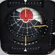
Head in the clouds Posted April 20, 2014 Posted April 20, 2014 Is there any software out there that would allow you to simulate such a thing?Maybe an aircraft design package exists to allow me to come up with some on-paper numbers? Following on from their CATIA CAD package, French Company Dassault Systemes produced Solidworks specifically for the Aerospace Industry although it was quickly adopted into other major branches of manufacturing. Solidworks incorporates very sophisticated computational fluid dynamics (CFD) and finite element analysis (FEA) capabilities. Commonly referred to as 'simulation and visualisation' they allow you to 'see' the effects of fluid flow and application of stress over and on the surfaces and members of a structure. The software can also generate a complete stress analysis for the individual members and the entire structure. There are other packages with similar capabilites, Autodesk's Inventor has add-ons for both. As for which to choose, a lot depends on which CAD platform(s) you are most familiar with. AutoCAD people will tell you that Inventor is the only way to go, realists with a handle on future trends are likely to start with, or learn, Solidworks. The essential difference is how the software goes about defining the model, AutoCAD is a geometric system and Solidworks is parametric although AutoCAD (and Inventor) now has a parametric design constraint tool. For the most part you don't need to know how the model is defined until you get into very complex solutions. Parametrics comes into its own when you want to change something you did near the beginning of the model and you want all associated members/items to change in a similar proportion, to remain 'linked' with the first item, for example. Most former NASA and Boeing engineers seem to favour Rhinoceros (Rhino), a NURBS-based geometric modelling package and it has FEA and a Grasshopper Components plug-in for CFD and files can be converted to Solidworks format to use those features if required. Many other engineering softwares will do the engineering calcs for you too - Tekla Structures (formerly X steel), Graitec Advance Steel etc, they are very expensive but you may know someone who has a seat. The main thing to keep in mind is that although (most) models from one format can be imported and exported from one package to another they lose their interactivity and so will not be 'live' within that other package, they will just be a simple solid or surface. In that case migrating from parametric to geometric is not so much of a problem because the solid can reasonably easily be rebuilt in AutoCAD for example, but if you take a geometrically developed solid into a parametric package it's just a reference solid and rebuilding it to make it 'live' (interactive with other parts of the model), means starting again. How much of a hurry are you in? For those who are competent in any 3D CAD package you can follow a tutorial and be able to do the basics in Solidworks in a couple of weeks but will only be slightly proficient in about three months and competent in twelve months. After a decade you'll still be learning - I'm talking full-time here ... Many people start their CAD work at school or college with AutoCAD and therefore the learning curve will be much quicker for them in Autodesk's Inventor but you still won't be able to do the clever stuff for a long while. The other consideration is cost. If you get yourself registered for something in the Engineering field at TAFE or Uni, for example, you can download limited functionality student versions of most of them, which stay activated for three years or so, and the extent of functionality is sufficient for most private purposes, quite enough to design an LSA for example. Once you go to the professional level you'll have spent enough on software to buy a brand new LSA ... The pro versions basic costs (excl add-ons and in USD) - Solidworks about $12K, Inventor $8-12K depending on the re-seller and it includes AutoCAD, Rhino/flamingo is the cheapest and best value for beginners at about $1K plus a few hundred for the add-ons, Tekla is about $35K and Advance is about $10-15K. If your only interest is to experiment a bit and see what difference a few changes make to the performance of a basic aircraft form you could have a play around with X-plane. It's quite a different concept, you download the (free) software and produce an aircraft model of your own design - or choose from thousands of online models - and change the basic model by dragging 'handles' until you have what you want. Then you define the engine power and type(s) and various other parameters and go and fly the plane in the simulator. Then go back into the model, change it and fly it again and compare the difference. The thing to remember with X-plane is that although the software makes a very nice rendered image of your plane for you to fly, the rendered image isn't fully representative of the plane you fly in the simulator because you are flying the parameters you input, not the model, so if you don't define the flaps accurately the performance won't reflect the flaps you may think you have, if you get me. Also, disregard a lot of what X-plane indicates about stall characteristics, it doesn't cope well with anything other than simple stall behaviour. Disclaimer - I've only played a little with X-plane so others know much more about it than I do, but some pretty experienced and successful designers speak well of it (for specific purposes) and use it as a matter of course to test their new design progress. Below are some images, the first three are examples of CAD FEA, the first showing the stress on a wheel as it would be when loaded with the weight of a car, stress on operating turbine wheels, a loaded chassis showing the point of greatest deflection. The rest are CAD CFD showing pressure distributions, the last one is probably something close to what you are looking for, and demonstrates why modern airliners have the bulge below the wing centre-section and have been able to reduce the size of the fillets as a result. Co-incidentally a very handy space for the gear and systems stowage as well - note how evenly spaced are the isobars.
djpacro Posted April 21, 2014 Posted April 21, 2014 When I get to a PC rather than iPad I will include a link to an extract from his book with that Me109 data ... http://www.wwiiaircraftperformance.org/me109/Hoerner-Me_109.pdf Is there any software out there that would allow you to simulate such a thing?... Maybe an aircraft design package exists to allow me to come up with some on-paper numbers?... Some around, I listed a number in a thread quite some time back. Here is one: http://www.aircraftdesign.com/ and another: http://www.darcorp.com/ 1
Head in the clouds Posted April 21, 2014 Posted April 21, 2014 http://www.wwiiaircraftperformance.org/me109/Hoerner-Me_109.pdfSome around, I listed a number in a thread quite some time back. Here is one: http://www.aircraftdesign.com/ and another: http://www.darcorp.com/ Good point djp, I'd forgotten about those. There's also the new and free parametric NASA one - Open VSP
Dafydd Llewellyn Posted April 21, 2014 Posted April 21, 2014 Is there any software out there that would allow you to simulate such a thing?I mean, I'm reasonably competent with maths and physics, but at this stage I'm..... well... like a dog in a forest not knowing which tree to pee on! You've given some good advice, but I don't know where to start to apply it all. Maybe an aircraft design package exists to allow me to come up with some on-paper numbers? Thanks, Gimballock. I expect there are quite a few out there - there are certainly airflow software packages that use finite element analysis, which produce pretty pictures (that may or may not be real); since I don't use them, I'm not familiar with them. A web search should find lots of them; people have been trying to get the "black magic" element out of aerodynamics for almost two centuries. Bill Whitney has a CD on the subject - and if you give me an email address, I can send you a few ramblings - and Stinton's book was written to do just what you are asking. Unless you are planning to go GA experimental, your design will have to fit into one of the existing categories, which usually have some defined limitations (weight, stall speed, etc). The starting point for any aircraft design is, what disposable load must it carry, how far, and how fast. Those factors dictate how big and heavy it must be. The aerodynamic form of it follows from that, not the other way around. The issues that dictate the layout are very often entirely different from what a lay person would normally expect, and if you start from the wrong end, you'll end up with a camel, not a horse. I'll give you an example - what dictated the shark-like shape of the Me 262 fuselage?
Bob Llewellyn Posted April 21, 2014 Posted April 21, 2014 Following on from their CATIA CAD package, French Company Dassault Systemes produced Solidworks specifically for the Aerospace Industry although it was quickly adopted into other major branches of manufacturing. Solidworks incorporates very sophisticated computational fluid dynamics (CFD) and finite element analysis (FEA) capabilities. Commonly referred to as 'simulation and visualisation' they allow you to 'see' the effects of fluid flow and application of stress over and on the surfaces and members of a structure. The software can also generate a complete stress analysis for the individual members and the entire structure.There are other packages with similar capabilites, Autodesk's Inventor has add-ons for both. As for which to choose, a lot depends on which CAD platform(s) you are most familiar with. AutoCAD people will tell you that Inventor is the only way to go, realists with a handle on future trends are likely to start with, or learn, Solidworks. The essential difference is how the software goes about defining the model, AutoCAD is a geometric system and Solidworks is parametric although AutoCAD (and Inventor) now has a parametric design constraint tool. For the most part you don't need to know how the model is defined until you get into very complex solutions. Parametrics comes into its own when you want to change something you did near the beginning of the model and you want all associated members/items to change in a similar proportion, to remain 'linked' with the first item, for example. Most former NASA and Boeing engineers seem to favour Rhinoceros (Rhino), a NURBS-based geometric modelling package and it has FEA and a Grasshopper Components plug-in for CFD and files can be converted to Solidworks format to use those features if required. Many other engineering softwares will do the engineering calcs for you too - Tekla Structures (formerly X steel), Graitec Advance Steel etc, they are very expensive but you may know someone who has a seat. The main thing to keep in mind is that although (most) models from one format can be imported and exported from one package to another they lose their interactivity and so will not be 'live' within that other package, they will just be a simple solid or surface. In that case migrating from parametric to geometric is not so much of a problem because the solid can reasonably easily be rebuilt in AutoCAD for example, but if you take a geometrically developed solid into a parametric package it's just a reference solid and rebuilding it to make it 'live' (interactive with other parts of the model), means starting again. How much of a hurry are you in? For those who are competent in any 3D CAD package you can follow a tutorial and be able to do the basics in Solidworks in a couple of weeks but will only be slightly proficient in about three months and competent in twelve months. After a decade you'll still be learning - I'm talking full-time here ... Many people start their CAD work at school or college with AutoCAD and therefore the learning curve will be much quicker for them in Autodesk's Inventor but you still won't be able to do the clever stuff for a long while. The other consideration is cost. If you get yourself registered for something in the Engineering field at TAFE or Uni, for example, you can download limited functionality student versions of most of them, which stay activated for three years or so, and the extent of functionality is sufficient for most private purposes, quite enough to design an LSA for example. Once you go to the professional level you'll have spent enough on software to buy a brand new LSA ... The pro versions basic costs (excl add-ons and in USD) - Solidworks about $12K, Inventor $8-12K depending on the re-seller and it includes AutoCAD, Rhino/flamingo is the cheapest and best value for beginners at about $1K plus a few hundred for the add-ons, Tekla is about $35K and Advance is about $10-15K. If your only interest is to experiment a bit and see what difference a few changes make to the performance of a basic aircraft form you could have a play around with X-plane. It's quite a different concept, you download the (free) software and produce an aircraft model of your own design - or choose from thousands of online models - and change the basic model by dragging 'handles' until you have what you want. Then you define the engine power and type(s) and various other parameters and go and fly the plane in the simulator. Then go back into the model, change it and fly it again and compare the difference. The thing to remember with X-plane is that although the software makes a very nice rendered image of your plane for you to fly, the rendered image isn't fully representative of the plane you fly in the simulator because you are flying the parameters you input, not the model, so if you don't define the flaps accurately the performance won't reflect the flaps you may think you have, if you get me. Also, disregard a lot of what X-plane indicates about stall characteristics, it doesn't cope well with anything other than simple stall behaviour. Disclaimer - I've only played a little with X-plane so others know much more about it than I do, but some pretty experienced and successful designers speak well of it (for specific purposes) and use it as a matter of course to test their new design progress. Below are some images, the first three are examples of CAD FEA, the first showing the stress on a wheel as it would be when loaded with the weight of a car, stress on operating turbine wheels, a loaded chassis showing the point of greatest deflection. The rest are CAD CFD showing pressure distributions, the last one is probably something close to what you are looking for, and demonstrates why modern airliners have the bulge below the wing centre-section and have been able to reduce the size of the fillets as a result. Co-incidentally a very handy space for the gear and systems stowage as well - note how evenly spaced are the isobars. [ATTACH]28023[/ATTACH] [ATTACH]28024[/ATTACH] [ATTACH]28025[/ATTACH] [ATTACH]28026[/ATTACH] [ATTACH]28027[/ATTACH] [ATTACH]28028[/ATTACH] [ATTACH]28031[/ATTACH] [ATTACH]28029[/ATTACH][ATTACH]28030[/ATTACH] The problem is the issue of forced convergence - FEM works well with essentially two-dimensional plates of limited number; and even in such cases, the algorithms have to have a predetermined "fudge factor" to garauntee that they converge (I've had some glorious non-convergences reported from Inventor...). As soom as the program takes over the meshing, the model becomes mathematically unstable; if forced in a pro-stability direction, it becomes inaccurate. Chaos theory shows that a large accumulation of small inaccuracies gives wildly variable results from the one dataset. FEM is a tool, that translates reality into 2-D triangular plates with imaginary thickness, and averages the properties as if the plates were rectangular. It gives very precise answers, but the accuracy is suspect in all but fairly simple structural models with intelligent - not automated - control of the meshing. Computer programmers neither understand this, nor care. It is my understanding that the Joint Strike Fighter FEM teams entered an intractible dispute, and they had to build two extra prototypes to resolve the FEM disgreements (back about 2006/7). Hoerner himself states that there is no credible method for predicting laminar to turbulent transition around a 3-D shape, and the physics haven't changed...
Recommended Posts
Create an account or sign in to comment
You need to be a member in order to leave a comment
Create an account
Sign up for a new account in our community. It's easy!
Register a new accountSign in
Already have an account? Sign in here.
Sign In Now